THE SHOWER LAB VIEW 07 User manual

Illustration - View 07
H1 Handle
Right Hand
Open Out
VIEW 07
07/2019 V 2.2

IMPORTANT
•This shower screen / enclosure must be installed by suitably qualified individuals. We
recommend a minimum of two people for safe assembly of certain sections of this screen.
•Ensure all appropriate safety equipment, especially protective footwear, safety glasses
and gloves are used.
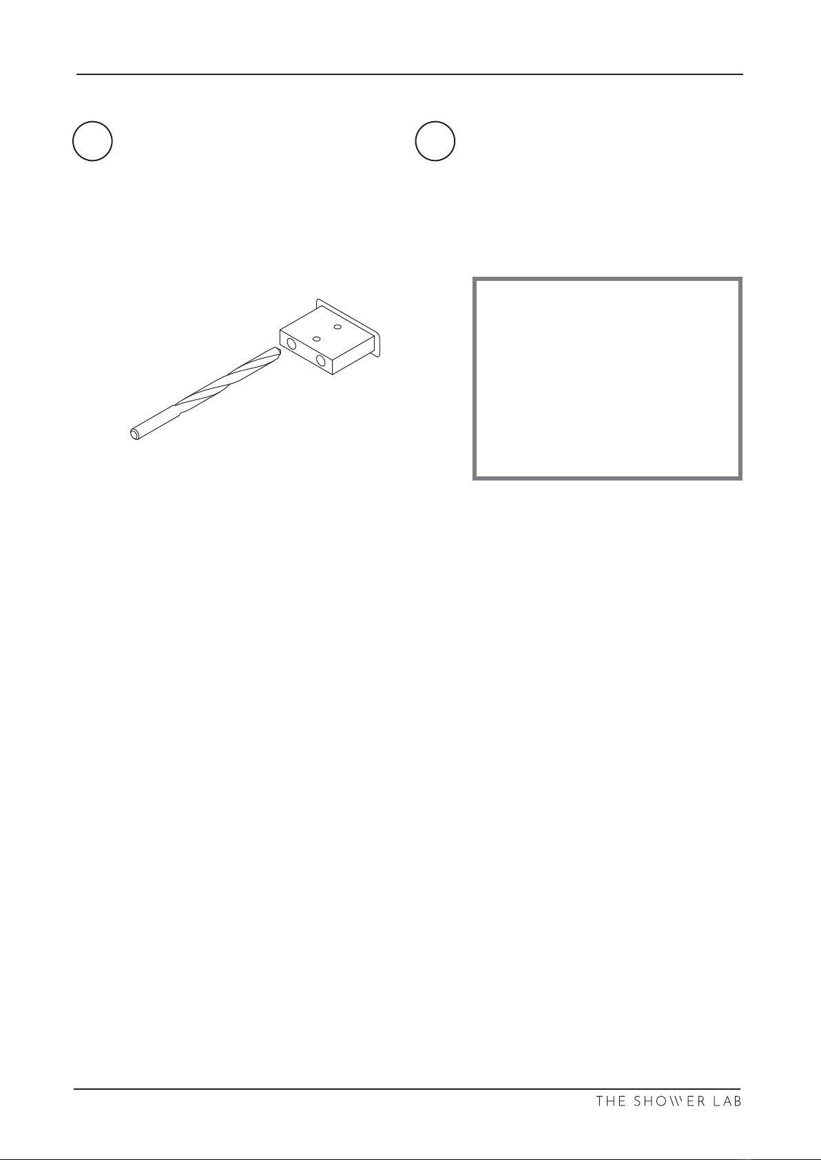
•When drilling holes in ceramic tiles, use masking tape to prevent the drill from slipping:
DO NOT use hammer action as this will crack the tiles. Use a high quality drill bit to ensure
a clean, precise hole.
Tighten hinges and brackets to the recommended 15.6N.
•
•
Please leave these instructions with the customer following installation.
PRIOR TO INSTALLATION
•Before disposing of the packaging and prior to commencing assembly, please check all
the components to ensure that they have been supplied correctly and are undamaged.
Subsequent claims for missing or damaged pieces will not be accepted once the
packaging has been disposed of and installation commenced.
•In the event of any queries please contact your supplier quoting the relevant model
information.
•The Tray / Tiled floor on which this screen is to be installed must be level on all sides.
•It may be necessary to use alternate fixings to those supplied, depending on the properties
of the walls to be fixed to.
•Use the protective corners supplied at all times until the glass is moved to its final position.
•Ensure that the glass is installed correctly, taking care to avoid installing the glass upside
down. On certain panels an easy clean coating is applied to one side only, this is clearly
marked with a sticker on the non-coated side. The coated surface is to be fitted inwards
towards the inside (wet side) of the screen.
•Ensure that all surfaces to be sealed are clean and dry prior to applying the silicone
sealant. Use a high grade fungal resistant sealant.
•Allow a minimum of 48 hours after application of the silicone sealant prior to using the
screen.
TOOLS & MATERIALS REQUIRED
Junior Hacksaw
Straight Edge (Steel
Rule)
Fine Tooth File
Set or Roofing
Square
Masking Tape
Modelling Knife
Spirit Level
Pencil
Silicone Gun
Power Drill
Ø6mm Masonry Drill Bit
2x Suction Glass Lifters
High Quality Silicone Sealant
Tape Measure
Pozi-drive
Screwdrivers, PZ1&2
Safety Glasses and
Gloves
CARE AND MAINTENANCE
(please ensure that these instructions are left with the installed unit)
•We recommend routine cleaning of your screen / enclosure with hot water using a soft
cloth, then drying with a dry soft cloth or chamois leather.
Ritec Aftercare for Shower Glass is recomended for best results.
•All glass has been treated with EASY CLEAN glass finish and care must be taken to avoid
any abrasive cleaning products that may damage the special surface protection.
•DO NOT use acidic based de-scaler products or products containing bleaches or solvents.
Digital Torque Wrench
VIEW 07
07/2019 V 2.2

Return panel
x1
Supplied Parts
Inline Panel
x1
Door
x1
90° Corner insert
x1
Glass support
x2
Square Alignment Jig
x1
Each bracket includes
2x Screws and Wall Plugs
90° Glass to wall bracket
x2
Glass to wall hinge
x2
(Each hinge includes
3x Screws and wall plugs)
90° Glass to glass bracket
x2
Door Handle
(Option dependant)
x1
VIEW 07
07/2019 V 2.2

Supplied Parts
Glass to glass bubble “h” seal
x1
Underframe
x2
Underframe top
x1
Wall channel
x1
Bottom door seal
x1
3mm Spacer1mm Spacer
Glass to wall seal
x2
VIEW 07
07/2019 V 2.2

Please use this page to nd which stay bar your enclosure has been supplied with.
SB1 - With Glass clamp
SB7 - With Glass clamp
and T connector
VIEW 07
07/2019 V 2.2

These instructions are for a corner enclosure (Door hinged o wall). This view shows a right
handed set up with SB7 stay bar connecting the return and inline panel together, xed to the
wall.
Please use the below diagram to reference the list of parts.
I
HUnderframe Bottom
Underframe Top
L
K
JWall Channel
Glass to Glass Bubble “h” Seal
Glass to Wall Seal
MBottom Door Seal
NStay Bar (SB7 shown)
A
B
C
D
F
E
G
Return Panel
Inline Panel
Door (H1 Handle option shown)
Glass to Wall Bracket
90° Glass to Glass Bracket
Handle (Option Dependant)
Glass to Wall Hinge
A
E
EF
F
D
D
J
M
H
I
L
G
H
B
NC
K
VIEW 07
07/2019 V 2.2
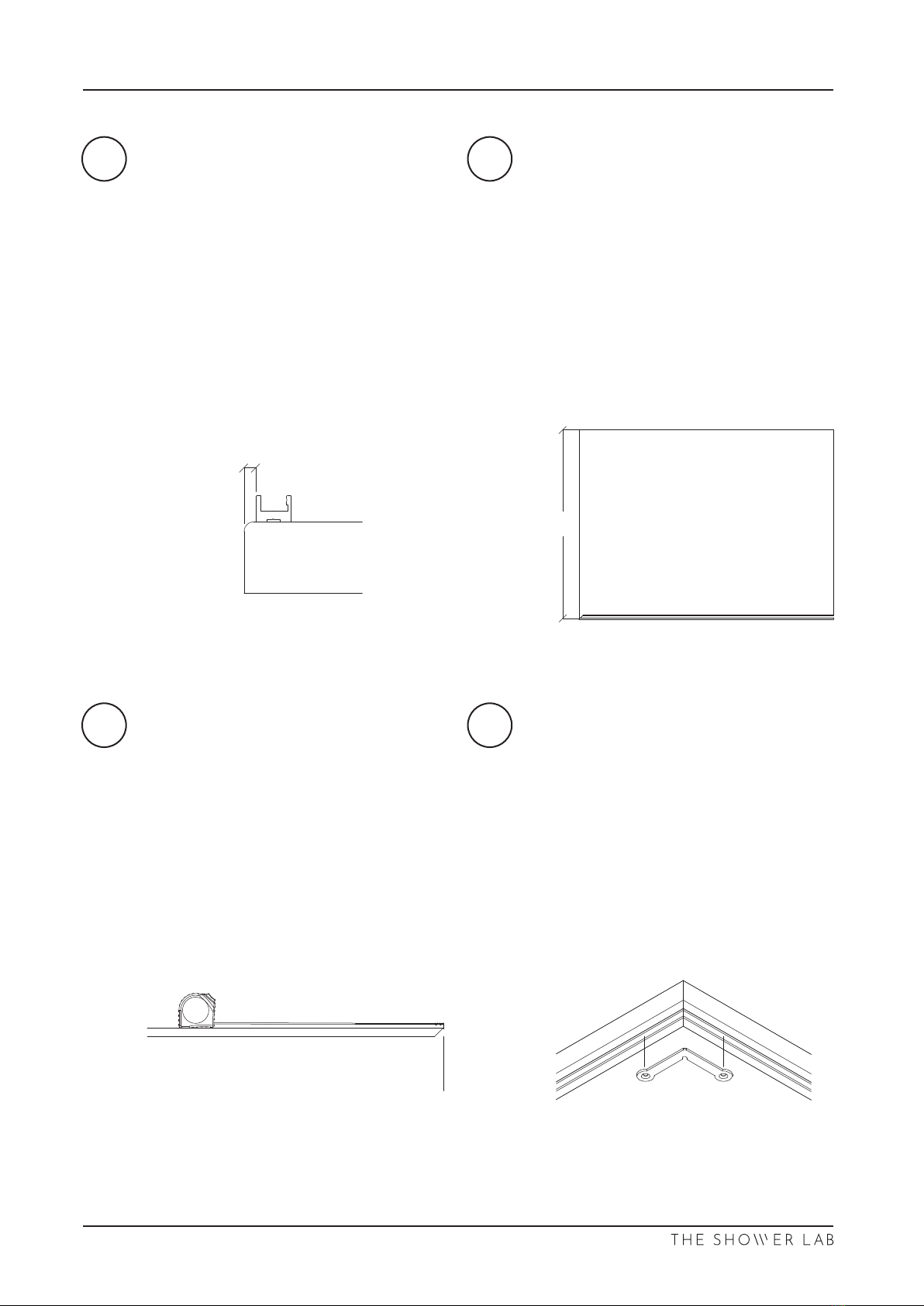
2
01/20
3-8mm
Outside of shower Inside of shower
(Wet Side)
Shower Tray
X
Mitred End
VIEW 07
07/2019 V 2.2

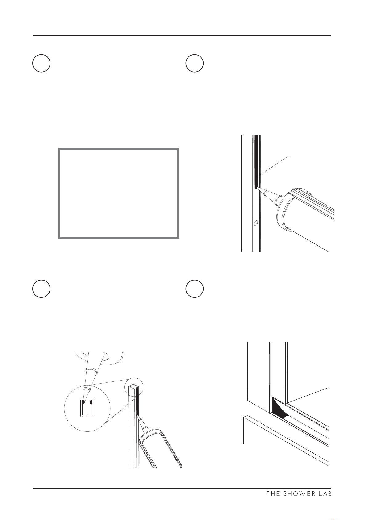
Insert the square alignment jig to
locate the wall channel. Using a spirit
level, ensure the wall channel is
Mark the pre-drilled holes.
squarely insert the return panel into
the wall channel and lower onto the
spacers. Take great care NOT to knock
the corners as this can cause the panel
56
7 8
Remove the channel.
Using a 6mm high quality drill bit for a
clean and precise hole, drill the marked
the channel.
WARNING
The glass is heavy and may
damage the oor or underframe if
handled incorrectly. It is advisable
to use a suitable non-slip
protective mat or piece of carpet.
Never rest the glass across the
underframe as this may cause
damage.
Professional Tip
If drilling ceramic tiles, place
masking tape on the tiles before
marking and drill through the
tape to prevent the drill bit from
skidding.
DO NOT use Hammer Action as
this will break the tiles.
Place spacers into the underframe
evenly, as shown below. Begin with the
4mm spacers.
NOTE: There must always be a
minimum set of 1mm spacers used
under the glass panel.
02/20
4mm
4mm
VIEW 07
07/2019 V 2.2

Using a spirit level, align the return
9
03/20
No Gap
4mm
4mm
VIEW 07
07/2019 V 2.2
13 14
15 16
Place the door supports evenly over
the frame.
With one person inside the enclosure,
supports as indicated.
the inline panel.
04/20
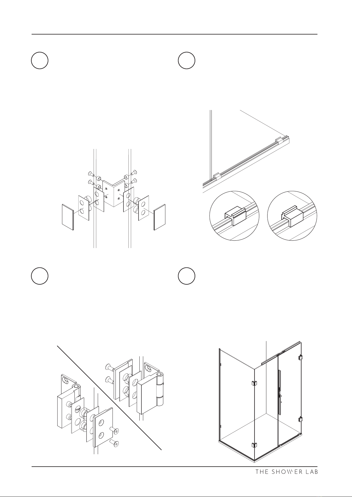
should be located inside the enclosure.
OUTWARD Opening
INWARD Opening
Outside enclosure
Outside enclosure
Inward opening Outward opening
VIEW 07
07/2019 V 2.2
17 18
19 20
05/20
First, check there is a gap of 9mm
a 6mm gap between the door and the
inline panel. If this is not achievable, a
bespoke door may be necessary.
9
Hole “B”
See step 20
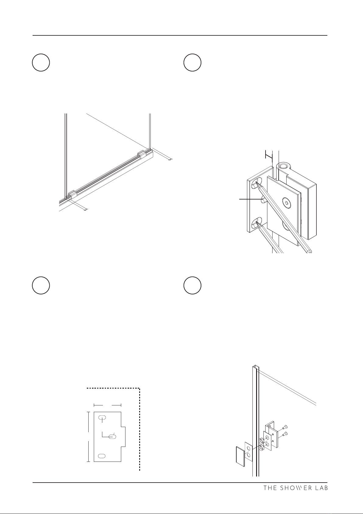
Secondly, mark the accessible holes
the wall.
If you have an INWARD opening door,
mark all 3 holes.
It is recommended to use masking tape
side.
If OUTWARD opening, use the template
on the last page to locate Hole “B”.
Use masking tape on the wall to mark
the measurements.
Tear Here
Tear Here
40mm
70mm
27mm
15mm
Hole “B”
See nal page for full scale template
Loosely assemble the 90° glass to wall
brackets onto the return panel. The
located inside the enclosure. Ensure
the hole centres align.
6mm Gap
(Handle Side)
9mm Gap
(Wall Side)
VIEW 07
07/2019 V 2.2
21 22
23 24
06/20
Using a pencil, mark the holes where
the 90°glass to wall bracket will be
Using masking tape onto the wall to
4mm
4mm
4mm
4mm
VIEW 07
07/2019 V 2.2
25 26
27 28
07/20
Using a 6mm high quality drill bit for a
clean and precise hole, drill the marked
areas and fully insert the wall plugs.
Professional Tip
If drilling ceramic tiles, place
masking tape on the tiles before
marking and drill through the
tape to prevent the drill bit from
skidding.
DO NOT use Hammer Action as
this will break the tiles.
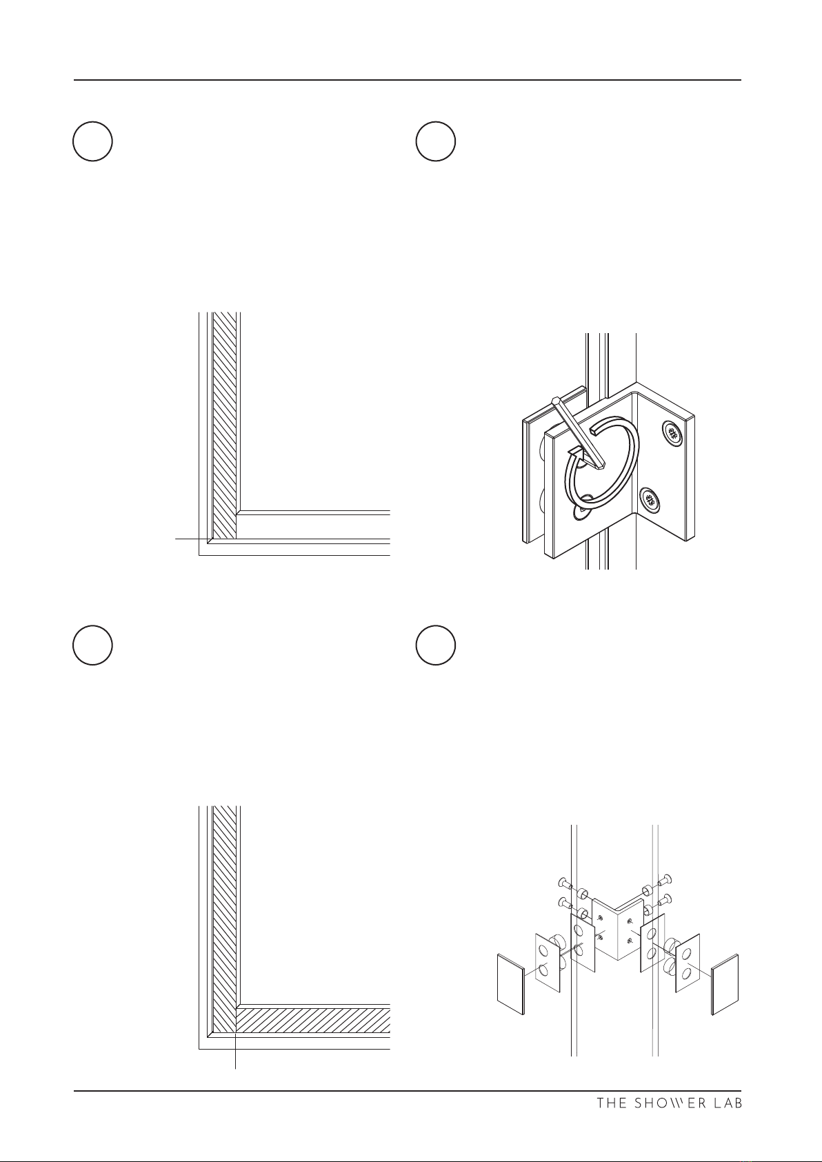
sealant as indicated. Run a bead of
silicone sealant down the back face to
Silicone
Run beads of silicone sealant down the
inside walls of the channel as shown.
channel with silicone.
It is very important to put a good
amount of silicone in the corner where
the wall channels meet the
underframe. This area needs to be
properly sealed to prevent any water
leakage.
VIEW 07
07/2019 V 2.2
29 30
31 32
Check the spacers are in their noted
posi�ons.
Carefully lower the inline panel back
into the channel and onto the spacers.
Ensure the panel is pushed �ght against
the return panel.
Check the spacers are in their noted
posi�ons.
Carefully lower the return panel back
into the channels and onto the spacers.
Ensure there is no gap at the front of
the under-frame.
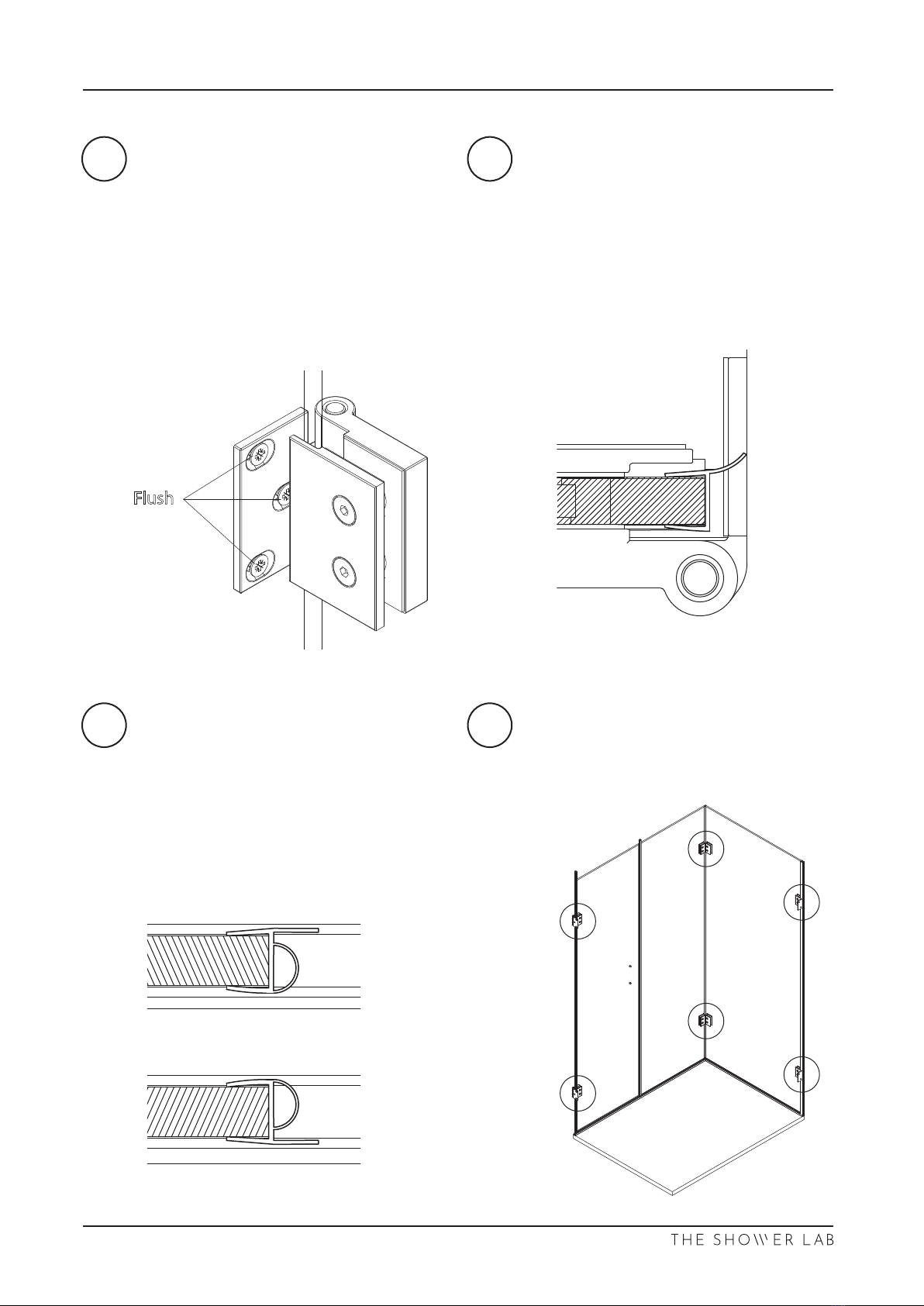
Screw the brackets to the walls.
Evenly �ghten the screws un�l the
gaskets just “nipping” the glass.
Tighten all glass screws to 15.6N.
DO NOT fit the cover plates.
08/20
Assemble the 90° glass to glass
brackets back onto the panels. Evenly
�ghten the screws un�l the gaskets are
“nipped”.
Tighten all screws to 15.6N.
DO NOT fit the cover plates yet.
No Gap
No Gap
VIEW 07
07/2019 V 2.2
33 34
35 36
09/20
Flush
Inside Enclosure
Open Out
Inside Enclosure
Open In
VIEW 07
07/2019 V 2.2

37
10/20
Check which stay bar configura�on
your screen has been supplied with and
refer to the relevant instruc�ons below.
(You can find this out at the front of
these instruc�ons).
Cong A - SB1 Page 09
Cong B - SB7 Page 12
VIEW 07
07/2019 V 2.2

Mark the final dimension on the stay
bar tube, wrapped with some masking
tape. Carefully use a fine toothed
junior hacksaw and fine file to cut and
finish the edge.
DO NOT discard the off cut.
A1 A2
Stay Bar Conguration A - SB1
Measure the distance from the inside
face (wet side) of the return panel to
the wall opposite. Ensure this
measurement is truly horizontal.
Subtract 6.5mm to get your final
dimension.
11/20
X
Inside of Glass
VIEW 07
07/2019 V 2.2
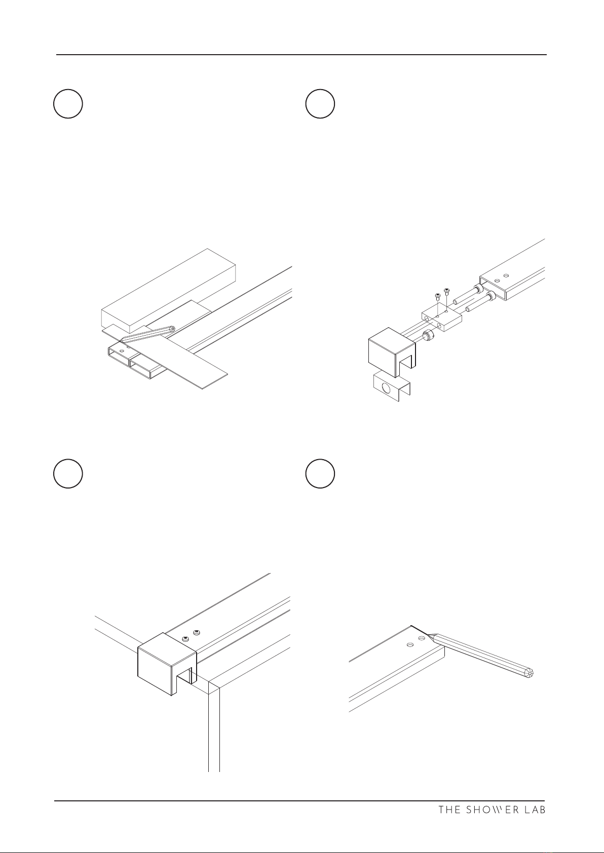
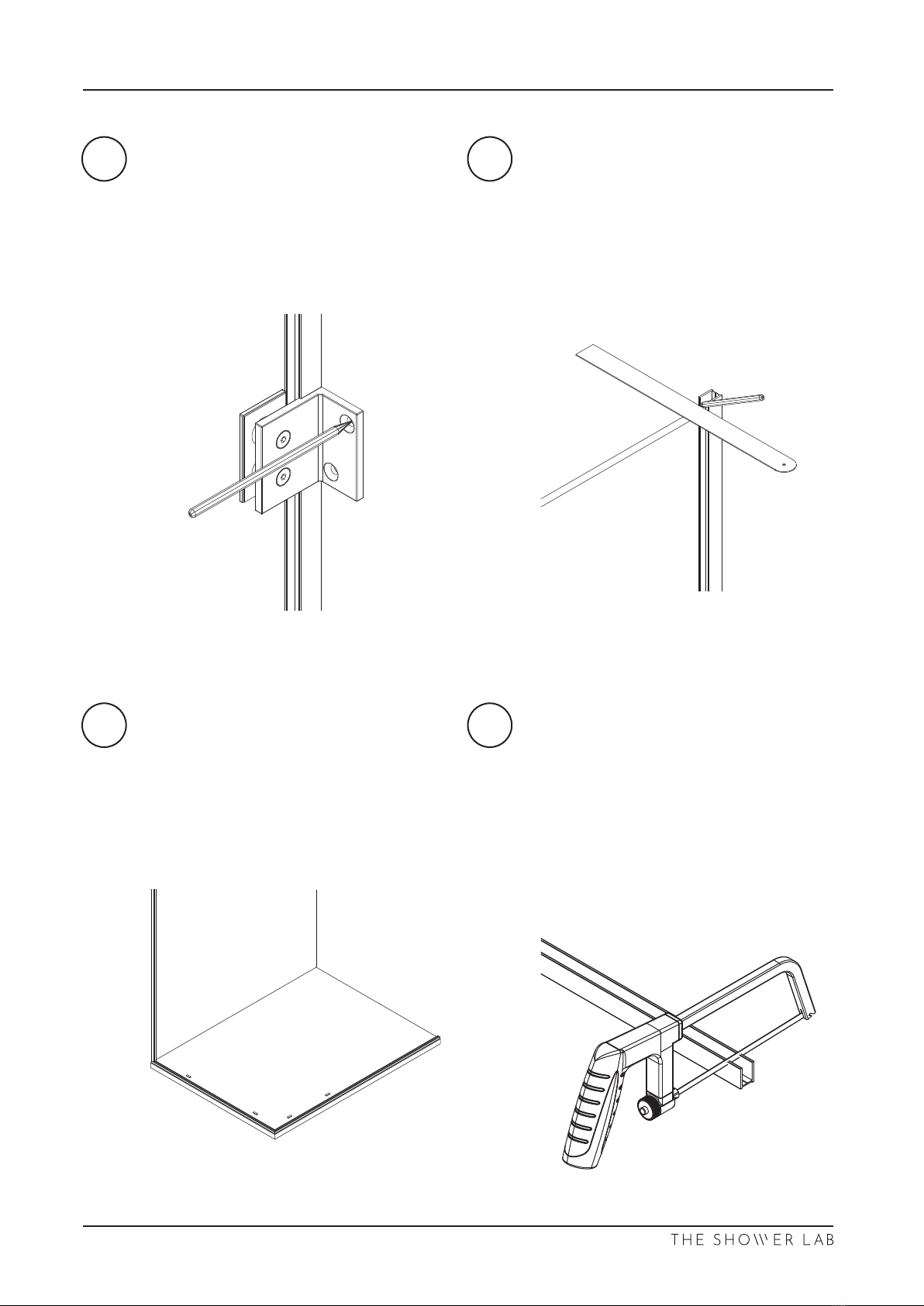
Align the off cut to the new end.
Use a set square to locate the new
holes.
With a 4mm drill bit, carefully drill
through one side of the stay bar tube.
Ensure the stay bar is square and level.
Mark the end loca�on on the wall.
Remove the stay bar.
A3 A4
A5 A6
Stay Bar Conguration A - SB1
Assemble the glass clamp to the stay
bar as shown.
Secure the glass clamp over the return
panel making sure the glass is fully
inserted into the groove about 15mm
from the end of the glass.
12/20 07/2019 V 2.2
A7 A8
Stay Bar Conguration A - SB1
13/20
Using a 5mm high quality drill bit for a
clean and precise hole, drill the marked
areas, fully insert the wall plugs and fix
the connectors to the wall.
Professional Tip
If drilling ceramic tiles, place
masking tape on the tiles before
marking and drill through the
tape to prevent the drill bit from
skidding.
DO NOT use Hammer Action as
this will break the tiles.
Posi�on the stay bar connectors central
to the markings. With a small drill bit
mark the holes for drilling.
Use masking tape on the �les to mark.
07/2019 V 2.2

Secure the stay bar to the return panel,
ensuring the glass is fully inserted into
the clamp.
B1 B2
Stay Bar Conguration B - SB7
Follow steps A1-A4.
Secure the T Connector to the inline
panel as shown.
14/20
VIEW 07
07/2019 V 2.2
Other manuals for VIEW 07
1
Table of contents
Other THE SHOWER LAB Shower Cabin manuals


