Theben Training Case KNX User manual

2022-05-16_309711 01
Manual for Training Case
KNX & KNX Programming
with ETS

Manual for the training case KNX
Contents
1Further information on Theben KNX is available at: 3
2Case views 4
2.1 Case lid showing rooms / functions 5
2.2 Case base with view of devices 5
3Safety information and instructions on preparing the case safely 6
3.1 Setting up the case 6
3.2 Key to symbols 7
3.3 Technical Data 7
3.4 Proper use 8
3.5 Cleaning device 8
4The KNX bus system 9
4.1 How did KNX originate? 9
4.2 What is a KNX system? 9
4.3 KNX devices 10
4.4 What can KNX be used for? 11
4.5 ETS software 11
4.6 KNX Secure 13
5KNX devices used in the case 15
5.1 System devices 15
5.2 Terminal devices 16
6Start-up 28
6.1 KNX IP connection 28
6.2 XLR connection 28
6.3 Actual start-up 29
7Resetting devices to factory settings 30
7.1 BUS reset 30
7.2 Resetting devices 30
8Extending the case with further devices 33
9Support 34
10 Contact 35

Further information on Theben KNX is available at:
Manual for the training case KNX 3
1Further information on Theben KNX is
available at:
Further information on Theben KNX is available at:
https://www.theben.de/
The functions of the operating controls of individual devices are described in the
operating instructions provided at https://www.theben.de/

Case views
Manual for the training case KNX 4
2Case views
Case views
Manual for the training case KNX 5
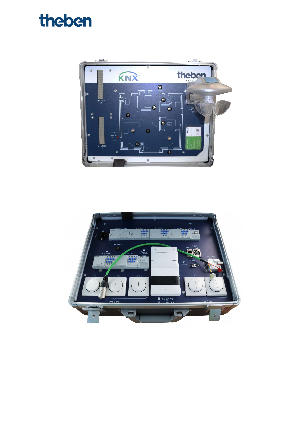
2.1 Case lid showing rooms / functions
2.2 Case base with view of devices

Safety information and instructions on preparing the case safely
Manual for the training case KNX 6
3Safety information and instructions on preparing
the case safely
3.1 Setting up the case
Please make sure that the case is placed fully on a stable work surface.
This helps to avoid any injuries which could occur if the training case were
to fall from the work surface as well as any associated damage to the
training material.
Also make sure there is enough space to use a laptop and mouse.
You can then open the lid. The lid of the training case has been purposely
designed with two hinges that lock into place so that the lid cannot fall
down if someone inadvertently touches or knocks the case as they walk
past, thereby preventing people from being injured when they are working
with the case.
Plug the power cable firmly and securely into the IEC socket inside the
case. The case is equipped with an internal fuse (1.25 A T) right next to
the IEC socket, which can also be replaced by the customer (not by the
learners).
Only the supplied power cord may be used.
The mains plug may only be plugged into an earthed socket.
The earthed plug or the IEC plug of the mains cable must always remain
accessible, so the mains cable can be disconnected in an emergency.
The device is suitable for use in schools for supervised pupils aged 11
years or older.
Safety information and instructions on preparing the case safely
Manual for the training case KNX 7
To avoid personal injury, an operating voltage must not be applied to the
case if it is damaged. In the event of damage, the case must be inspected
by qualified personnel and repaired before it is used again.
3.2 Key to symbols
Intended for use in schools by learners aged 11
years or older under the supervision of the
operator.
Caution: Observe operating instructions!
Installations/system extensions must not be
carried out by LEARNING USERS!
3.3 Technical Data
Operating voltage: 230 V AC, 50 Hz, +10/-15 %
Input power: 140 mA/23 W
Ambient temperature: 5 °C ... 45 °C
Protection rating: IP 40
Pollution degree: 2
Protection class: I (if the device is used in a manner not specified by
the manufacturer, the protection provided by the
device may be impaired)
Theben AG herewith declares that this type of radio installation complies with
Directive 2014/53/EU. The complete text of the EU Declaration of Conformity is
available at the following Internet address:
www.theben.de/red-konformitaet

Safety information and instructions on preparing the case safely
Manual for the training case KNX 8
3.4 Proper use
The case
−may only be used inside buildings.
−may only be used at altitudes up to 2000 m.
−may only be used in environments with a relative humidity up to 80 %
RH (non-condensing).
3.5 Cleaning device
Only clean the training case with a damp cloth when it is open.

The KNX bus system
Manual for the training case KNX 9
4The KNX bus system
Intelligent bus systems are used to improve the quality of buildings in terms of
operating costs, safety and flexibility.
4.1 How did KNX originate?
was a system developed and marketed by the EIB Association (EIBA). In 1999,
the EIBA, the Batibus Club International (BCI, France) and the European Home
Systems Association (EHSA, Netherlands) joined forces. In this fusion, the new
name KNX was created and the KNX Association was founded with its
headquarters in Brussels.
4.2 What is a KNX system?
A KNX system is a bus system for building control. This means that all devices
use the same transmission method and can exchange data via a common bus
line. This means:
Access to the bus line must be clearly controlled (bus access procedure).
A large share of the transmitted data is not user data (e.g. light on/light
off), but address information (from where does the data come, where is
it directed to?).
Another important feature of the KNX bus system is its decentralised structure.
A central control device is not necessary. The "intelligence" of the system is
distributed across all participants. However, central devices are not excluded. If
required, e.g. for very special applications, central devices might be used as an
option. Each device, or each bus sharing unit, has its own microprocessor. One
major advantage of decentralisation is that if one device fails, the remaining
devices continue to function. Only the applications relating to the failed device
are disturbed.
Apart from system devices (power supply, programming interface, etc.), a
general distinction is made in the KNX system between sensors and actuators.
Sensors are devices which detect events in the building (button actuation,
motion, exceeding/falling below a temperature value, etc.), convert these into
telegrams and then transmit them (data packets). Devices receiving telegrams
and converting the commands they contain into actions are called actuators.
Sensors represent the command transmitters, actuators the command receivers.
The KNX bus system
Manual for the training case KNX 10
4.3 KNX devices
KNX systems distinguish between system devices and terminal devices. System
devices are, for example, power supplies, couplers and programming interfaces.
Terminal devices are, for example, sensors and actuators.
4.3.1 Terminal devices: sensors, actuator sans bus coupling units
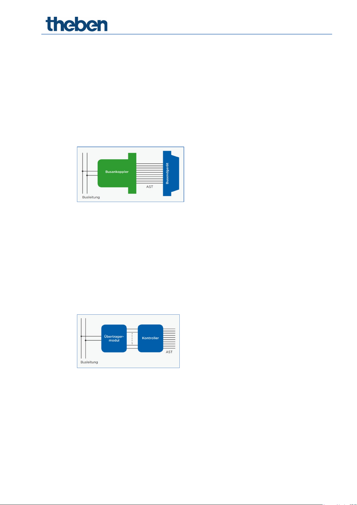
Bus sharing unit
All standard bus sharing units consist of two parts: bus coupling unit and bus
terminal device.
Structure of a bus sharing unit
If separable, the two devices are connected via the standardised ten- or twelve-
pin user interface (AST). Instead of the abbreviation AST, the abbreviation PEI
(Physical External Interface) is often used. For bus coupling unit, the first letters
of the term (BCU) are often used as an abbreviation.
Bus coupling unit
For bus coupling units permanently installed in devices, manufacturers can use
a ready-made bus interface module (BIM) or a KNX chipset. The basic structure
of the bus coupling unit is always the same. It consists of the two function
modules: bus coupling unit controller and transformer module.
Structure of a bus coupling unit
The transformer module determines the medium for which the bus coupling unit
is used. Common variants are bus coupling units with transformer module for
KNX TP (twisted pair) and for KNX PL (power line).

The KNX bus system
Manual for the training case KNX 11
4.3.2 System devices
KNX system devices are devices that predominantly perform special tasks, e.g.
Structuring of KNX topology
Power supply
Programming
4.4 What can KNX be used for?
The KNX bus controls the lighting and blinds or shading devices, the heating, as
well as the locking and alarm system of the building. KNX can also be used for
remote monitoring and control of a building. Control is performed by the user or
by a computer, which is equipped with the appropriate software. Originally
focussed on commercial buildings, KNX is increasingly being used in residential
buildings and especially single-family homes.
A control device, called "actuator", is installed between the consumer (e.g.
electrical appliance, lamp, window opener, etc.) and the Mains voltage. The
actuator is connected to the KNX bus and receives data from it in the form of
Telegrams. These telegrams come either directly from a sensor (e.g. switch,
brightness, temperature or CO2 sensor) or indirectly from a computer, which
controls time-controlled circuits and other evaluations of sensor data,
depending on the programming, and controls actuators accordingly.
If an actuator receives the command to supply voltage to the consumer, it
switches the mains voltage through to the device.
4.5 ETS software
A single manufacturer-independent engineering tool software ETS® allows
planning, configuration and commissioning of all KNX-certified products. The
tool allows the system integrator to combine different applications with
products from different manufacturers in one installation.
4.5.1 Tasks of the ETS
Usually, a KNX system is configured in S-mode, i.e. by using a computer and the
ETS installed on it. Here, the ETS is used to edit the application programmes
provided by the manufacturers for their products. Among other things, the
following can be done:
Downloading the manufacturer's application programmes from the
Internet (online catalogue) or from the database provided by the
manufacturer (e.g. via their website).
Setting the parameters of the application programmes.
Connecting the appropriate communication objects of the individual
application programmes by means of group addresses.
The KNX bus system
Manual for the training case KNX 12
Downloading the application programmes from the ETS to the KNX
devices.
In addition to the configuration and commissioning tools, the ETS also contains
extensive programme components for diagnosis and troubleshooting.
4.5.2 Structure of the ETS
The ETS is a software created according to Windows design rules. The ETS has
different work windows (main work window, group address window, topology
window) displaying the KNX installation to be edited in different ways.
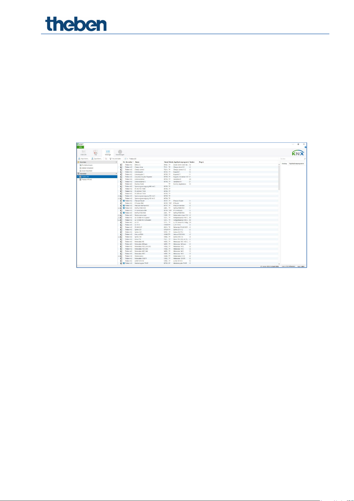
4.5.3 Configuration
After installing the ETS on the computer, a system cannot yet be configured.
First of all, the manufacturer's product data have to be loaded into the ETS. The
manufacturers of KNX products provide these data free of charge. They are
available either directly from the manufacturer or on the internet. Alternatively,
the ETS online catalogue can be used. After importing these data into the ETS,
the actual configuration can begin.

The KNX bus system
Manual for the training case KNX 13
4.6 KNX Secure
ETS 5 Version 5.5 and higher support secure communication in KNX systems. A
distinction is made between secure communication via the IP medium using
KNX IP Secure and secure communication via the TP and RF media using
KNX Data Secure.
In the ETS catalogue, KNX products supporting "KNX Secure" are clearly
identified :
As soon as a "KNX-Secure" device is included in the project, the ETS requests a
project password. If no password is entered, the device is included with Secure
Mode deactivated. However, the password can also be entered or changed later
in the project overview.
4.6.1 Start-up with KNX Data-Secure
For secure communication, the FDSK (Factory Default Setup Key) is required. If a
KNX product supporting "KNX Data Secure" is included in a line, the ETS
requires the input of the FDSK. This device-specific key is printed on the device
label and can either be entered by keyboard or read by using a code scanner or
notebook camera.
Example of FDSK on device label
After entering the FDSK, the ETS generates a device-specific tool key. The ETS
sends the tool key to the device to be configured via the bus. The transmission
is encrypted and authenticated with the original and previously entered FDSK
key.
Neither the tool key nor the FDSK key are sent in plain text via the bus.
After the previous action, the device only accepts the tool key for further
communication with the ETS.
The FDSK key is no longer used for further communication, unless the device is
reset to the factory setting: In this case, all set safety-related data will be
deleted.
The ETS generates as many runtime keys as needed for the group
communication you want to protect. The ETS sends the runtime keys to the
device to be configured via the bus. Transmission takes place by encrypting and
authenticating them via the tool key. The runtime keys are never sent in plain
text via the bus.

The KNX bus system
Manual for the training case KNX 14
The FDSK is saved in the project and can be viewed in the project overview. All
keys for this project can also be exported (backup).
During configuration, it can be defined subsequently which functions/objects
are to communicate securely. All objects with encrypted communication are
identified by the "Secure" icon in the ETS :
Keep the FDSK key safe, because if it is lost, it is impossible or difficult to
reproduce.
4.6.2 Start-up without KNX Data-Secure
Alternatively, the device can also be put into operation without KNX Data
Secure. In this case, the device is unsecured and behaves like any other KNX
device without KNX Data Secure function.
To start up the device without KNX Data Secure, select the device in the
'Topology' or 'Devices' section and set the 'Secure start up' option in the
'Properties' area of the 'Settings' tab to 'Disabled'.

KNX devices used in the case
Manual for the training case KNX 15
5KNX devices used in the case
The devices installed in the case are divided into system devices and terminal
devices.
5.1 System devices
5.1.1 KNX power supply PS 160 mA
https://www.theben.de/de/ps-160-ma-t-knx-9070956
Power supply 160 mA with auxiliary voltage of 30 V DC
Supply and monitoring of KNX system voltage
This voltage supplies the bus coupling units via which each KNX device
communicates with the other networked KNX devices
5.1.2 KNX USB interface
https://www.theben.de/de/schnittstelle-usb-knx-9070397
For communication between PC and KNX system to be programmed
Support of KNX Data Secure communication

KNX devices used in the case
Manual for the training case KNX 16
5.1.3 KNX IPsecure Router
https://www.theben.de/de/ipsecure-router-knx-9070770
Router/interface/line coupler IP and KNX
For data exchange between KNX and IP networks
Support of KNX IP Secure
The KNX IPsecure Router allows telegrams to be forwarded between
different lines via a LAN (IP) as a fast backbone (main line). The device
can also serve as a programming interface to connect a PC to the KNX
bus (e.g. for ETS programming)
5.2 Terminal devices
5.2.1 RM 8 S KNX
https://www.theben.de/de/rm-8-s-knx-4940220
The 8-way switch actuator from the FIX1 series switches electrical loads
(lamps)
Manual operation on the device (even without bus voltage)
Links, type of contact (opening contact/NO contact) and participation in
central commands such as permanent on, permanent off, central
switching and save/load scene

KNX devices used in the case
Manual for the training case KNX 17
Adjustable switch functions: e.g. on/off, pulse, on/off delay
Staircase light with pre-warning
5.2.2 BM 6 T KNX
https://www.theben.de/de/bm-6-t-knx-4940230
The 6-way binary input of the FIX1 series is used to connect 10 V–
240 V AC/DC contacts or similar
2 additional channels operable by buttons on the device, but without
input
Manual operation on the device (even without bus voltage)
All inputs can be operated with different voltages and at different
potentials
Free allocation of functions: switch/push button, dimming, blinds/roller
blinds, counter, repeat telegram, sequences
KNX devices used in the case
Manual for the training case KNX 18
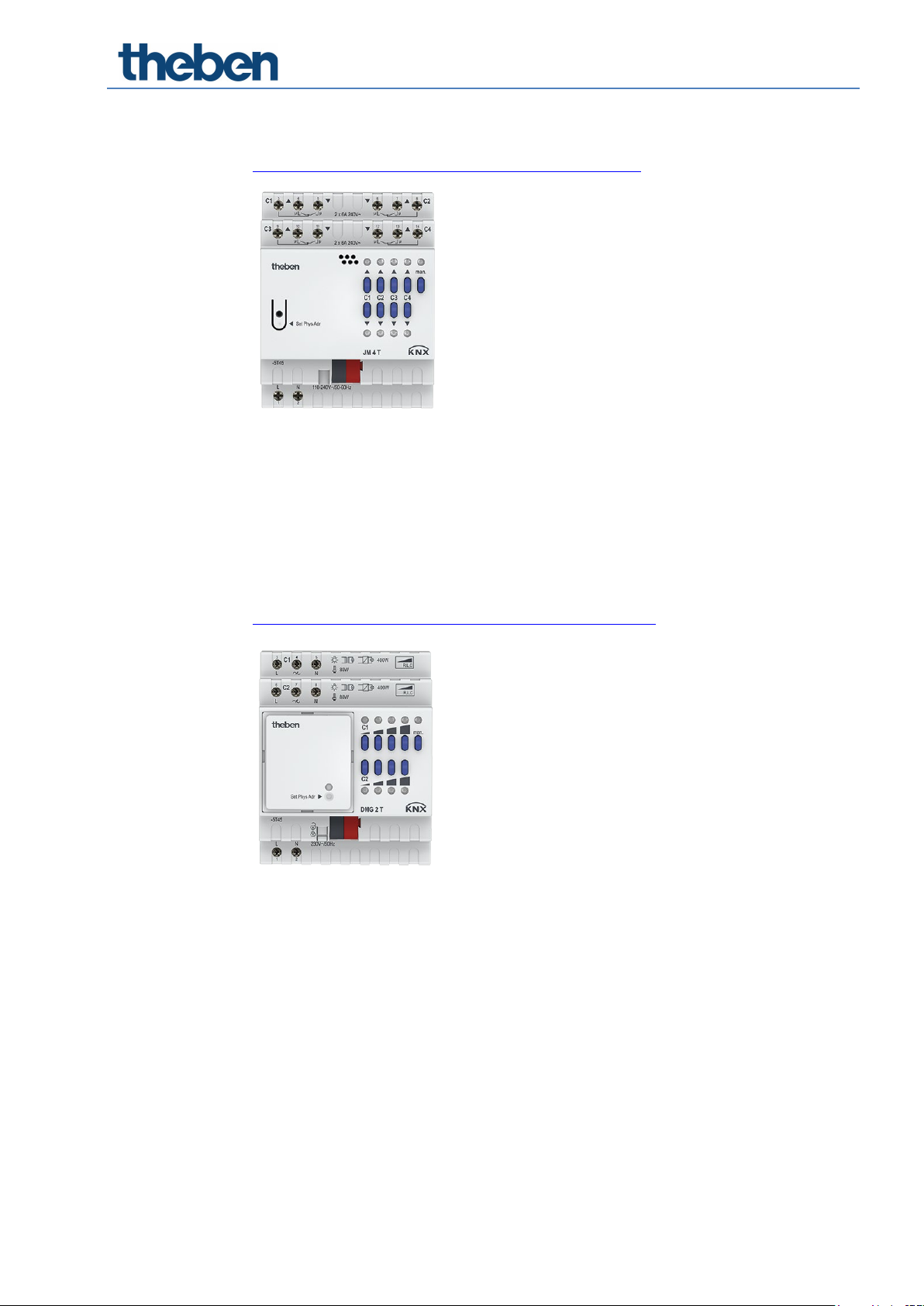
5.2.3 JM 4 T KNX
https://www.theben.de/de/jm-4-t-knx-4940250
The 4-way blinds actuator of the FIX1 series switches electrically-driven
blinds, roller blinds, awnings or similar hangings as well as ventilation
flaps for mains voltage
Manual operation on the device (even without bus voltage)
With LED Up and Down switching status display for each channel
5.2.4 DMG 2 T KNX
https://www.theben.de/de/dmg-2-t-knx-4930270
The 2-way universal dimmer actuator of the MIX2 series switches and
dims the brightness of incandescent lamps, high-voltage and low-
voltage halogen lamps, dimmable compact fluorescent lamps (energy-
saving lamps) or dimmable LED lamps for 230 V
For extension to up to 6 channels
Dimming range 0-100%
Also suitable for controlling fans
Up to 2 MIX or MIX2 extension modules can be connected to a base
module
Device and KNX bus module can be exchanged independently of each
other
KNX devices used in the case
Manual for the training case KNX 19
Manual start-up and operation of the switch actuators is also possible
without the removable KNX bus module
Manual operation on the device (even without bus voltage)
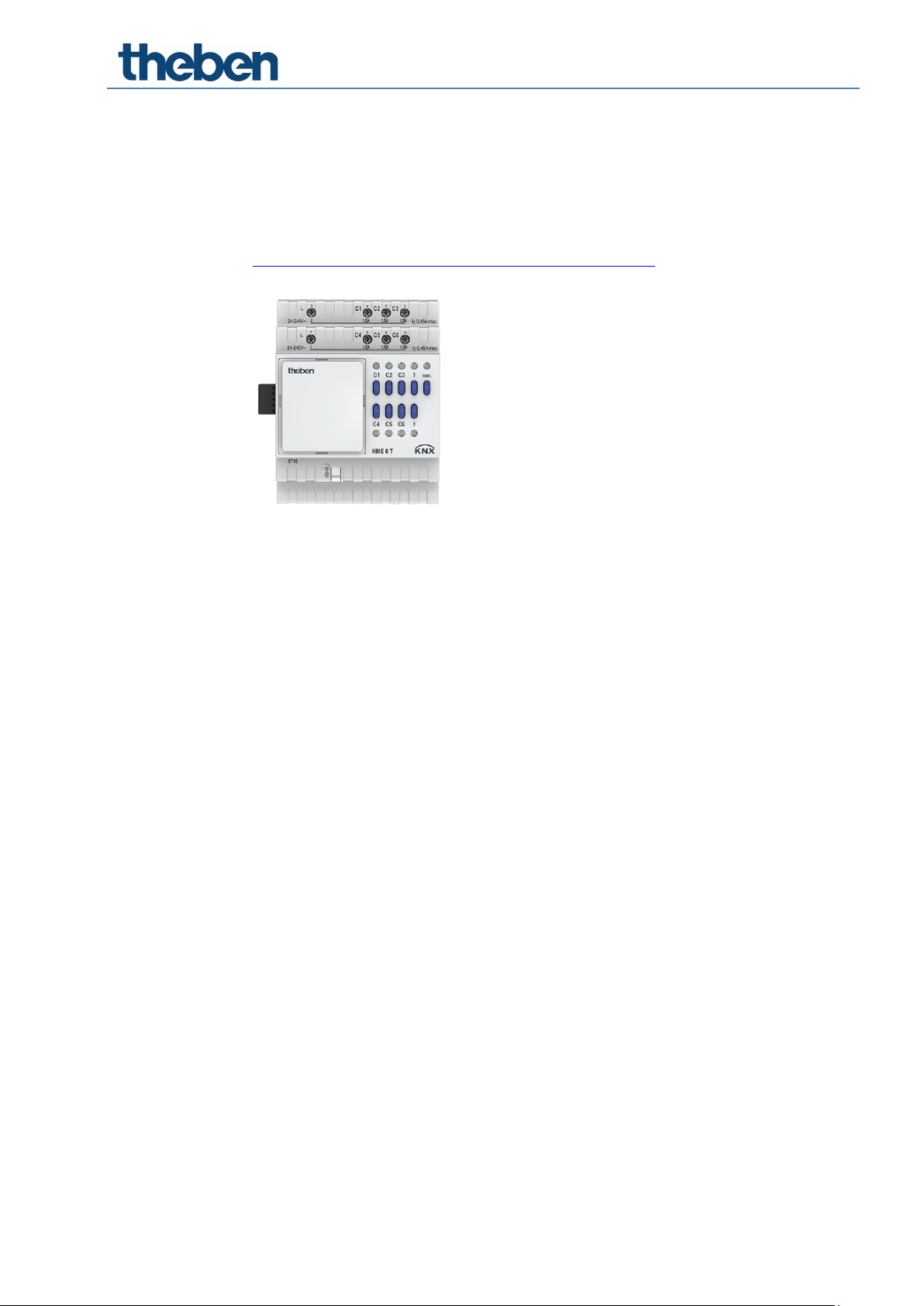
5.2.5 HME 6 T KNX
https://www.theben.de/de/hme-6-t-knx-4930245
The 6-way heating actuator (extension module) of the MIX2 series
controls electronic actuators for heaters or cooling surfaces
With 6 temperature controllers (P/PI) for heating and cooling
For extension to up to 18 channels
With the modes: comfort, standby, night as well as frost/heating
protection
Up to 2 MIX or MIX2 extension modules can be connected to a base
module
Device and KNX bus module can be exchanged independently of each
other
Removable KNX bus module allows devices to be exchanged without
reprogramming
Manual start-up and operation of the actuators are also possible without
KNX bus module
LED switching status indicator for each channel
Manual operation on the device (even without bus voltage)

KNX devices used in the case
Manual for the training case KNX 20
5.2.6 Meteodata 140 S 24V KNX
https://www.theben.de/de/meteodata-140-s-24v-knx-1409201
The weather station detects wind, rain, brightness and temperature.
Additionally, a rain sensor is installed on the top
For fully automatic blinds and sun protection control with automatic sun
position tracking
Sun protection for up to 8 façades via 3 integrated brightness sensors
5.2.7 TA 8 S KNX
https://www.theben.de/de/ta-8-s-knx-4969228
Binary input/binary output push button interfaces: With the 8-way push
button interface, the inputs can detect binary states (via potential-free
contacts) and control indicator lights (LEDs) via the outputs
Free allocation of functions: switch/push button, dimming, blinds,
valuator, sequences, temperature measurement, LED control
2 NTC inputs for actual temperature measurement from -5 °C to +100 °C
They can be installed with conventional push buttons/switches in flush-
mounted boxes.
This manual suits for next models
1
Table of contents


