thermopatch.com
8
4. Operating Instructions
4.1 Operating the NL-33
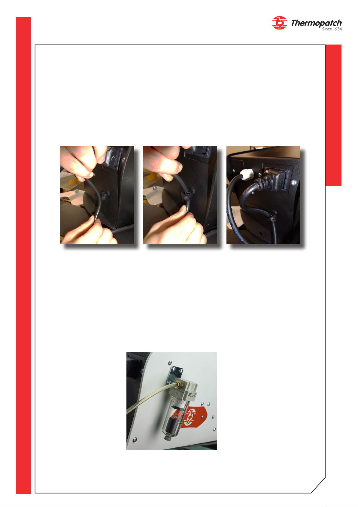
• Switch on the press by pressing the power switch located at the rear.
• Check that the Emergency Stop button is unlocked.
• The touchscreen will show above start page.
• Tap the screen to access the following pages.
• Set the desired temperature according to the chosen type of transfer.
• Set the desired time according to the chosen type of transfer.
• Set the desired pressure by turning the pressure adjustment knob in the middle, below
the display. Turn left to decrease the heat sealing pressure, turn right to increase the
heat sealing pressure.
• Check the set pressure on the manometer which is mounted to the left of the pressure
adjustment knob.
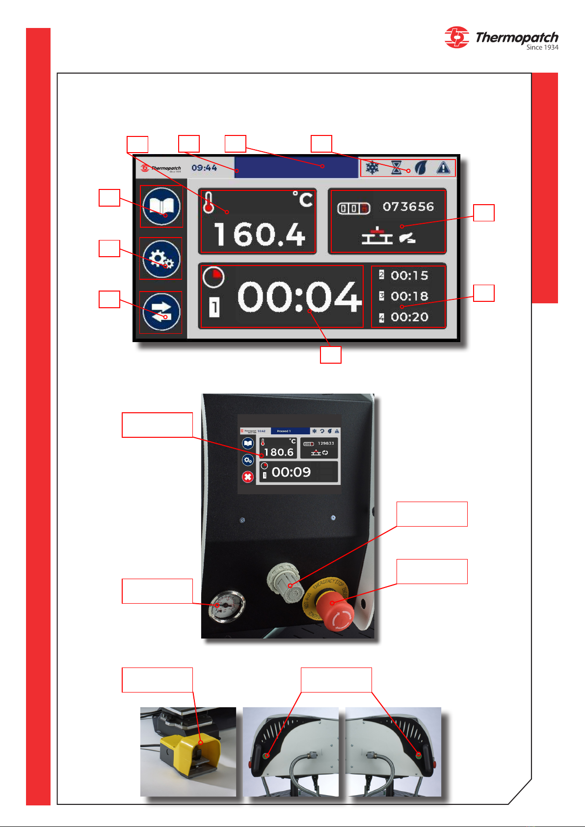
4.2 Operating the control panel
The settings for temperature and time are displayed on the control panel (page 9).
1. Measured temperature and temperature setting (0 to 220 °C):
• The thermometer symbol shows RED when the temperature is above the set value
• The thermometer symbol shows BLUE when the temperature is below the set value
• The thermometer symbol shows WHITE when the temperature is at the set value
2. Time
3. Name of active preset
4. Status bar (HEAT - CYCLE - ECO MODE - WARNING)
5. Daily counter / Working mode
6. Active timer
7. Next timers (4 possible timers)
8. Preset button
9. Settings button
10. Exchange plate button - STOP during cycle .
The green two-hand control buttons on the side and the footswitch allow the start of the
heat sealing cycle. This is only possible when this start page on the touch screen is visible.
For a quick shut down, two modes are available:
• Press the STOP button : the plate goes up, and the press stops moving.
• Press the footswitch or green two-hand control: the plate goes up, moves to the oppo-
site plate and stops moving.
STOP button