Thitronik WiPro III User manual

Revision 1. 6
Thitronik GmbH
g
–
Ec
fö

Installation manual for WiPro III Page 1
GB
Chapter Page Contents
1 Installing the system
1.1 1 Functional description
1.2 2 Installation instructions
1.3 2 Specialfeaturesspecictothevehicle
1.4 3 Accessories
1.5 3 Special functions (volume, anti-jamming)
1.6 4 Preparing for installation
1.7 4 Adjusting WiPro to the vehicle type
1.8 5 Storing wireless components
1.9 5 Deleting wireless components
1.9.1 6 Diagrams
1.9.2 7 Installing the wireless magnetic contacts
1.9.3 7 Rangetest/Diagnosticsmode
1.9.4 7 Installing the wireless gas alarm (accessory)
1.9.5 8 Diagrams
1.9.6 9 Installing the radio cable loop (accessory)
1.9.7 9 Installing and connecting external sirens (accessories)
1.9.8 9 Installing the central unit
1.9.9 10 CAN bus diagnostics
1.9.10 10 Performing an alarm test
2 10 – 15 Connecting the central unit to the vehicle systems
3 Miscellaneous
3.1 16 Technicalspecications
3.2 16 Approvals
3.3 16 Scope of delivery
3.4 17 Troubleshooting/Support
3.5 18 Disposal instructions
1.1 Functional description
The WiPro III alarm system has been developed especially for recreational vehicles.
This system does not use motion sensors, which have to be deactivated when the
vehicle is staying somewhere and are often the cause of false alarms. The result is
a thoroughly user-friendly alarm system which is operated at the touch of a button
and is practically immune to false alarms.
The interior is secured via wireless magnetic contacts on the doors, windows and
hatches. All doors, sliding doors, rear doors and, if necessary, the front lid monitored
by the CAN bus are secured by the CAN bus connection.
The cab doors on vehicles without a CAN bus are secured by the interior lighting.
The system is operated via the original remote key fob or the Thitronik wireless
remote control, depending on the vehicle concerned. If a secured opening is opened
while the alarm system is armed, WiPro (if properly connected) will indicate this by
switching on the integrated siren, sounding the horn (not with all vehicle types) and
activating the hazard indicators. The alarm is active for the legally permissible period
of 30 seconds for the horn and siren and 120 seconds for the hazard indicators. After
expiration of the legally stipulated maximum duration, WiPro III is automatically
armed again.

GB
Installation manual for WiPro III Page 2
1.3 Special features specic to the vehicle
General:Allvehicledoorswhicharemonitoredbythevehiclecomputerrequireno
wireless magnetic contact, since these doors are automatically secured via the CAN
bus when the WiPro unit is properly connected to the vehicle system. This is also the
case with fully integrated vehicles in which the body manufacturer has connected the
door contacts of the basic vehicle.
This is the case if an opened door is displayed on the multi-purpose display.
For some vehicle types (e.g., Sprinter, T5, T6), the horn will only operate when the
ignition is on. The vehicle horn is not triggered by WiPro III in this case. It is
recommended to mount a siren in the engine compartment or to use a back-up siren.
Further information:
http://www.thitronik-automotive.de/en/support/faqs/faq-wipro-iii.html
1.2 Installation instructions
When working on the vehicle electrical system and there is a risk of a short
circuit, the minus pole of the battery must be disconnected. The minus pole
of additional supply batteries must also be disconnected.
Note! When the vehicle battery is disconnected, some of the data from the
vehicle electronic system will be lost. Make sure that you have the radio code
because this will have to be re-entered. Data such as the time are volatile and
must also be re-entered.
Parts which are mounted on the vehicle must be fastened down so they do not
come adrift due to vibrations, sudden braking or other conditions and block vehicle
functions such as the steering system and pedals etc.
Cables must be protected from wearing through or other mechanical stress by
using appropriate fasteners to secure them.
Whenever working on the vehicle, always follow the safety and working
instructions stipulated by the vehicle manufacturer and vehicle trade.
Please read this installation manual carefully to avoid problems during installation.
Incorrect installation can damage both the alarm system and the vehicle. If problems
occur during installation, we will be glad to assist you.
However, assistance is possible only if you have read and understood this manual
completelyandifyouaresucientlyqualiedtoinstallthesystem.
Specialist dealers can obtain vehicle-specic installation documents with precise
specications for connecting the CAN bus, smart indicators, horn and central locking
system evaluation and much more on request. These contain the pin assignments on
the vehicle connectors and the position of the components.

Installation manual for WiPro III Page 3
GB
1.4 Accessories
Also available as accessories are additional wireless magnetic contacts, wireless
remote controls, radio cable loops, wireless gas alarms and a GSM telemetry module
(Pro-nder)forvehicletracking.
By using other wireless magnetic contacts (Item no: 100757 black, 100758
white),itispossibletosecurebaeplates,windows,doors,roofhatchesandeven
roof boxes.
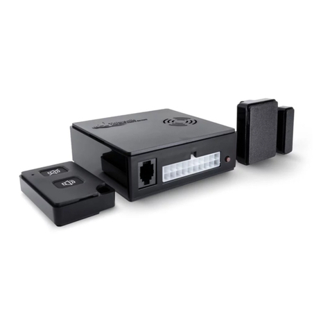
Wireless remote controls (Item: 100756) enable other family members etc.
to control the system and gain access to the vehicle.
By using the radio cable loop (Item no: 100761), you can secure mobile goods
(such as bicycles, motor scooters, surfboards and camping furniture etc.) against
theft outside the vehicle.
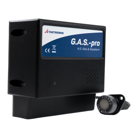
By using one or more wireless gas alarms (Item no: 100759), you can protect
your gas supply from the threat of gas leaks and attacks with narcotic gases. The gas
alarm immediately signals the presence of dangerous gases in the room air to the
WiPro, which, in turn, gives out an alarm.
Pro-nder (Item no: 100699) sends an SMS to up to 10 programmable telephone
numbers in the event of an alarm. Another safety function is that when the supply
battery reaches a critical state, an SMS is dispatched with the latest battery voltage.
Theair-conditioningsystemorheateretc.canalsobeswitchedonoroviaan
SMS.ThealarmsystemcanalsobeswitchedonoroviaanSMS.Statusenquiries
requestinginformationonthestatusoftheWiProandthebatterystateetc.canbe
sent at any time by calling the Pro-nder.
The integrated GPS receiver makes it possible to locate a stolen vehicle.
If the vehicle is stolen, an alarm SMS with information on the vehicle location
and speed is dispatched automatically.
BycallingthePro-nder,thestatusenquirywhichlikewisecontainstheposition,
speed and battery state etc. can also be activated at any time.
1.5 Special functions
Reducing the volume of the internal siren:
To reduce the volume, set switch 8 of the DIP switch (A) to the ON position as shown
in Diagram 2 on Page 6.
Disabling the anti-jamming alarm:
IfyoufrequentlyuseyourvehicleinareaswheretheWiProIIIisexposedtoillegal
traconitstransmissionfrequency,thismayresultinundesiredalarms.
To disable the anti-jamming alarm function, set switch 7 of the DIP switch (A) to the
ON position as shown in Diagram 2 on Page 6.
Protection against “replay attacks”
(possiblefromserialno:0823-014orrmwareversion5.8)
To prevent the control of the WiPro III via the car key, set switch 5 of the DIP switch
(A) in sketch 2 on page 6 to position ON.
The evaluation of the vehicle doors nevertheless takes place.
Installation manual for WiPro III Page 4
GB
1.6 Preparing for installation
Make sure you have the tools and materials listed below:
- Cross-head screwdriver - Crimping pliers
- Voltmeter - Cordless screwdriver
- 8mm drill bit - Socket set
- Insulating tape - Butt connectors
- Ring terminals - Cable ties
- Shrink sleeve if necessary - Cleaning cloth for degreasing
- Cleaning agent or degreaser
Choose a suitable place for installing the central unit, the wireless magnetic contact(s)
and other accessories.
Accessories such as the wireless magnetic contacts, wireless gas alarm and
radio cable loop should be assigned prior to installation. (see 1.8)
1.7 Adjusting WiPro to the vehicle type
Open the casing of the central unit (A) by gently levering up the casing cover as shown
in Diagram 1 on Page 6.
Set the DIP switch (A) in Diagram 2, Page 6 according to Table 1. If your vehicle is
not on the list or older, connect it in the usual way (see universal connection diagram,
Page 11) and make sure that switches 1–4 are in the o position.
The settings must be made with the circuit de-energised. Make sure that neither
the20-pinplugnortheplugforthePro-nderarepluggedin.
Table 1
Other types of vehicles can be found at www.thitronik-automotive.de/en/support/faqs/faq-wipro-iii.html
Vehicles from 2006
and later Years of
manu-
facture
Switch 1 Switch 2 Switch 3 Switch 4
Fiat Ducato
Citroen Jumper
Peugeot Boxer
Iveco Daily
2006
and later o on o o
Ford Transit 2006
and later on on o o
Mercedes Sprinter
VW Crafter 2006
and later on o o o
Renault Master
Opel Movano
Nissan Interstar
2006
to 2011 on on on o
New Renault Master 2011
and later o on on o
VW T5 2006
to 2009 on o on o
VW T5 Facelift 2010
and later on o o on

Installation manual for WiPro III Page 5
GB
1.8 Storing wireless magnetic contacts, wireless remote controls, etc.
!! As supplied, no wireless magnetic contacts, etc. are stored !!
If the instructions in this chapter are not carried out, the alarm system can-
not interpret the signals transmitted by the wireless components, and the
wireless components cannot trigger an alarm.
Plug in the 20-pin plug “A” (Diagram 1, Page 6).
Now, hold down the button “B” on the front of the casing (Diagram 1, Page 6)
until the central unit gives a long beep and the status LED comes on.
Another option is to activate Assign mode as described in the operating instructions.
Now activate each wireless magnetic contact to be stored as shown in Diagram 4
(keepingbothpartsawayfromeachotheruntiltheLED(“C”)lightsupbriey).
Or press one of the buttons on the wireless remote control as shown in Diagram 5.
The wireless gas alarms must be switched on to store them and radio cable loops
must be removed from the holder.
After each storing procedure has been successfully carried out, a short beep will
sound,andthestatusLEDwillgooutbriey.
ToterminateAssignmode,brieypressthebutton“B”onthefrontofthecasing
again. The central unit will sound a double beep, and the status LED will go out.
1.9 Deleting wireless components
Transmitters can only be deleted by erasing the memory.
Hold down the button “B” on the front of the casing (Diagram 1 on Page 6) while
unplugging the 20-pin plug until the central unit gives a long beep. All the transmit-
ters are now erased.
Important!
The procedure for subsequently adding wireless components, without access
to the main unit, is described in Chapter 2 of the Operating Instructions.

Installation manual for WiPro III Page 6
GB
Diagram 1 Diagram 2
A
Diagram 3 Diagram 4
Diagram 5
B
A
1.9.1 Diagrams
max. 22 mm
ABAB
C
<<<>>>
GSM module
connection
Common pin 2
Common pin 3
indicator input
NO (COM)
Antenna
Horn
Ignition
Hazard indicators
external LED
(gnd
)
external LED +
NO
–12V (gnd)
Right indicator
Left indicator
Siren + 12 V
Siren gnd
CAN high
CAN low
+12V DC
Common pin 1
Diagram 6
C

Installation manual for WiPro III Page 7
GB
1.9.2 Installing the wireless magnetic contacts
Choose the places where you want to install the wireless magnetic contacts.
The transmitters can be installed both on the window and the frame (see diagrams
on Page 8). The distance between the transmitter (Diagram 3, Part A, Page 6)
and magnet (Diagram 3, Part B, Page 6) can be around 22 mm. A larger distance
activatesthetransmissionprocess(LEDlightsupbriey.Diagram4,C)andtriggers
the alarm when the system is activated.
Before installing the wireless magnetic contacts, carry out a range test using the
adhesive pads.
Inordertodoso,xthetransmitterwhichisalreadyassignedandthemagnets
to the places you have chosen using adhesive tape and follow the instructions
under 1.9.3.
The contact surface must be clean, dry and free of grease. Treat with suitable
cleaning agent beforehand.
Donotuseonsurfacesattemperaturebelow15°C.
Theadhesivepadsreachtheirnalstrengthafterapprox.24hours.
If installed on the rear storage locker, use the mounting adapter
(Item no. 100428 black or 100729 white) to optimize the transmission
and bridge larger gaps.
1.9.3 Range test / Diagnostics mode
Brieypressthebutton“B”onthecentralunit(Diagram1Page6).ThestatusLED
onthecableassemblystartstoash.WiProIIIisnowinDiagnosticmode.
The central unit acknowledges every transmission process received from
an assigned transmitter with an acoustic signal.
If there is no acoustic acknowledgement tone, the transmitter is not assigned
(repeat 1.8) or shielded by metal parts. In this case, choose another place to mount
the transmitter or use the mounting adapter (Item no. 100428 or 100729).
ToterminateDiagnosticsmode,brieypressthebutton“A”again.
The LED goes out.
1.9.4 Installing the wireless gas alarm (accessory)
Choose a suitable place to mount the wireless gas alarm.
The place where it is mounted should not be in the direct vicinity of the heater
outlets or where there are lead-acid batteries. Mounting it in the direct vicinity
of strong cleaning agents, petrol and other fuels should also be avoided.
The ideal height of installation is at the lowest point of the vehicle just above the
oor(approx.10–20cm).
Now carry out a range test with the wireless gas alarm, as described under 1.9.3.
Mount the wireless gas alarm using the template in the wireless gas alarm manual
andconnectthesupplyvoltage.(brown=+12V/white=earth)

Installation manual for WiPro III Page 8
GB
1.9.5 Diagrams
Option lying
on the right
It is possible to mount the transmitter
casing in a lying position (on the left or,
rotated180°,ontheright)orstanding
on the side – depending on the frame
andtheavailablespace/thedistances
to the pane. When the transmitter
casing is rotated, the circuit board with
the transmit LED, the reed sensor and
the transmitter cover will keep their
orientation to the magnet.
Option
standing
Option lying
on the left
Window frame
Window pane
Window pane
For instance, Dometic AGP7 or Seitz AGS5
and similar products
Window frame
Window pane
Option
window pane
If the available space does not allow for the transmitter
to be installed on the window frame, the transmitter
can also be mounted on the window pane as shown
on the right.
If installation is not possible using the included adhesive
pads,youcanalsousescrewstoxthetransmitter
housinginplace.Youwillndscrewpositionmarks
underneath the circuit board.
Please scan the QR code for additional
information and video instructions.
www.thitronik-automotive.de/support.html
Transmit LED
Reed sensor
Transmitter casing Magnet
Transmitter
cover
Window frame
Window pane
Window frame

Installation manual for WiPro III Page 9
GB
1.9.6 Installing the radio cable loop (accessory)
Choose a suitable place for installation at the back of the vehicle or on one of the
sides. You can also obtain further holders as accessories (Item no: 100649) to use
the cable loop for other areas of the vehicle.
Now carry out a range test with the radio cable loop, as described under 1.9.3.
Removing the cable loop from the holder triggers a transmission process.
Using the screws provided, fasten the holder of the cable loop to where you want
to place it. If you drill through the outer skin of the vehicle, seal the drilled holes
withSikaextopreventthepenetrationofmoisture.
1.9.7 Installing and connecting external sirens (accessories)
Choose a suitable place for mounting in the vehicle interior or in the engine
compartment. When laying the cable, make sure that it does not lie within the range
ofmovementofanymovingpartsofthevehicle,thatitleavessucientdistancefrom
hot engine components and cannot be exposed to wear damage due to sharp edges.
The siren must not be detached through vibration, braking suddenly or other condi-
tions and thereby impede the roadworthiness of the vehicle. As with the cables, the
sirenmustbesucientlyfarawayfromhotenginecomponents.
Siren without rechargeable battery
Connecttheredandtheblackcableofthesirentothewhite(Pin15/siren+12V)and
thewhite/blackcableofthecableassembly,respectively.
Back-up siren with rechargeable battery
The back-up siren has an integrated rechargeable battery which is constantly charged
via the red (+12 V) and black (earth) conductors. These conductors must be connect-
ed to the on-board power supply. The back-up siren sounds if there is a power failure
(only when it is activated via the key switch).
The white wire of the back-up siren must be connected to the white wire of the central
unit(Pin15/siren+12V).Thebluewire(negativetrigger)oftheback-upsirenisnot
used (please insulate it). The back-up siren sounds when there is a positive voltage
on the white wire (only when it is activated via the key switch).
1.9.8 Installing the central unit
Choose a suitable place in the vehicle interior to mount the central unit where the
unitisprotectedagainstquickaccess.Ideally,chooseaplaceforinstallingitnearto
the central electronic unit of the vehicle in order to keep the cable lengths as short
as possible. You can use both the provided adhesive pads or the plastic parts, which
are also included, to mount the unit. You need to apply some adhesive to the plastic
angesbeforeyoucanxthemtothecasing.Whenlayingthecables,makesurethat
they are not within the range of movement of moving parts of the vehicle or pedals
etc.

Installation manual for WiPro III Page 10
GB
1.9.9 CAN bus diagnostics
TondoutwhethertheWiProCANbusisreceivingdata,activateDiagnosticsmode.
Brieypressthebutton“B”onthecentralunit(Diagram1Page6).ThestatusLED
onthecableassemblystartstoash.WiProisnowinDiagnosticmode.
While WiPro is in Diagnostics mode, operate the remote key fob of the vehicle
oractivatethewarninglights.BothleadtodatatracontheCANbus,whichcan
be evaluated.
IfCANbusdataarebeingreceived,thestatusLEDashesorickers
depending on the data transfer rate of the BUS system.
If the status LED shows no response, the connection is faulty or CAN H and CAN L
have been swapped over.
1.9.10 Performing an alarm test
After the central unit has been installed and connected to the vehicle systems
(Chapter 2) a test alarm should be carried out with each assigned transmitter
(wireless magnetic contact, radio cable loop and wireless gas alarm).
Activate WiPro and open one of the assigned wireless magnetic contacts.
Thesirensounds,thevehicleindicatorsashandthehornsounds,depending
on the type of vehicle.
Repeat the process with each of the installed and assigned transmitters.
To test the alarm for a cable loop, remove it from the holder with the system activated.
To carry out an alarm test with a wireless gas alarm, switch it on and wait until the
preheatingphaseisover(powerlampashesgreen).Floodthewirelessgasalarmwith
lightergas.Thepowerlampashesquickly,andWiProIIIgivesanalarmasdescribed
in the user manual.
To test the alarm with the cab doors, open one of the doors from the inside when
the WiPro is activated.
!!A test alarm with the driver’s cab doors (if connected to the input for
the interior lighting) is not possible until at least 60 seconds after arming
the system!!
2 Connecting the central unit to the vehicle systems
Connect the WiPro III cable according to the plug assignment diagram on Page 11
and using the connection diagrams on Pages 12 to 15.
All connections must be made with the circuits de-energised.
To avoid short circuits or malfunctions, insulate the ends of the wires which are
not used.

Installation manual for WiPro III Page 11
GB
Pin Colour Abbre-
viation Function Special features
1 black bk Earth (Terminal 31)
2 brown br Alarm input NO Activated when the system is armed and disarmed. Input for
conventional gas alarm (G.A.S.-pro). NO contact. Insulate in
green when not in use!
3 green gn Alarm input COM
4 red r Status LED White plug connector is to connect to the counterpart of the status LED.
5 black bk Status LED
6red/pink r/p Smart indicator Wattless indicator controller
(seevehicle-specicconnectiondiagrams)
7 yellow ye Ignition (Terminal 15)
8 beige be Common pin 3 See connection diagram for Renault Master and similar models
9 pink p Horn signal Wattlesshorncontroller(seevehicle-specicconnectiondiagrams)
10 white wh Antenna Do not shorten or wind up!!!
11 red r +12/24V
(Terminal 30)
12 grey gr Left indicator
13 grey/black gr/bk Common pin 4 Not used (please insulate!)
14 grey gr Right indicator
15 white wh Siren +12 V Connect to red siren cable or to white cable of the back-up siren.
16 white/black wh/bk Siren earth Connect to black siren cable.
17 white/orange wh/or CAN high Mustonlybeconnectedbyqualiedpersonnel!!!
18 violet/orange vt/or CAN low
19 blue/black bl/bk Common pin 2 Input for interior lighting. See Universal connection diagram.
On Ford Transits, for evaluating the central locking system signals
(Controlling the WiPro with remote key fob).
See connection diagram for Ford Transit
20 blue bl Common pin 1
Specialist dealers can obtain vehicle-specic installation documents with precise specications for connecting the CAN bus,
smart indicators, horn and central locking system evaluation and much more on request. These contain the pin assignments
on the vehicle connectors and the position of the components.
Pin assignment of the 20-pin plug connector

Installation manual for WiPro III Page 12
GB
Battery
+-
COM
NO
bl
br
gn
Ignition ye
bk
r
wh
r
gr
gr
r
bk
F10A
Interior lighting
Status LED
Siren
Indicators
Door contact
bl/bk
wh/bk
WiPro III
bk
Pin no: 10 19 20 2 3 7 16 15 4 5 12 14 11 1
Connection
for G.A.S.-pro
if used
Antenna. Do not shorten or wind up!
Indicators
wh
Specialist dealers can obtain vehicle-specic installation documents with precise specications
for connecting the CAN bus, smart indicators, horn and central locking system evaluation and
much more on request. These contain the pin assignments on the vehicle connectors and the
position of the components.
Universal connection diagram
This connection diagram shows the available connections for WiPro on vehicles
without CAN bus technology.

Installation manual for WiPro III Page 13
GB
Battery
+-
COM
NO
wh
br
gn
Ignition ye
bk
r
wh
wh/or
vt/or
r
r
bk
F10A
Status LED
Siren
wh/bk
r/p
Hazard indicators
WiPro III
Horn button
bk
CAN-H CAN-L
Connection
for G.A.S.-pro
if used
Antenna. Do not shorten or wind up!
Pin no: 10 19 20 2 3 7 16 15 6 9 4 5 11 1 17 18
p
bl/bk
bl
Connection
to original
central
locking
system.
Signal
evaluation.
open
closing
Battery
+-
COM
NO
wh
br
gn
Ignition ye
bk
r
wh
r
r
bk
F10A
Status LED
Siren
wh/bk
r/p
Hazard indicators
WiPro III
Horn button
bk
wh/or
vt/or
CAN-H CAN-L
Connection
for G.A.S.-pro
if used
Antenna. Do not shorten or wind up!
Pin no: 10 2 3 7 16 15 17 18 9 4 5 11 1 6
p
Connection diagram for: Ford Transit from 2006 onwards
Connection diagram for: Fiat Ducato, Citroen Jumper and Peugeot Boxer from
2006 onwards and Iveco Daily from 2006 onwards
Deadlock-function
required!

Installation manual for WiPro III Page 14
GB
r/p
Hazard indicators
Battery
+-
COM
NO
wh
br
gn
Ignition ye
bk
r
wh
r
r
bk
F10A
Status LED
Siren
wh/bk
WiPro III
bk
Connection
for G.A.S.-pro
if used
Antenna. Do not shorten or wind up!
Pin no.:10 8 19 20 2 3 7 16 15 4 5 6 11 1
bl/bk
bl
Connection
to original
central
locking
system.
Signal
evaluation
open
closing
Interior lighting
Door contact
be
Edge 0V to 12V activates alarm!
Battery
+-
COM
NO
br
gn
Ignition ye
bk
rwh
r
gr
gr
r
bk
F10A
Status LED
Siren
Indicator lights
wh/bk
WiPro “all in one”
bk
Pin no: 10 2 3 7 16 15 4 5 12 14 11 1 17 18
Connection
for G.A.S.-pro
if used
Antenna. Do not shorten or wind up!
Indicator lights
wh
wh/or
vt/or
CAN-H CAN-L
With Sprinters and Crafters, all four indicators
are triggered separately. Since WiPro only has
two outputs, these must be distributed among
4 indicators with diodes. A diode distributor
is available as an accessory to simplify the
connection. (Item no: 100455).
Isalreadyincludedinthevehicle-specicset.
Connection diagram for: Mercedes Sprinter, VW Crafter from 2006 onwards
Connection diagram for: Renault Master, Nissan Interstar and Opel Movano from 2006 on-
wards

GB
Installation manual for WiPro III Page 15
Connection diagram for: Renault Master from 2011 onwards
Battery
+-
COM
NO
wh
br
gn
Ignition ye
bk
r
wh
r
r
bk
F10A
Status LED
Siren
wh/bk
r/p
Hazard indicators
WiPro III
Horn button
bk
wh/or
vt/or
CAN-H CAN-L
Connection
for G.A.S.-pro
if used
Antenna. Do not shorten or wind up!
Pin no: 10 2 3 7 16 15 17 18 9 4 5 11 1 6
p
Connection diagram for: VW T5 from 2006 onwards
Battery
+-
COM
NO
wh
br
gn
Ignition ye
bk
r
wh
r
r
bk
F10A
Status LED
Siren
wh/bk
r/p
Hazard indicators
WiPro III
Horn switch
bk
wh/or
vt/or
CAN-H CAN-L
Connection
for G.A.S.-pro
if used
Antenna. Do not shorten or wind up!
Pin no: 10 2 3 7 16 15 17 18 9 4 5 11 1 6
p

Installation manual for WiPro III Page 16
GB
3.1 Technical specications
Main unit
Power supply (Uin): 9–30V
Sirenoutput: 9-30V(Uin)/1A
Indicator output: 60W
Current consumption: approx. 11 mA
Assignable transmitters max: 100
Receivingfrequency: 868.35Mhz
Number of codes: >4 billion. (>4,000,000,000)
Temperaturerange: –10°Cto+80°C
Interfaces: RJ11(outputforPro-nderforalarmforwarding)
CAN bus interface
Remote control 868, magnetic contact 868
Transmission power: <10 mW
Range max: 75 m in the open
Batterytype(transmitter): CR2032(buttoncell/3V)
Battery life (transmitter): approx. 2 years
Transmittingfrequency: 868.35Mhz
Number of codes: >4 billion. (>4,000,000,000)
Temperaturerange: –10°Cto+60°C
Caution!
Risk of explosion if battery is incorrectly replaced!
Dispose of used batteries according to the instructions.
3.2 Approvals
E1This alarm system for recreational vehicles is tested and approved according
to ECE regulation no. 10, revision 03.
3.3 Scope of delivery
WiPro III central unit, connection cable, wireless remote control 868, wireless
magnetic contact 868 with adhesive pads, fuse holder with fuse, status LED with con-
nection cable, 1x warning sticker, installation manual and operating instructions
Thescopeofdeliveryvariesforvehicle-specicsets.Dependingonthevehicletype
thecableassemblyisequippedwithothercables,andwirelessremotecontroland
wireless magnetic contact may not be included.

Installation manual for WiPro III Page 17
GB
3.4 Troubleshooting
If the following section does not resolve or describe the problem,
please contact our Technical Support Department: +49(0)431-66 66 811
Problem
WiPro does not respond to the command from the remote key fob
but the central locking system is working.
Possible causes
The vehicle is not listed in Table 1 under 1.7.
The DIP switch is not coded as described in Table 1.
CAN high and CAN low have been swapped over.
The CAN connection is not correctly assigned.
Problem
When arming the system, an open wireless magnetic contact
is signalled although all the contacts are closed.
Possible causes
WiPro has been isolated from the operating voltage and
no longer “knows” the state of one or more contacts.
Solution: open and close all the contacts several times.
Problem
A contact is not being received, despite the fact that the distance
to the central unit is short.
Possible causes
The contact is not assigned.
Solution: Assign contact.
The receiver antenna is located behind shielding metal or is in contact
with the metal structure which is impeding reception.
Solution: Change the position of the central unit or the antenna.
There is shielding metal between the transmitter and the unit,
such as a gas box etc.
Solution: Change the position of the transmitter.
Problem
Reception from contacts on rear storage lockers is not reliable.
Possible causes
Thecontactismountedonametalmaterial,whichhasanegativeeect
on the antenna properties.
Solution: Use mounting adapter (art. no.: 100428).

Installation manual for WiPro III Page 18
GB
3.4 Disposal instructions
When the unit is no longer in use, please do not dispose of it
with household waste. Municipal recycling centres have suitable
containersforthedisposalofelectronicequipment.
Take the packaging materials to the recycling centre.
Installation details
To make servicing the system easier later on, you can make a few notes below
whichyoumayndhelpful.
Number of wireless Number of
magnetic contacts: handheld transmitters:
Number of wireless Number of
gas alarms: wireless cable loops:
Position of the
central unit:
Position of the
GSM module:
Position of the
GPS antenna:
Separate fuse installed: No Yes Rating (A)
Position of the fuse:
Vehicle fuse used: No Yes Rating (A)
Fuse no: Position of the fuse:
Serial number of the unit:
Other matters:

Revision 1.6
DE
GB
FR
NL
IT
DK
SE
Installationshandbuch
Installation manual
Manuel d’installation
Montagehandboek
Manuale di installazione
Installationshåndbog
Installationsbok
Hersteller/Manufacturer
Thitronik GmbH
Redderkoppel 5
D 24159 Kiel (Germany)
www.thitronik.de
Tel.: +49 (0)431-66 66 811
Fax: +49 (0)431-66 66 827
WiPro III
10R - 036873
E1
Thitronik GmbH
g
–
Ec
fö
Other manuals for WiPro III
3
Table of contents
Other Thitronik Security System manuals

Thitronik
Thitronik Power Alarm System User manual

Thitronik
Thitronik G.A.S.-pro User manual

Thitronik
Thitronik WiPro III User manual

Thitronik
Thitronik C.A.S. III Operating instructions

Thitronik
Thitronik THA-2-00015 User manual

Thitronik
Thitronik GBA-I User manual

Thitronik
Thitronik G.A.S.-pro III User manual
Popular Security System manuals by other brands

PSP Security
PSP Security AccuFACE EFR-T3 Series Quick installation guide

ADEMCO
ADEMCO LYNXR Programming manual

Honeywell
Honeywell Fire Lite Alarms SWIFT Installation & quick start guide

Maple Systems
Maple Systems cMT3102X Series Installtion Instructions

Gemini
Gemini GEM-P9600 Programming instructions

Telexper
Telexper tXPER user manual