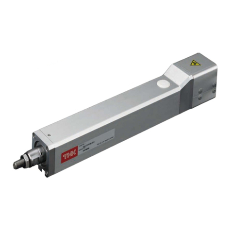
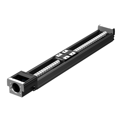
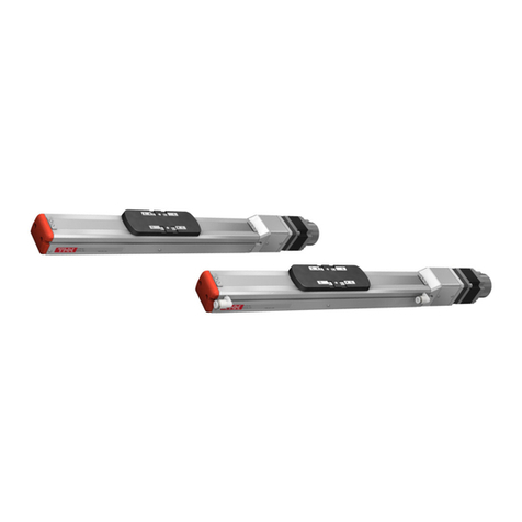
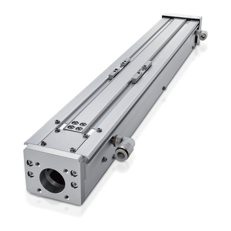
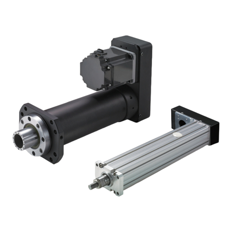
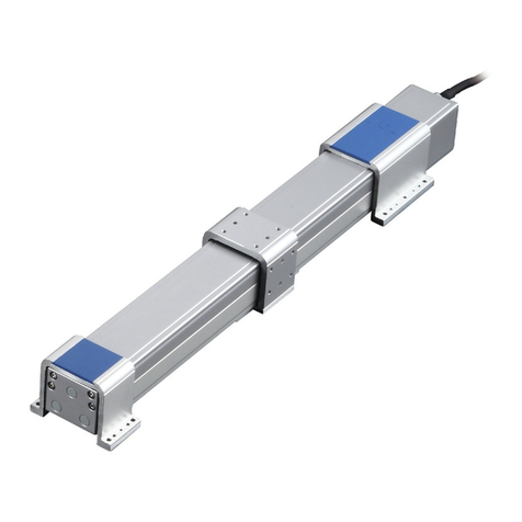
THK ET Series User manual

INSTRUCTION MANUAL
ET
THK Electrical Actuator Economy Series
No.1050-3(0)E

iET
Table of Contents
1. Introduction 2. Installation 3. Wiring
1. Introduction
1-2
1-1 Acknowledgment 1-2
1-2 About this manual 1-2
1-3 How to use this product 1-3
1-4 About product support 1-3
1-5 About related instruction manuals 1-3
1-6 Product and company information 1-3
2. Safety precautions 1-4
2-1 About ranks of precautions 1-4
2-2 About description of precautions 1-4
2-3 Safety precautions 1-5
3. System configuration 1-6
3-1 System configuration diagram 1-6
4. Flow until using the product 1-7
1. Check products 2-2
1-1 Check the package contents of ET 2-3
1-2 Names of individual parts and functions 2-7
1-3 Store and dispose of products 2-9
2. Precautions on use 2-10
2-1 Precautions on use of ET 2-10
3. How to install 2-11
3-1 Installation environment 2-11
3-2 Setting of ET 2-12
1. How to wire 3-2
1-1 Entire wiring 3-3
1-2 Connect actuator cable 3-4

ii ET
Table of Contents
4. Maintenance and Warranty
5. Technical Materials
1. Maintenance 4-2
1-1 Daily inspection 4-2
1-2 Periodical inspection 4-3
1-3 How to apply grease 4-4
1-4 Check points when restoring from the long-term suspension 4-8
2. Repair/Replacement 4-9
2-1 How to replace the timing belt 4-9
3. Product warranty 4-13
3-1 Free warranty period 4-13
3-2 Usage conditions (range) 4-13
3-3 Warranty scope 4-13
3-4 Exclusion of warranty liability 4-14
3-5 Delivery conditions 4-14
1. Motor mounting method 5-2
1-1 Motor mounting example 5-2
2. Cables 5-6
2-1 Connection cable 5-6
3. Materials Required for Selecting 5-7

1-1 ET
1. Introduction ………………… 1-2
1-1 Acknowledgment…………………………… 1-2
1-2 About this manual ………………………… 1-2
1-3 How to use this product…………………… 1-3
1-4 About product support …………………… 1-3
1-5 About related instruction manuals ……… 1-3
1-6 Product and company information ……… 1-3
2. Safety precautions ………… 1-4
2-1 About ranks of precautions ……………… 1-4
2-2 About description of precautions ……… 1-4
2-3 Safety precautions ………………………… 1-5
3. System configuration ……… 1-6
3-1 System configuration diagram…………… 1-6
4. Flow until using the product 1-7
1. Introduction
This section includes
introduction about the
product and this manual.
This section includes
general precautions to
follow when using the
product.
Be sure to read this
section before use and
observe the precautions.
This section includes
introduction about
peripheral devices to be
used with this product.
This section describes
installation and setting
processes to make this
product ready for use.
About this chapter
This chapter describes the overview of the product.
This chapter includes information that we want you to check and understand before working with the product.

1. Introduction
1-2 ET
1-1 Acknowledgment
Thank you for purchasing our product.
This product is a lightweight, compact, and reasonably-priced actuator which ensures a long-term
maintenance-free operation.
This product is designed and manufactured to be incorporated in devices with a wide range of
applications including conveyance systems, implementing equipment, automated assemblers,
positioning equipment and more.
We hope our creative inventions and unique technologies contribute to your further prosperity.
1-2 About this manual
1-2-1 Intended audience
The person in charge of designing embedded systems of the product and installing, wiring, and
maintaining the product, and the person who actually uses the product.
1-2-2 Using this manual
This manual describes correct handling methods and precautions for the product.
For the maximum performance and long life of the product, carefully read and understand this manual to safely and
correctly use the product.
If you use the printed version of this manual, be sure to keep it in the place that the audience can refer to it when needed.
1-2-3 Notice and attention
lDo not use or handle the product in the ways that are not described in this manual.
lDo not reproduce, reprint, or lend the whole contents or a part of this manual without permission.
lPlease note that the description in this manual is subject to change without prior notice in the
future, due to improvements of the product or other reasons.
We have made all possible efforts to make the content of this manual accurate. However, if you
find any mistake or uncertainty in this manual, please contact THK.
For the following information, please contact THK.
lDrawings throughout this manual are only intended as typical examples, and may differ from your product.
lNote that THK shall not be liable for any result incurred by applying this manual, regardless of the reason.
lThis manual is also applied to custom products. However, the descriptions provided in the delivery specification
drawings or delivery specification documents of those custom products take precedence over this manual.
×Custom products represent the products that have different materials and specifications from
those of the standard products on catalogs.
1-2-4 Notation of this manual
Notes that can lead to unsatisfactory functions, errors, or damages of the product if not observed while
using the product.
Supplementary information for the description.
Reference information for the description.
1.
Introduction
Important
Supplement
Reference

1. Introduction
1.
Introduction
1-3 ET
1-3 How to use this product
lThis product must not be used for the devices or systems that are used under the situations that
may be fatal to human life.
lIf you consider using this product for special applications such as passenger movement vehicle,
medical, aerospace, nuclear power, and electric power devices or systems, be sure to consult
with THK in advance.
l
This product is manufactured under the strict quality control, however, that does not mean that the product
is free from failure. For applications to the equipment that may suffer serious accidents or loss from the
failure of this product, install safety devices or backup devices that prevent such serious accidents or loss.
1-4 About product support
For the following information, please contact THK.
lTechnical support for this product
1-5 About related instruction manuals
lWhen you use the actuator ET, read the following instruction manuals as necessary.
• Controller series Driver controller TSC
• Controller series Setup tool D-STEP
If you purchase this product with a motor, TSC is the applicable driver controller. Please note that driver controllers
other than the above cannot be used. This excludes installations of the motor specified by the customer.
1-6 Product and company information
To find the latest product and company information, we recommend you to periodically
access our website.
lWebsite URL: https://www.thk.com
lTechnical support website URL: http://www.tech.thk.com/
Important

1. Introduction
1-4 ET
2-1 About ranks of precautions
This manual uses the classifications of “Danger,” “Warning,” and “Caution” for warning indications
for safety matters.
2-2 About description of precautions
Precautions are classified as “Prohibition,” “Instruction,” and “Precaution” according to the action.
This mark indicates
“prohibition” of the
action.
This mark indicates
“instruction” for
the action.
This mark indicates
“caution” about
the action.
Prohibited Do not
disassemble
Obligatory Provide grounding
connection
Caution Caution -
Electrical shock
Caution -
Flammable
Caution - High
temperature
Caution - Getting
caught
Danger Erroneous handling may urgently cause death or
serious injury to a person
Warning Erroneous handling may cause death or serious injury
to a person
Caution Erroneous handling may cause injury to a person or
property damage only
2.
Safety precautions

1. Introduction
2.
Safety precautions
1-5 ET
2-3 Safety precautions
While the actuator is operating or
operable, do not enter the working
area of any moving part including
the load.
Otherwise, it may cause you to touch
the moving part and get injured.
If the product fails or any abnor-
mality is observed, shut down the
power of the driver controller TSC.
Such abnormality may cause a
malfunction of actuator, resulting in
damage or injury.
Do not touch the internal part of
the driver controller TSC.
Otherwise, it may cause electric shock.
Do not damage, tuck, or apply
excessive stresses on the cable.
Otherwise, it may cause electric shock.
Do not modify, disassemble, or
alter the product.
Otherwise, it may cause injury or
failures.
Prohibited
Obligatory
Caution -
Electrical shock
Do not
disassemble
During the operation, or for a while
after turning the power off, do not
touch the driver controller TSC, or
motor cover because they should
be hot.
Otherwise, it may cause burns.
Do not impact the product and
do avoid rough handling such as
throwing it.
Otherwise, it may cause the failures or
damage that leads to injury.
Do not frequently switch the power
between on and off.
Otherwise, it may generate heat from
the internal parts of the driver controller
TSC, which results in fault or burns.
Do not set the speed or
acceleration setting or place the
load on the table that exceed the
actuator specification.
Otherwise, it may cause motor failure,
which leads to unexpected accidents
or damages.
If an alarm is generated, remove
the cause, check the safety, de-
activate the alarm, and restart the
operation.
Failure to do so may result in failure,
which leads to injury.
Use this product with a combina-
tion that is specified beforehand.
Otherwise, it may cause fire or failures.
Observe the specified input
voltage.
Otherwise, it may cause fire or failures.
Caution - High
temperature
Prohibited
Obligatory
Caution -
Flammable
Warning
Caution

1. Introduction
1-6 ET
3-1 System configuration diagram
lThe diagram below shows the specification of a combination with the driver controller TSC.
lCables for connecting the devices indicated with ★should be prepared by the customer.
3.
System configuration
PC (D-STEP) (-> ×1)
Host controller
Emergency
stop switch
(This should
be prepared by
the customer.)
(-> ×2)
Driver controller
TSC
Actuator cables are
provided with the main unit.
(-> P.5-6)
24 VDC power
★
★
★Power supply
should be prepared
by the customer.
Power connector is
provided with TSC.
(-> ×2)
CN1
CN2
CN4
CN3
CN5
PC communication
cables are provided
as an option.
(-> ×2)
★
I/O connector for CN1
is provided with TSC.
I/O cables are provided
as an option.
(-> ×2)
★
×1 See the separate D-STEP Instruction Manual.
×2 See the separate TSC Instruction Manual.
×When you use 10 m actuator cables,
please install a noise filter for the TSC
power supply.
RSAN-2003 from TDK-Lambda is
recommended for the noise filter.
Actuator
★
Wire to the I/O
connector of sensor
CN1.

1. Introduction
1-7 ET
1. Safety Check
(1) Safety statement check -> P.1-4
(2) Safety check of the installation location
-> P.2-11
(3) Installation check -> P.2-12
2. Preparation (1) Preparation of required devices -> P.1-6
(2)
Package contents check
->
P.2-3 to 2-9
3. Installation (1) Installation environment check -> P.2-11
(2) Installation -> P.2-11 to 2-19
4. Wiring (1) Connection between each device and
cable -> P.3-2 to 3-6
5.
Trial Run and Adjustment
(1) For details of setup tool preparation and
program input, see the separate D-STEP
Instruction Manual.
6. Setup tool setting (1) For details of setup tool setting, see the
separate D-STEP Instruction Manual.
4.
Flow until using the product

2-1 ET
2. Installation
This section describes the
package contents check
and parts of this product.
This section describes the
installation procedures of
this product.
About this chapter
This chapter describes how to check the package contents and to install it to the machine and facilities.
This section is primarily intended for those in charge of installation of this product to a machine and facilities.
1. Check products ……………… 2-2
1-1 Check the package contents of ET …… 2-3
1-2 Names of individual parts and functions 2-7
1-3 Store and dispose of products…………… 2-9
2. Precautions on use ……… 2-10
2-1 Precautions on use of ET ………………… 2-10
3. How to install ……………… 2-11
3-1 Installation environment ………………… 2-11
3-2 Setting of ET ………………………………… 2-12
This section describes the
precautions on use of this
product.

2. Installation
2-2 ET
Do not stand on the packaging box
or this product.
Otherwise, it may cause the failures or
damage that leads to injury.
Do not touch the rotating table.
It may injure you.
Do not let finger or hands touch or
become caught in rotating parts such
as the table.
Do not grip the edges of this
product’s pulley cover and motor
cover.
It may injure you.
Take care not to cut your hands or
fingers on the cover’s edge.
Prohibited
When carrying the product, do not
hold the cable.
The cable bush or cable could break
and possibly cause an injury.
Do not use the product if you find
any abnormality.
Using a fractured product may cause
malfunction that could lead to injury
or fault. If you find any defect, please
contact THK.
Prohibited
Caution
1.
Check products
Warning
For the combination of the actua-
tor ET and the driver controller
TSC, do not use actuators with
models other than TSC. Otherwise,
it may cause unexpected motions, ac-
cidents or failures.
Prohibited
Be cautious of the cover edge
indicated by the red line.
330° specification
Actuator model number: ET20-45-330-TS/20P-D00-S3
Controller model number: TSC-015B-MOD-ET20-45-330-D
360° specification
Actuator model number: ET20-45-360-TS-U/20P-S3
Controller model number: TSC-015B-MOD-ET20-45-360

2. Installation
1.
Check products
2-3 ET
1-1 Check the package contents of ET
1-1-1 Check the model/type of the product
Check the model indicated on the product label against the purchase information.
Product label
Model number (-> P.2-4)
Serial number
Necessary for exchanging or repairing
the product.

2. Installation
1.
Check products
2-4 ET
ET model configuration
TSC specifications
ET20-45-330-TS-/ 20P D00 S3
(1) Model number ET20, ET35
(2) Reduction ratio 20: 1/20 (ET35 only)
30: 1/30 (ET35 only)
45: 1/45 (ET20 only)
(3) Stroke 330: 330°
360: Multi-rotation (360° or more)
(4) Control device type TS: Stepper driver controller TSC
(5) Sensor U :
Magnetic proximity switch (Asa Electronics Industry Co., Ltd. AH003)
No symbol : None
(6) Motors used 20P: □ 20 stepper motor (ET20)
(Made by Oriental Motor Co., Ltd.)
35P:
□35 stepper motor (ET35)
(Made by Oriental Motor Co., Ltd.)
(7) Origin D00: CCW rotation during return to home position
R00: CW rotation during return to home position
No symbol: None (Multi-rotation specification has no symbol)
(8) Cable length No symbol : None
S3 : 3 m standard
S5 : 5 m standard
SA : 10 m standard
(1) (2) (3) (4) (5) (6) (7) (8)

2. Installation
1.
Check products
2-5 ET
ET model configuration
Type without motor
ET35-30-360-0-B-U
(1) Model number ET20, ET35
(2) Reduction ratio 20: 1/20 (ET35 only)
30: 1/30 (ET35 only)
45: 1/45 (ET20 only)
(3) Stroke 330: 330°
360: Multi-rotation (360° or more)
(4) With/without motor 0: Without motor
1: With motor (Customer specified motor purchased/mounted by THK)
(5) Motor plate A: For stepper motor
B: For servo motor
(6) Option U :
Magnetic proximity switch (Asa Electronics Industry Co., Ltd. AH003)
No symbol : None
(1) (2) (3) (4)(5)(6)

2. Installation
1.
Check products
2-6 ET
1-1-2 Checking the type and number of accessories
Actuator
Type of parts Qty.
Actuator main unit 1
○TSC specification
○No motor specification
Motor plate symbol: A
Type of parts Qty.
Actuator main unit 1
Pulley cover 1
Flat nut 1
Timing pulley 1
Timing belt 1
Hexagonal socket-head setscrew
Half-point
2
Hexagonal-socket-head type button bolt
4
○
ET20 No motor specification
Motor plate symbol: B
Type of parts Qty.
Actuator main unit 1
Pulley cover 1
Intermediate plate 1
Timing pulley 1
Timing belt 1
Hexagonal socket-head setscrew
Half-point
2
Hexagonal-socket-head type button bolt
4
Hexagon socket head cap screw (M2.5)
2
Hexagon socket head cap screw (M3)
2
Flat washer Small washer
2
○
ET35 No motor specification
Motor plate symbol: B
Type of parts Qty.
Actuator main unit 1
Pulley cover 1
Intermediate plate 1
Timing pulley 1
Timing belt 1
Hexagonal socket-head setscrew
Half-point
2
Hexagonal-socket-head type button bolt
4
Hexagon socket low head cap screw
4
Hexagonal-socket-head type bolt
2
Flat washer Small washer
(3 x 6 x 0.5)
4
Flat washer Small washer
(4 x 8 x 0.8)
2
After the checking, keep the product packed in the packaging box until the start of installation work.
1-1-3 Check the product for any damage or abnormality
Cable list
Type of parts Type Qty.
Actuator cable CBL-TSC-AC-àà-B 1
àà indicates the cable length. (03: 3 m, 05: 5 m, 10: 10 m)
For any custom product, check against the delivery specification drawings.
Reference
Model numbers of parts supplied with no motor specification (motor plate symbol: A)
Model ET20-45 ET35-20 ET35-30
Timing pulley P26-1.5GT-3-33F P30-2GT-6-33F
(P26-2GT-6-33F)
Made by Gates Unitta Asia Company
Timing belt 100.5-1.5GT-3 142-2GT-6
(134-2GT-6)
158-2GT-6
(148-2GT-6)
Made by Gates Unitta Asia Company
Hexagonal socket-head setscrew half-point
M2.6 x 3L M3 x 4L
Hexagonal-socket-head type button set bolt
M2.5 x 5L M3 × 5L
Model numbers of parts supplied with no motor specification (motor plate symbol: B)
Model ET20-45 ET35-20 ET35-30
Timing pulley P28-1.5GT-3-33F P30-2GT-6-33F
Made by Gates Unitta Asia Company
Timing belt 103.5-1.5GT-3 142-2GT-6 158-2GT-6
Made by Gates Unitta Asia Company
Hexagonal socket-head setscrew half-point
M2.6 x 3L M3 x 4L
Hexagonal-socket-head type button bolt
M2.5 x 5L M3 × 5L
Hexagonal-socket-head type bolt
M2.5 x 6L
M3 x 8L M4 x 12L
Hexagon socket low head cap screw
- M3 x 6L (head height: 2 mm)
Flat washer Small washer 2.5 x 5 x 0.5 3 x 6 x 0.5
4 x 8 x 0.8
Note) The model numbers for ET35 timing pulleys and timing belts dier according to shipment period. The conventional model number is in parentheses.

2. Installation
1.
Check products
2-7 ET
1-2 Names of individual parts and functions
Direct motor coupled TSC specification Sensor origin mode
Direct motor coupled TSC specification Pressing origin mode
1-2-1 Thin lightweight turntable ET
Pulley cover
Do not touch the cover as it
gets very hot while it is running.
Motor cover
ケーブルを引っ張らないでください。
Please don’t pull on the cable.
Base
Rotating table
Origin sensor
Pulley cover
取扱説明書をお読みください。
Review the manual.
Do not touch the cover as it
gets very hot while it is running.
Motor cover
ケーブルを引っ張らないでください。
Please don’t pull on the cable.
Base
Rotating table
Origin stopper
取扱説明書をお読みください。
Review the manual.

2. Installation
1.
Check products
2-8 ET
• Sensor origin mode
• Pressing origin mode
No motor specification
Pulley cover
取扱説明書をお読みください。
Review the manual.
Base
Rotating table
Origin sensor
Pulley cover
取扱説明書をお読みください。
Review the manual.
Base
Rotating table
Origin stopper

2. Installation
1.
Check products
2-9 ET
1-3 Store and dispose of products
1-3-1 For storage
If the product is not used for a while, put the product with packing materials in a packaging box for
transportation and store it in the following places:
lIndoors at the ambient temperature between -10°C and 50°C
lThe ambient humidity must be 20 to 80% RH or less
lLocation where no direct sunlight nor radiation heat reaches
lLocation where the product is not exposed to water
lLocation where no flammable substance exists in the vicinity
lLocation where no strong electric field nor powerful magnetic field generates
lLocation where vibration or shock does not transmit to the product
lLocation where liquid containing impurities such as conductive iron dust, powder such as solid
abrasive, dust, oil mist, cutting oil, water content, salt content, organic solvent, or corrosive/
flammable gas is not generated or does not float
1-3-2 Restore from the long-term storage
See (-> P.4-8) to check each part and take actions as needed before using the product.
1-3-3 For disposal
Disposal of the product should be consigned to a certified industrial-waste disposer.
Do not put the product into fire to dispose of it.
Otherwise, it may lead to bursting of the product, generation of noxious gas, or injury due to
bursting.
Do not dispose of the product by yourself.
Be sure to consign disposal of the product as an industrial waste to a certified industrial-waste
disposer.
Warning

2. Installation
2-10 ET
2.
Precautions on use
2-1 Precautions on use of ET
Caution
Be sure to follow the installation
procedure, method, and direction
described in this manual.
Failure to do so may cause a
malfunction or an alarm generation.
Wear gloves when handling.
Touching the product corner by your
bare hands may injure you.
Do not let finger or hands
become caught in movable parts
such as the table.
It may injure you.
Use the product within the stroke
range.
Failure to do so may cause a
malfunction or an alarm generation.
For 330° specifications, when
returning to origin, be careful not
to interfere with the surroundings
because it strokes to the stopper
position on the origin return side.
Otherwise, it may cause failures or
damage.
For 330° specifications, do not
perform positioning by pressing
the mecha stopper.
Since it becomes a mecha stopper
for origin detection, impact from
positioning or overrun may cause
malfunction or damage.
(It does not include the pressing
operation with a combination motor
at origin return when using TSC.)
Prohibited
Obligatory Obligatory
This manual suits for next models
5
Table of contents
Other THK Controllers manuals
Popular Controllers manuals by other brands
BIFFI
BIFFI EFS2000v4 Instructions and operating manual
Kutai electronics
Kutai electronics ADVR-250 Operation manual
Offshore
Offshore 3350-FTC Installation and operating instructions
Kirby Morgan
Kirby Morgan SuperFlow 350 Regulator manual

Centork
Centork 482 Series Installation and Maintenance user Manual
Milnor
Milnor MilTouch MWF27Z8 Series Operator's guide
