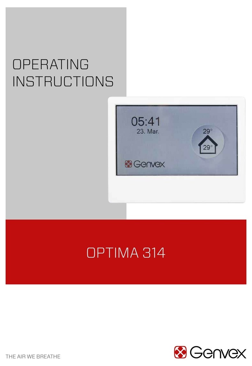
THK TSC Series User manual

INSTRUCTION MANUAL
THK Electrical Actuator Controller Series
Stepper Driver Controller
TSC
No.6120-2(0)E

iTSC
Table of Contents
1. Introduction
1-1
1-1 Acknowledgment 1-2
1-2 About this manual 1-2
1-3 How to use this product 1-3
1-4 About product support 1-3
1-5 About related instruction manuals 1-3
1-6 Product and company information 1-3
2. Safety precautions 1-4
2-1 About ranks of precautions 1-4
2-2 About description of precautions 1-4
2-3 Safety precautions 1-5
3. System configuration 1-6
3-1 System configuration diagram 1-6
4. Flow until using the product 1-7
1. Check products 2-2
1-1 Check the package contents of TSC 2-3
1-2 Options 2-5
1-3 Names of individual parts and functions 2-6
1-4 Store and dispose of products 2-7
2. How to install 2-8
2-1 Installation environment 2-8
2-2 Install TSC 2-9
1. How to wire 3-2
1-1 Entire wiring 3-3
1-2 Connect peripheral devices to power supply 3-4
1-3 Connect to PC 3-11
1-4 Connect to TDO 3-11
1-5 Peripheral devices 3-12
1. Introduction
1-1
2. Installation
2-1
3. Wiring
3-1

ii TSC
Table of Contents
2. External input and output (CN1) 3-13
2-1 Electrical specification 3-13
2-2 Signal name 3-15
2-3 Pin assignment 3-19
2-4 Optional I/O cable 3-25
1. Overview 4-3
1-1 Type of function mode 4-3
1-2 Selection by intended use 4-3
1-3 Timing chart (Common to position move) 4-4
2. Function modes 0, 2 and 3 4-5
2-1 Specify and execute STEP No. 4-5
2-2 How to specify STEP No. 4-5
2-3 How to obtain STEP No. whose operation has been completed 4-5
2-4 Timing chart 4-6
3. Function mode 1 4-7
3-1 Manual operation 4-7
3-2 Position instruction 4-7
3-3 Methods of position instruction 4-8
3-4 Specify and execute STEP No. 4-8
3-5 How to obtain STEP No. whose operation has been completed 4-8
3-6 Timing chart (Normal mode) 4-8
3-7 Timing chart (Instruction mode) 4-9
4. Function mode 4 4-10
4-1 Specify and execute STEP No. 4-10
4-2 Move command method 4-10
4-3 How to obtain STEP No. whose operation has been completed 4-11
4-4 Timing chart 4-11
5. Function mode 5 4-12
5-1 Specify and execute STEP No. 4-12
5-2 Move command method 4-12
5-3 Position detection signal 4-12
5-4 Timing chart 4-13
4. TSC functions
4-1
3. Wiring
3-1

iii TSC
Table of Contents
1. Operation mode 5-4
1-1 MANUAL mode 5-5
1-2 AUTO mode 5-5
1-3 MANUAL mode switching 5-5
2. Stop mode 5-6
2-1 Invalid 5-6
2-2 Auto servo OFF 1 (ASO 1) 5-6
2-3 Auto servo OFF 2 (ASO 2) 5-6
2-4 Auto servo OFF 3 (ASO 3) 5-6
2-5 Full servo control (SERVO) 5-7
3. Servo ON 5-8
3-1 Servo ON 5-8
4. Zero return 5-9
4-1 Zero return method 5-9
4-2 Positive/negative of moving direction 5-9
5. Pause 5-10
5-1 Pause 5-10
6. Manual operation 5-11
6-1 Manual operation 5-11
7. Positioning operation 5-12
7-1 Positioning operation 5-12
8. Pressing operation 5-13
8-1 Pressing operation 5-13
9. Torque determination 5-14
9-1 Torque determination 5-14
10. Area determination 5-15
10-1 Area determination 5-15
11. Speed switching 5-16
11-1 Speed switching 5-16
5. Operations and adjustment
5-1

iv TSC
Table of Contents
12. Brake release 5-17
12-1 Release with switch 5-17
12-2 Release with external input and output 5-17
13. General precautions 5-18
13-1 General precautions 5-18
14. Parameters 5-19
14-1 Parameter: Actuator information 5-19
14-2 Parameter: Actuator operation settings 5-19
14-3 Parameter: External interface 5-22
14-4 Parameter: Servo gain 5-23
5. Operations and adjustment
5-1
1. Alarm lists 6-2
1-1 Alarm lists 6-2
1-2 About the status of the servo when an alarm sounds 6-3
2. Alarm code 6-4
2-1 Alarm code 6-4
3. Causes and counter measures of alarms 6-5
3-1 Causes and counter measures of alarms 6-5
1. Maintenance and inspection 7-2
1-1 Standard of durability of consumables in the driver controller TSC 7-2
2. Product warranty 7-3
2-1 Free warranty period 7-3
2-2 Usage conditions (range) 7-3
2-3 Warranty scope 7-3
2-4 Exclusion of warranty liability 7-4
2-5 Delivery conditions 7-4
6. Troubleshooting
6-1
7. Maintenance and
Warranty
7-1
8. Technical
materials
8-1
1. Driver controller TSC 8-2
1-1 Specifications and dimensional drawing 8-2
2. Cables 8-3
2-1 Connection cable 8-3

1-1
1. Introduction
TSC
This section includes intro-
duction about the product
and this manual.
This section includes gen-
eral precautions to follow
when using the product.
Be sure to read this sec-
tion before use and ob-
serve the precautions.
This section includes intro-
duction about peripheral
devices to be used with
this product.
This section describes
installation and setting
processes to make this
product ready for use.
About this chapter
This chapter describes the overview of the product.
This chapter includes information that we want you to check and understand before working with the product.
1. Introduction ………………… 1-1
1-1. Acknowledgment…………………………… 1-2
1-2. About this manual ………………………… 1-2
1-3. How to use this product…………………… 1-3
1-4. About product support …………………… 1-3
1-5. About related instruction manuals ……… 1-3
1-6. Product and company information ……… 1-3
2. Safety precautions ………… 1-4
2-1. About ranks of precautions ……………… 1-4
2-2. About description of precautions ……… 1-4
2-3. Safety precautions ………………………… 1-5
3. System configuration ……… 1-6
3-1. System configuration diagram…………… 1-6
4. Flow until using the product 1-7

1. Introduction
1-2 TSC
1-1 Acknowledgment
Thank you for purchasing our product.
This product is designed and manufactured to be incorporated in devices with wide range of ap-
plication including conveyance system, implementing equipment, automated assemblers, and posi-
tioning equipment, etc.
We hope our creative inventions and unique technologies contribute to your further prosperity.
1-2 About this manual
1-2-1 Intended audience
The person in charge of designing embedded systems of the product and installing, wiring, and
maintaining the product, and the person who actually uses the product.
1-2-2 Purpose
This manual describes correct handling methods and precautions for the product.
For the maximum performance and long life of the product, carefully read and understand this man-
ual to safely and correctly use the product.
If you access our website or use the printed version of this manual, be sure to keep it in the place
that the intended audience can refer to it when needed.
1-2-3 Notice and attention
Do not use or handle the product in the ways that are not described in this manual.
Do not reproduce, reprint, or lend the whole contents or a part of this manual without permission.
Please note that description in this manual is subject to change without prior notice in the future,
due to improvements of the product or other reasons.
We have made all possible efforts to make the content of this manual accurate. However, if you
find any mistake or uncertainty in this manual, please contact our Customer Support (refer to
back cover).
Drawings show representative examples, and may differ from your product.
Note that THK shall not be liable for any result incurred by applying this manual, regardless of the
reason.
This manual can be applied to special types. However, the descriptions defined in the delivery
specification drawings or the delivery specification documents of those special types should take
precedence over this manual.
* Special types represent the products that have different materials and specifications from those
of the standard products on catalogs.
1-2-4 Notation of this manual
• Notes that can lead to unsatisfactory functions, error, or damage of the product if not observed while using
the product.
• Supplementary information for the description.
• Reference information for the description.
1.
Introduction
Important
Reference
Note

1. Introduction
1.
Introduction
1-3 TSC
1-3 How to use this product
This product cannot be used for the devices or systems that are used under the situations that
can affect human life.
If you consider using this product for special applications such as passenger movement vehicle,
medical, aerospace, nuclear power, and electric power devices or systems, be sure to consult
with THK in advance.
This product is manufactured under the strict quality control, however, that does not mean that
the product is free from failure. For applications to the equipment that may suffer serious acci-
dents or loss from the failure of this product, install safety devices or backup devices that prevent
such serious accidents or loss.
1-4 About product support
For the following information, please contact our Customer Support (refer to back cover).
Technical support for this product
1-5 About related instruction manuals
When you use the driver controller TSC, read the following instruction manuals as necessary.
・Controller series Setup tool D-STEP
・Controller series Digital operator TDO
1-6 Product and company information
To find the latest product and company information, we recommend you to periodically access our
website.
Website URL: http://www.thk.com/
Technical support website URL: https://tech.thk.com/
• For the driver controller TSC, select the electrical actuator to use when purchasing it. Use them in the
prescribed combination. ( →P.2-3)
Important

1-4
1. Introduction
TSC
2-1 About ranks of precautions
This manual uses the classifications of "Danger," "Warning," and "Caution" for warning indications
for safety matters.
2-2 About description of precautions
Precautions are classified as "Prohibition," "Instruction," and "Precaution" according to the action.
This mark indicates
"prohibition" of the
action.
This mark indicates
"instruction" for
the action.
This mark indicates
"caution" about
the action.
Prohibited Do not
disassemble
Obligatory Provide grounding
connection
Caution Caution –
Electrical shock
Caution –
Flammable
Caution – High
temperature
Caution –
Getting caught
DANGER Erroneous handling may urgently cause
death or serious injury to a person
WARNING Erroneous handling may cause death or
serious injury to a person
Erroneous handling may cause injury to a
person or property damage only
CAUTION
2.
Safety precautions

1-5
1. Introduction
2.
Safety precautions
TSC
2-3 Safety precautions
While the actuator is operating or
operable, do not enter the working
area of any moving part including
the load.
Doing so may cause you to touch the
moving part and get injured.
If the product fails or any abnor-
mality is observed, shut down the
power of the driver controller TSC.
Such abnormality may cause a mal-
function of actuator, resulting in dam-
age or injury.
Do not touch the internal part of
the driver controller TSC.
Doing so may cause electric shocks.
Do not damage, tuck, or apply ex-
cessive stresses on the cable.
Doing so may cause electric shocks.
Do not modify, disassemble, or al-
ter the product.
Doing so may cause injury or fault.
During the operation, or for a while
after turning the power off, do not
touch the driver controller TSC,
motor or motor cover because
they should be hot.
Doing so may cause burns.
Prohibited
Obligatory
Caution -
Electrical shock
Do not
disassemble
Caution – High
temperature
Do not impact the product and
do avoid rough handling such as
throwing it.
Doing so may cause the fault or dam-
age that leads to injury.
Do not frequently switch the power
between on and off.
Doing so may generate heat from the
internal parts of the driver controller
TSC, which results in fault or burns.
Do not set the speed or accelera-
tion setting or place the load on the
actuator that exceed the actuator
specification.
Doing so may cause motor failure,
which leads to unexpected accidents
or damages.
If an alarm is generated, remove
the cause, check the safety, de-
activate the alarm, and restart the
operation. ( →P.6-5)
Failure to do so may result in failure,
which leads to injury.
Use this product with a combina-
tion that is specified beforehand.
Failure to do so may cause fire or fault.
Observe the specified input volt-
age.
Failure to do so may cause fire or fault.
Prohibited
Obligatory
Caution –
Flammable
WARNING
CAUTION

1-6
1. Introduction
TSC
3-1 System configuration diagram
The diagram below shows a representative example for using the economy series ES with the
driver controller TSC.
Cables used for connecting the devices shown with ★should be prepared by yourself.
3.
System configuration
TDO(→*1) PC (D-STEP) (→*2)
Higher device
Emergency stop switch
(This should be pre-
pared by yourself. )
(→P.3-12)
Driver controller
TSC
The actuator cable is provided
with the actuator unit.
(→*3)
* To use a 10m actuator cable,
please insert a noise filter.
Recommended noise filter is
“RSAN-2003 (made by TDK-
Lambda Corporation)”.
24V DC power
★
★
★Power supply should be pre-
pared by yourself. Power con-
nector is provided with TSC.
(→P.3-4)
CN1
CN2
CN4
CN3
CN5
Actuator
PC communication
cables are provid-
ed as an option.
(→P.2-5)
★
I/O connector for CN1 is
provided with TSC.
I/O cables are provided
as an option.
(→P.2-5)
★
*1: See the separate TDO Instruction Manual.
*2: See the separate D-STEP instruction manual.
*3: See the separate ES/EC instruction manual.

1-7
1. Introduction
TSC
1. Safety check
①Safety statement check →P.1-4
②Safety check of the installation location
→P.2-8
③Installation check →P.2-9 to 2-11
2. Preparation ①Preparation of required devices →P.1-6
②Package contents check →P.2-3 to 2-4
3. Installation ①Installation environment check →P.2-8
②Installation →P.2-9 to 2-11
4. Wiring
①Connection between each device and
cable →P.3-2 to 3-25
5. Trial run and
adjustment
①Preparation of setup tool D-STEP
(see the separate Instruction Manual of
D-STEP)
②Trial run →P.5-4 to 5-18
③Parameter setting →P.5-19 to 5-23
6. Setup tool setting
①Setup tool setting
(see the separate Instruction Manual of
D-STEP)
4.
Flow until using the product

2-1
2. Installation
TSC
1. Check products ……………… 2-2
1-1. Check the package contents of TSC …… 2-3
1-2. Options ……………………………………… 2-5
1-3. Names of individual parts
and functions ……………………………… 2-6
1-4. Store and dispose of products…………… 2-7
2. How to install ………………… 2-8
2-1. Installation environment ………………… 2-8
2-2. Install TSC …………………………………… 2-9
This section describes the
installation procedures of
this product.
About this chapter
This chapter describes how to check the package contents and to install it to the machine and facilities.
This section is primarily intended for those in charge of installation of this product to a machine and facilities.
This section describes the
precautions on use of this
product.

2. Installation
2-2 TSC
Do not stand on the packaging box
or this product.
Doing so may cause malfunction or
damage that leads to injury.
When carrying the product, do not
hold the cable.
Doing so may cause damage of the
cable that leads to injury.
Prohibited
When any abnormality is detected
on the product, do not continue to
use it.
Using a fractured product may cause
malfunction that leads to injury or fault.
When you find any failures, please con-
tact our Customer Support ( ⇨refer to
the back cover).
Prohibited
CAUTION
1.
Check products
WARNING
For the combination of the driver
controller TSC and actuator, do not
use actuators with models other
than TSC.
Doing so may cause unexpected mo-
tions, accidents or failures.
Prohibited
Actuator model: ES4-06-0300B-TS/35PL-D00-S3
Driver controller model: TSC-015B-MOD-ES4-06-D
Example of combination

2. Installation
1.
Check products
2-3 TSC
1-1 Check the package contents of TSC
1-1-1 Check the model/type of the product
Check the model indicated on the product label against the purchase information.
TSC -015 -B-MOD -ES6 -06 -D-B
①Model TSC: Driver controller TSC
②Current value 015 : 1.5 A
③Design symbol B
④Type MOD : Mode switching type
⑤Applicable actuator ES3, ES4, ES5, ES6
ES3R, ES4R, ES5R, ES6R
EC3, EC4 (Select "EC3" for EC3H, and "EC4" for EC4H. )
EC3R, EC4R
KRF4, KRF5, CKRF4, CKRF5
⑥Applicable actuator
Ball screw lead
06 : 6 mm
10 : 10 mm
12 : 12 mm
⑦Zero point D : Motor side
R : Reverse motor side
⑧Brake No symbol : No brake
B : With brake
Note) Refer to the respective actuator catalogs for the model configuration of driver controller TSC
for ET and EG.
Model number
(See the following)
Serial number
⑦ ⑧⑥⑤④③②①

2. Installation
1.
Check products
2-4 TSC
1-1-2 Checking the type and number of accessories
No cable is provided, so please separately prepare a cable.
1-1-3 Check the product for any damage or abnormality
After the checking, keep the product packed in the packaging box until the start of installation work.
Type of parts Model number Qty.
Driver controller * See the product label 1
Power connector
Current product Conventional product
1
FK-MCP 1,5/7-ST-3,81
(PHOENIX CONTACT)
MPC300-38107
(DECA)
I/O connector
Current product Conventional product
1
Plug
HD-44SP
(MISUMI)
Plug
DBH44MCA
(NSXD)
Cover
RDA-25H-UNC
(MISUMI)
Cover
DT44PB
(NSXD)
1
• For any special type, check against the delivery specification documents.
Reference

2. Installation
1.
Check products
2-5 TSC
1-2 Options
1-2-1 D-STEP
Driver controller
TSC side (CN3)
PC side
USB
A setup tool. This can be downloaded from our website free of charge.
* Registration with the technical support is required to download.
URL: https://tech.thk.com/
In addition, a PC communication cable is required to use D-STEP.
For details, see the separate D-STEP Instruction Manual.
1-2-2 TDO
The digital operator for driver controller TSC, TLC and THC.
Model: TDO-N
For details, see the separate TDO Instruction Manual.
1-2-3 I/O cable
A cable with a soldered I/O connector for external input and output signals (CN1).
Model: CBL-TSC-IO-□□ (03: 3 m, 05: 5 m, 10: 10 m)
For details, see (→P.3-14) (→P.3-25)
(Cable length)
A PC communication cable for use with D-STEP.
Model: CBL-COM-03
For details, see the separate D-STEP Instruction Manual.
1-2-4 PC communication cable
□□
Driver controller side Host controller side
Driver controller side PC side

2. Installation
1.
Check products
2-6 TSC
1-3 Names of individual parts and functions
1-3-1 Driver controller TSC
Connectors for CN1 and CN5 are provided with this product. No cable is provided, so please
separately prepare it. For CN1, an optional package with a cable is available. (→P.2-5) (→P.3-25)
A cable to connect to CN3 and PC is available as an option. (→P.2-5)
PWR
When energized, it lights in red.
CN2
Actuator's encoder connector is
connected.
CN4
Actuator's motor connector is
connected.
ID
The ID (identification) number is
selected.
CN3
Communication cable for PC and
TDO is connected.
CN5
Power supply and emergency stop
SW are connected.
SV/ALM
It lights in green when the servo
is turned ON. In the alarm state, it
lights in red.
BRK OFF
When the brake is turned OFF
(released), it lights in yellow.
MOT
When the motor is turned ON, it
lights in red.
CN1
External input and output signals
are connected.
(FG)
Ground wire is connected.
BRK OFF/MANU/AUTO
The brake is turned ON/OFF and
the mode is switched.

2. Installation
1.
Check products
2-7 TSC
1-4 Store and dispose of products
1-4-1 For storage
If the product is not used for a while, put the product with packing materials in a packaging box for
transportation and store it in the following place:
Indoor or outdoor at the driver controller TSC's ambient temperature of -20 to 85°C (no freezing)
Indoor or outdoor at the driver controller TSC's ambient humidity of 90% RH or less (no conden-
sation)
Stored with the power disconnected
Place where no direct sunlight nor radiation heat reaches
Place where the product is not exposed to water
Place where no flammable substance exists in the vicinity
Place where no strong electric field nor strong magnetic field develops
Place where a vibration or shock does not transmit to the product
Place where liquid containing impurities such as conductive iron dust, powder such as solid
abrasive, dust, oil mist, cutting oil, water content, salt content, organic solvent, or corrosive/flam-
mable gas is not generated or does not float
1-4-2 For disposal
Disposal of the product should be consigned to a certified industrial-waste disposer.
Do not put the product into fire to dispose of it.
Doing so may lead the product to burst, generate noxious gas, or cause injury due to bursting.
Do not dispose of the product by yourself.
Be sure to consign disposal of the product as an industrial waste to a certified industrial-waste
disposer.
WARNING

2-8
2. Installation
TSC
2-1 Installation environment
Do not put the product into fire to dispose of it.
Doing so may lead the product to burst, generate noxious gas, or cause injury due to bursting.
2-1-1 Installation environment of the driver controller TSC
Place it within a control panel that meets the following conditions:
Indoor or outdoor at the ambient temperature of 0 to 40 °C (no freezing)
Indoor or outdoor at the ambient humidity of 90% RH or less (no condensation)
Place at an altitude below 1000 m
Place where the product is not exposed to water
Place where no flammable substance exists in the vicinity
Place where a vibration or shock does not transmit to the product
Place where liquid containing impurities such as conductive iron dust, powder such as solid
abrasive, dust, oil mist, cutting oil, water content, salt content, organic solvent, or corrosive/flam-
mable gas is not generated or does not float
2-1-2 Water drop-, oil drop- and dust-proof
This product does not have a water drop-, oil drop- and dust-proof structure. If the product is to be
used in an environment where it is exposed to water content, oil content, powder or dust, take ap-
propriate measures before using it.
Failure to do so may cause injury, fault or fracture.
In addition, please take note that we take no responsibility for any negative effect of using the prod-
uct without appropriate measures.
Caution –
Flammable
WARNING
2.
How to install
This manual suits for next models
1
Table of contents
Other THK Controllers manuals
