THK Economy Series User manual

ACTUATOR
UNITS
ES/EC
CATALOG No.373-9E-EU
Economy series
NEW
For details, visit THK at www.thk.com
∗Product information is updated regularly on the THK website.

ELECTRIC ACTUATOR
1
Economy series
Lightweight, Compact
Features
Electrical Actuator
Economy series
ES/EC
Cylinder Type
EC
Slider Type
ES Table
Table cover
Housing A
Strip seal
Grease lid
Base
Rod
Housing B
Side cover
Housing-B cover
When GR is selected: gray
Housing A
By incorporating an LM Guide within its rectilinear guide, the ES provides both compactness and reliability.
Compact and reliable
The use of LM Guides reduces the number of components required, making the ES available at a reasonable cost.
Reasonably priced
The ES incorporates the model SRS LM Guide, equipped with ball retainers, as well as Lubricator QZ, for optimal
ball-screw lubrication. The combined effect provides for long-term maintenance-free operation.
Long-term maintenance-free operation
The service life of the LM Guide and ball screw can be calculated based on usage conditions.
Contact THK for details.
Predictable service life

ELECTRIC ACTUATOR
2
Economy series
Change the cover color to gray
You can change the color of ES housing cover to
gray.
No symbol: red
When GR is selected: gray
If the GR is not included in the model
configuration, cover will be red.
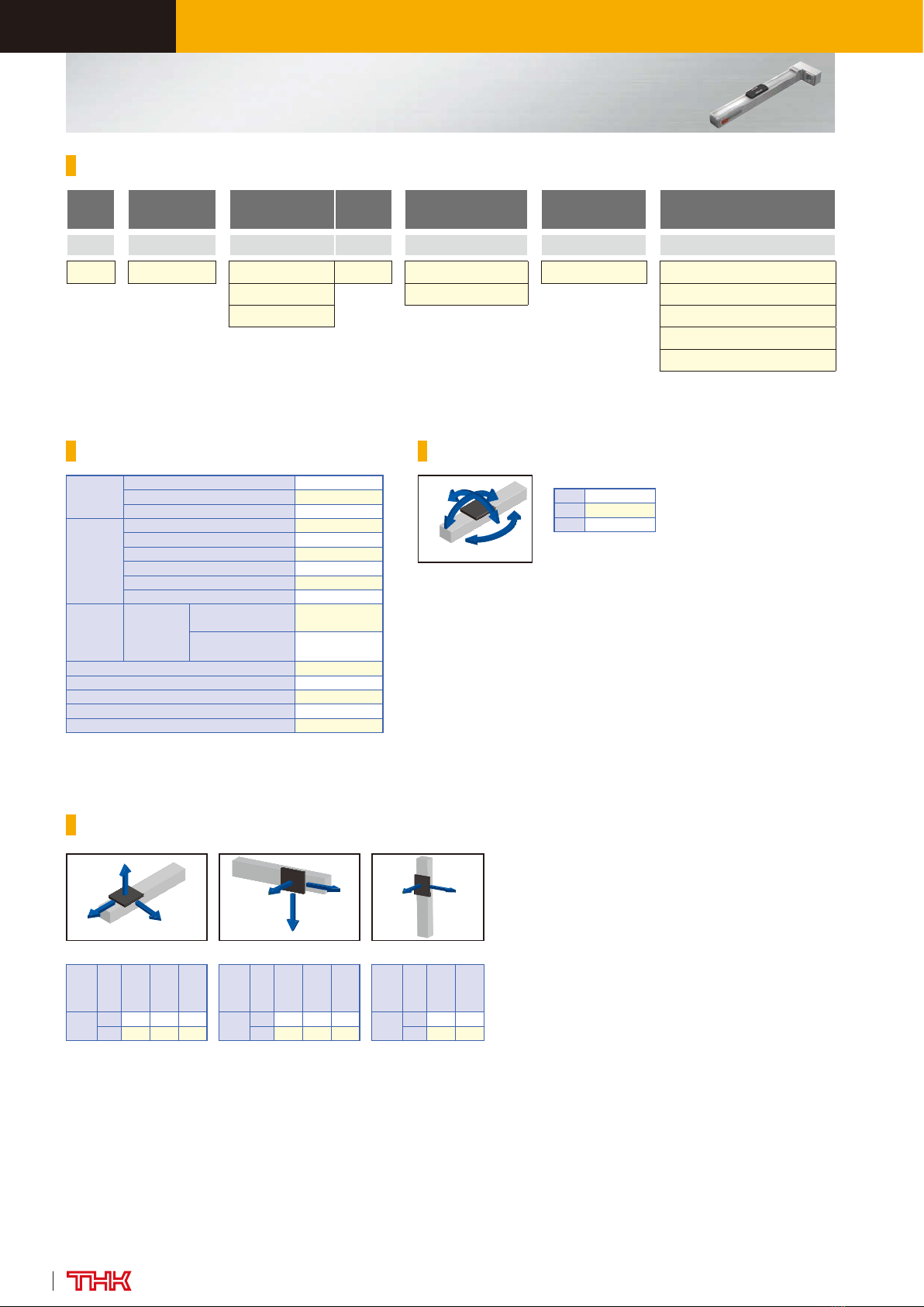
ES/EC (without motor)
Model Ball screw
lead Stroke Design
symbol
With/without
motor
Intermediate
flange Option
ES4R
-
06
-
0150 B
-
0
-
A
-
MR−GR−FL−LB
(1) (2) (3) (4) (5) (6) (7)
ES3 06: 6mm
0050
:
50mm B
0: Without motor N: None No symbol: ES : Red cover
ES4 12: 12mm
0100
:
100mm
1: With motor
(Prepared by THK)
A: EC : None
ES5
0150
:
150mm
B
MR
:
Motor right wrap
×1
ES6
0200
:
200mm
C
ML
:
Motor left wrap
×
1
ES3R
0250
:
250mm
GR:
Change the cover color to gray
ES4R
0300
:
300mm
SB: With slider base
×
2
ES5R
0350
:
350mm
CB: With cylinder base
×
3
ES6R
0400
:
400mm
FL: With flange
×
3
×
4
EC3
0450
:
450mm
LB: With link ball
×
3
×
4
EC4
0500
:
500mm
£1£2: Sensor
×
2
EC3R
0550
:
550mm
EC4R
0600
:
600mm
EC3H
EC4H
/
Option symbol ML: Motor left wrap Option symbol MR: Motor right wrap
R represents motor
wrap, and H
represents with
linear bush.
When 0 is selected, a coupling is not provided
for motor direct coupled specification. Timing
pulley and timing belt are provided for motor
wrap configuration. When 1 is selected, THK
will prepare a motor and install it.
For ES3, ES3R, EC3, EC3R and
EC3H, have ball screw lead of
6mm only.
Maximum stroke
differs depending on
models.
ES3: 300mm
ES4: 400mm
ES5: 500mm
ES6: 600mm
EC3: 200mm
EC4: 300mm
Specify the option symbol by
writing in the order of
description from left adding "−".
×1 Valid only when ES£R or EC£R
is selected in model (1).
×2 Valid only when ES is selected in
model (1).
×3 Valid only when EC is selected in
model (1).
×4 If you select EC£H for model (1),
FL and LB cannot be selected.
Slider type ES Cylinder type EC
(6) Intermediate flange P. 33
(7) Options
GR: Change the cover color to gray
P. 33
SB: With slider base P. 34
CB: With cylinder base P. 38
FL: With flange P. 38
LB: With link ball
P. 38
£1£2: Sensor P. 36
Pages for detailed
description
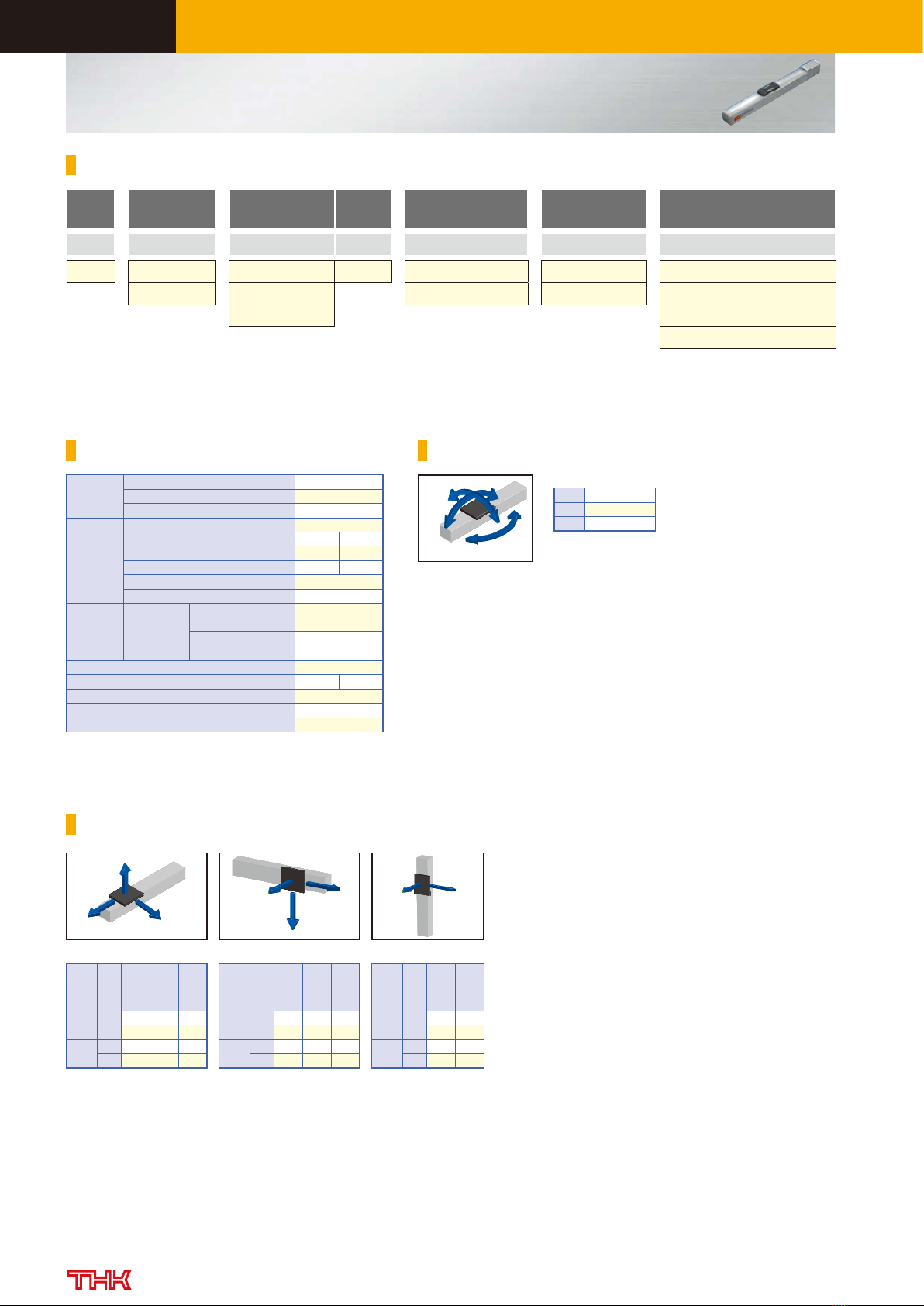
Motor wrap direction
Model Conguration
Page 06: Folded direction for EC
Option symbol ML: Motor left wrap Option symbol MR: Motor right wrap

ELECTRIC ACTUATOR
3
Economy series
Lineup List
Model Ball screw lead
[mm]
Stroke
[mm]
Rated speed
×
1
[mm/s]
The reference motor Maximum load capacity
×
1[kg]
Maximum speed for each stroke
×
3[mm/s]
Stroke [mm]
Stepper motor Servo motor [W]
Horizontal mount
Vertical mount 50 100 150 200 250 300 350 400 450 500 550 600
ES3 6 50 to 300 — £28 — 1 0.5 300
ES4
6
50 to 400 — £35 —
to 9 to 4 300
12 to 7.5 to 1.5 600
ES5
6
50 to 500
300
— 50
10 5 300
12 600 6 2 600
ES6
6
50 to 600
300
— 50
10 5 300 270 230
12 600 6 2 600 540 460
ES3R 6 50 to 300 — £28 — 1 to 0.5 300
ES4R
6
50 to 400 — £35 —
4 to 1.5 300
12 2 1 600
ES5R
6
50 to 500
300
— 50
8 2 300
12 600 6 1 600
ES6R
6
50 to 600
300
— 50
8 2 300 270 230
12 600 6 1 600 540 460
EC3 6 50 to 200 — £35 — 15 6 300 250
EC4
6
50 to 300
300
— 50
14 6 300 230 170
12 600 7 3 600 460 340
EC3R 6 50 to 200 — £35 — 15 3 300 250
EC4R
6
50 to 300
300
— 50
14 6 300 230 170
12 600 7 3 600 460 340
EC3H 6 50 to 200 — £35 — 15 6 300 250
EC4H
6
50 to 300
300
— 50
14 6 300 230 170
12 600 7 3 600 460 340
×
1Based on rated motor speed (3,000min-1).
×
2Load mass represents values with THK control devices used. Determine load mass according to specications of the motor you
actually use. For selecting a motor, see Reference Materials for Selecting on page 39 and 40.
×
3Maximum speed is dependent on motor speed of 3,000min-1 and, if applicable, permissible rotation speed of ball screw.

ELECTRIC ACTUATOR
4
Economy series
Model Ball screw lead
[mm]
Stroke
[mm]
Rated speed
×
1
[mm/s]
The reference motor Maximum load capacity
×
1[kg]
Maximum speed for each stroke
×
3[mm/s]
Stroke [mm]
Stepper motor Servo motor [W]
Horizontal mount
Vertical mount 50 100 150 200 250 300 350 400 450 500 550 600
ES3 6 50 to 300 — £28 — 1 0.5 300
ES4
6
50 to 400 — £35 —
to 9 to 4 300
12 to 7.5 to 1.5 600
ES5
6
50 to 500
300
— 50
10 5 300
12 600 6 2 600
ES6
6
50 to 600
300
— 50
10 5 300 270 230
12 600 6 2 600 540 460
ES3R 6 50 to 300 — £28 — 1 to 0.5 300
ES4R
6
50 to 400 — £35 —
4 to 1.5 300
12 2 1 600
ES5R
6
50 to 500
300
— 50
8 2 300
12 600 6 1 600
ES6R
6
50 to 600
300
— 50
8 2 300 270 230
12 600 6 1 600 540 460
EC3 6 50 to 200 — £35 — 15 6 300 250
EC4
6
50 to 300
300
— 50
14 6 300 230 170
12 600 7 3 600 460 340
EC3R 6 50 to 200 — £35 — 15 3 300 250
EC4R
6
50 to 300
300
— 50
14 6 300 230 170
12 600 7 3 600 460 340
EC3H 6 50 to 200 — £35 — 15 6 300 250
EC4H
6
50 to 300
300
— 50
14 6 300 230 170
12 600 7 3 600 460 340

ELECTRIC ACTUATOR
5
Economy series
ES3 Slider type Directly coupled without motor
Model Ball screw lead Stroke Design
symbol With/without motor Intermediate
ange Option
ES3 –06 –0150 B –0–A–GR–SB
ES3 06: 6mm 0050: 50mm B 0: Without motor ANo symbol: Red cover
to 1: With motor B GR:
Change the cover color to gray
0300: 300mm SB: With slider base
£1£2: Sensor
Model Conguration
Basic Specications
Reference Permissible Overhang Length ×1 ×2
×
1Distance from the center of the top face of the table to the load center of gravity
under the following conditions: 5,000km running life, single-direction load, 0.3G
horizontal or vertical, 150mm stroke.
×
2Value when THK control device is used. Actual load mass should be determined
based on the specifications of the motor used. See "Reference Materials for Selecting
ES" in P.39.
Ball
screw
lead
[mm]
Load
mass
[kg]
A B C
60.5 200 200 200
1 200 160 200
Horizontal mount [mm]
Ball
screw
lead
[mm]
Load
mass
[kg]
A B C
60.5 200 200 200
1 170 150 200
Wall mount [mm]
Ball
screw
lead
[mm]
Load
mass
[kg]
A C
60.3 200 200
0.5 200 200
Vertical mount [mm]
C
B
A
Horizontal use
AB
CWall use
AC
Vertical use
LM Guide
(SRS9)
Basic dynamic load rating C [N] 2690
Basic static load rating C0[N] 2310
Radial clearance [mm] −2 to +2
Ball screw
portion
Shaft diameter [mm] f6
Lead [mm] 6
Basic dynamic load rating Ca [N] 1400
Basic static load rating C0a [N] 2440
Root diameter [mm] f5.1
Ball center-to-center diameter [mm] f6.3
Bearing
portion
(xed side)
Axial direction
Basic dynamic load
rating Ca [N] 6550
Static permissible load
P0a [N] 2310
Permissible rotational speed [min-1] 3000
Starting torque [N·mm] 8
Positioning repeatability [mm]
×
2±0.020
Lost motion [mm]
×
20.1
Maximum input torque [N·m] 0.065
MA6.0
MB7.5
MC5.9
[N·m]
M
M
MC
B
A
Static Permissible Moment ×1
×
1Static maximum permissible moment when unit is stationary. Moment standards: MAand MC: top of table; MB: center of table.
×
2When the appropriate motor is used.

ELECTRIC ACTUATOR
6
Economy series
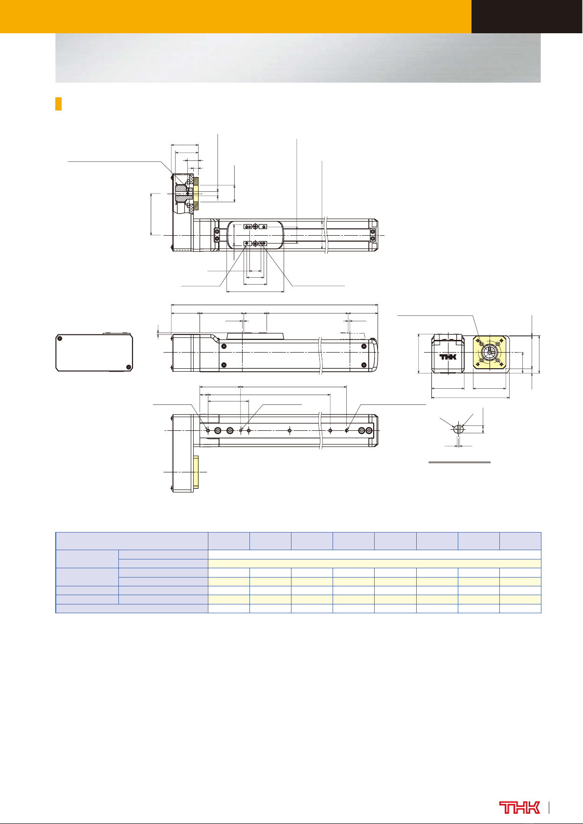
Dimensions
×
1Load capacity and maximum speed vary depending on the motor used.
×
2Dependent on the permissible rotational speed of the ball screw.
Stroke [mm]
(Stroke between mechanical stoppers) 50
(56)100
(106)150
(156)200
(206)250
(256)300
(306)
Maximum speed
×1 ×2
[mm/s]
Ball screw lead: 6mm 300
Dimensions [mm]L 209.2 259.2 309.2 359.2 409.2 459.2
L185 135 185 235 285 335
Mounting pitch count N 2 3 4 5 6 7
Mounting hole count n 3 4 5 6 7 8
Weight [kg] 0.65 0.7 0.8 0.85 0.9 0.95
×1Stroke up to mechanical stopper.
×2indicates an opening.
Intermediate flange symbol BIntermediate flange symbol A
(PCD28, from the back surface)
A
Arrow A view
11±0.02
17
(66.4)
(28)
(Table cover width)
17±0.02
(Tolerance is applicable to φ2)
48
23 Nx50
50 φ2H7 Depth 4
2 +0.03
0
n-M3 depth 4.5
21.4
21.4
0.50.5
R1
R1
L1
Elongated hole depth 2
1
21.4(37.5)
32
40
2-φ2H7 Depth 5
4-M3 depth 5
(3)1
Stroke
(3)1
φ22H7 (Intermediate flange symbol B)
φ20H7 (Intermediate flange symbol A)
φ6h7
φ20
24.6
φ15
2.5 (Intermediate flange symbol B)
3 (Intermediate flange symbol A)
10
23
23
45°
22.5
39
22.5
39
(L)
49 (51.3)
8
(34)
2
(From the back surface)
(See drawing below)
B
φ6h7
0.5
7.5
Detailed Diagram: Section B
4-3.4 drill through
φ6 counter bore depth 3.3
4-2.9 drill through
φ5.5 counter bore depth 2.8
Elongated hole (detail)
ES3
ELECTRIC ACTUATOR
7
Economy series
ES3R Slider type Motor wrap
Model Ball screw lead Stroke Design
symbol With/without motor Intermediate
ange Option
ES3R –06 –0150 B –0–A–MR–GR
ES3R 06: 6mm 0050: 50mm B 0: Without motor A MR: Motor right wrap
to 1: With motor ML: Motor left wrap
0300: 300mm GR:
Change the cover color to gray
SB: With slider base
£1£2: Sensor
Model Conguration
Basic Specications
Reference Permissible Overhang Length ×1 ×2
×1Distance from the center of the top face of the table to the load center of gravity
under the following conditions: 5,000km running life, single-direction load, 0.3G
horizontal or vertical, 150mm stroke.
×2Value when THK control device is used. Actual load mass should be determined
based on the specifications of the motor used. See "Reference Materials for Selecting
ES" in P.39.
Ball
screw
lead
[mm]
Load
mass
[kg]
A B C
60.5 200 200 200
1 200 160 200
Horizontal mount [mm]
Ball
screw
lead
[mm]
Load
mass
[kg]
A B C
60.5 200 200 200
1 170 150 200
Wall mount [mm]
Ball
screw
lead
[mm]
Load
mass
[kg]
A C
60.3 200 200
0.5 200 200
Vertical mount [mm]
C
B
A
Horizontal use
AB
CWall use
AC
Vertical use
LM Guide
(SRS9)
Basic dynamic load rating C [N] 2690
Basic static load rating C0[N] 2310
Radial clearance [mm] −2 to +2
Ball screw
portion
Shaft diameter [mm] f6
Lead [mm] 6
Basic dynamic load rating Ca [N] 1400
Basic static load rating C0a [N] 2440
Root diameter [mm] f5.1
Ball center-to-center diameter [mm] f6.3
Bearing
portion
(xed side)
Axial direction
Basic dynamic load
rating Ca [N] 6550
Static permissible load
P0a [N] 2310
Permissible rotational speed [min-1] 3000
Starting torque ×1[N·mm] 8
Positioning repeatability [mm] ×3±0.020
Lost motion [mm] ×30.1
Maximum input torque [N·m] 0.065
MA6.0
MB7.5
MC5.9
[N·m]
M
M
MC
B
A
Static Permissible Moment ×2
×1Pulley and timing belt not included.
×2Static maximum permissible moment when unit is stationary. Moment standards: MAand MC: top of table; MB: center of table.
×3When the appropriate motor is used.
Note: If the GR is not included in the
model configuration, cover will
be red.

ELECTRIC ACTUATOR
8
Economy series
Dimensions
×1Load capacity and maximum speed vary depending on the motor used.
×2Dependent on the permissible rotational speed of the ball screw.
Stroke [mm]
(Stroke between mechanical stoppers) 50
(56)100
(106)150
(156)200
(206)250
(256)300
(306)
Maximum speed
×1×2
[mm/s]
Ball screw lead: 6mm 300
Dimensions [mm]L 195.4 245.4 295.4 345.4 395.4 445.4
L185 135 185 235 285 335
Mounting pitch count N 2 3 4 5 6 7
Mounting hole count n 3 4 5 6 7 8
Weight [kg] 0.65 0.7 0.8 0.85 0.9 0.95
×1This is a stroke between mechanical stoppers.
×2indicates an opening.
2
48
50
0.50.5
23
17
(66.4)
21.4 (37.5)
(28)
(Table cover width)
Nx50
n-M3 depth 4.5
L1
21.4
21.4
1
R1
R1
Elongated hole depth 2
Stroke
4-M3 depth 5
(3)1
(3)1
(L)
(35.2) (51.3)
6
(12.7)
(28)
(33.2)
(45)
11±0.02
2-φ2H7 Depth 5
17 ±0.02
2+0.03
0
φ2H7 Depth 4
2-M3 (Hexagon socket set screw)
(90° equipartition)
(Distance between shafts)
(Tolerance is applicable to φ2)
(See drawing below)
φ5
(Pulley internal diameter)
φ20.5
2-3.4 through
φ
6 counter bore depth 3.4
(PCD28, from the back surface)
32
40
81
39
22
(1)
32
32
(6)
Elongated hole (detail)
ES3R
ELECTRIC ACTUATOR
9
Economy series
ES4
Slider type Directly coupled without motor
Model Conguration
Basic Specications
Reference Permissible Overhang Length ×1 ×2
×1Distance from the center of the top face of the table to the load center of gravity
under the following conditions: 5,000km running life, single-direction load, 0.3G
horizontal or vertical, 150mm stroke.
×2Value when THK control device is used. Actual load mass should be determined
based on the specifications of the motor used. See "Reference Materials for Selecting
ES" in P.39.
Ball
screw
lead
[mm]
Load
mass
[kg]
A B C
6 4.5 300 50 100
9 160 20 40
12 3.8 260 60 100
7.5 110 20 40
Horizontal mount [mm]
Ball
screw
lead
[mm]
Load
mass
[kg]
A B C
6 4.5 60 30 300
9 10 5 70
12 3.8 70 40 220
7.5 10 10 50
Wall mount [mm]
Ball
screw
lead
[mm]
Load
mass
[kg]
A C
6 2 100 110
4 30 40
12 0.8 260 300
1.5 130 150
Vertical mount [mm]
C
B
A
Horizontal use
AB
CWall use
AC
Vertical use
Model Ball screw lead Stroke Design
symbol With/without motor Intermediate
ange Option
ES4 –06 –0150 B –0–A–GR–SB
ES4 06: 6mm 0050: 50mm B 0: Without motor ANo symbol: Red cover
12: 12mm to 1: With motor B GR:
Change the cover color to gray
0400: 400mm SB: With slider base
£1£2: Sensor
LM Guide
(SRS9W)
Basic dynamic load rating C [N] 3290
Basic static load rating C0[N] 3340
Radial clearance [mm] −2 to +2
Ball screw
portion
Shaft diameter [mm] f8
Lead [mm] 6 12
Basic dynamic load rating Ca [N] 1770 920
Basic static load rating C0a [N] 3040 1600
Root diameter [mm] f6.8
Ball center-to-center diameter [mm] f8.4
Bearing
portion
(xed side)
Axial direction
Basic dynamic load
rating Ca [N] 8000
Static permissible load
P0a [N] 3240
Permissible rotational speed [min-1] 3000
Starting torque [N·mm] 12 21
Positioning repeatability [mm]
×
2±0.020
Lost motion [mm]
×
20.1
Maximum input torque [N·m] 0.16
MA9.3
MB13.5
MC17.7
[N·m]
M
M
MC
B
A
Static Permissible Moment ×1
×1Static maximum permissible moment when unit is stationary. Moment standards: MAand MC: top of table; MB: center of table.
×2When the appropriate motor is used.
Note: If the GR is not included in the
model configuration, cover will
be red.

ELECTRIC ACTUATOR
10
Economy series
Dimensions
Stroke [mm]
(Stroke between mechanical stoppers) 50 ( 54)100 ( 104)150 ( 154)200 ( 204)250 ( 254)300 ( 304)350 ( 354)400 ( 404)
Maximum speed ×1 ×2
[mm/s]
Ball screw lead: 6mm 300
Ball screw lead: 12mm 600
Dimensions [mm]L 220 270 320 370 420 470 520 570
L180 130 180 230 280 330 380 430
Mounting pitch count N 2 3 4 5 6 7 8 9
Mounting hole count n 3 4 5 6 7 8 9 10
Weight [kg] 1.2 1.3 1.4 1.5 1.6 1.7 1.8 1.9
×1Load capacity and maximum speed vary depending on the motor used.
×2Dependent on the permissible rotational speed of the ball screw.
×Stroke up to mechanical stopper.
50
10
50 φ3H7 Depth 5
n-M4 depth 6
L1
14 ±0.02
21
(70)
(34)
(Table cover width)
28
Nx50
20±0.02
(Tolerance is applicable to φ2.5)
28
26
3 +0.03
0
0.50.5
R1.5
R1.5
Elongated hole depth 3
2
40
48
2-φ2.5H7 Depth 6
4-M3 depth 6
(2)
(2)
Stroke (36.5)
(54)
(PCD28, from the back surface)
(From the back surface)
29
29
φ6h7
φ22H7 (Intermediate flange symbol B)
φ20H7 (Intermediate flange symbol A)
φ15
26.5 11
(42)
25.5
46
25.5
46
45°
6.5
51.5
(L)
Intermediate flange symbol A Intermediate flange symbol B
A
Arrow A view
φ20
B
Detailed Diagram: Section B
φ6h7
0.5
9
4-3.4 drill through
φ6 counter bore depth 3.3
4-3.4 drill through
φ6.5 counter bore depth 3.3
(See drawing below)
2.5 (Intermediate flange symbol B)
3 (Intermediate flange symbol A)
Elongated hole (detail)
ES4

ELECTRIC ACTUATOR
11
Economy series
ES4R Slider type Motor wrap
Model Conguration
Basic Specications
Reference Permissible Overhang Length ×1 ×2
×1Distance from the center of the top face of the table to the load center of gravity
under the following conditions: 5,000km running life, single-direction load, 0.3G
horizontal or vertical, 150mm stroke.
×2Value when THK control device is used. Actual load mass should be determined
based on the specifications of the motor used. See "Reference Materials for Selecting
ES" in P.39.
Ball
screw
lead
[mm]
Load
mass
[kg]
A B C
6 2 300 120 240
4 300 50 110
12 1 300 240 300
2 300 120 200
Horizontal mount [mm]
Ball
screw
lead
[mm]
Load
mass
[kg]
A B C
6 2 210 110 300
4 80 40 300
12 1 300 260 300
2 170 110 300
Wall mount [mm]
Ball
screw
lead
[mm]
Load
mass
[kg]
A C
6 0.8 280 300
1.5 140 160
12 0.5 300 300
1 210 240
Vertical mount [mm]
C
B
A
Horizontal use
AB
CWall use
AC
Vertical use
Model Ball screw lead Stroke Design
symbol With/without motor Intermediate
ange Option
ES4R –06 –0150 B –0–A–MR–GR
ES4R 06: 6mm 0050: 50mm B 0: Without motor A MR: Motor right wrap
12: 12mm to 1: With motor ML: Motor left wrap
0400: 400mm GR:
Change the cover color to gray
SB: With slider base
£1£2: Sensor
LM Guide
(SRS9W)
Basic dynamic load rating C [N] 3290
Basic static load rating C0[N] 3340
Radial clearance [mm] −2 to +2
Ball screw
portion
Shaft diameter [mm] f8
Lead [mm] 6 12
Basic dynamic load rating Ca [N] 1770 920
Basic static load rating C0a [N] 3040 1600
Root diameter [mm] f6.8
Ball center-to-center diameter [mm] f8.4
Bearing
portion
(xed side)
Axial direction
Basic dynamic load
rating Ca [N] 8000
Static permissible load
P0a [N] 3240
Permissible rotational speed [min-1] 3000
Starting torque ×1[N·mm] 12 21
Positioning repeatability [mm] ×3±0.020
Lost motion [mm] ×30.1
Maximum input torque [N·m] 0.16
MA9.3
MB13.5
MC17.7
[N·m]
M
M
MC
B
A
Static Permissible Moment ×2
×1Pulley and timing belt not included.
×2Static maximum permissible moment when unit is stationary. Moment standards: MAand MC: top of table; MB: center of table.
×3When the appropriate motor is used.
Note: If the GR is not included in the
model configuration, cover will
be red.
ELECTRIC ACTUATOR
12
Economy series
Dimensions
Stroke [mm]
(Stroke between mechanical stoppers) 50 ( 54)100 ( 104)150 ( 154)200 ( 204)250 ( 254)300 ( 304)350 ( 354)400 ( 404)
Maximum speed ×1 ×2
[mm/s]
Ball screw lead: 6mm 300
Ball screw lead: 12mm 600
Dimensions [mm]L 203.7 253.7 303.7 353.7 403.7 453.7 503.7 553.7
L180 130 180 230 280 330 380 430
Mounting pitch count N 2 3 4 5 6 7 8 9
Mounting hole count n 3 4 5 6 7 8 9 10
Weight [kg] 1.2 1.3 1.4 1.5 1.6 1.7 1.8 1.9
×1Load capacity and maximum speed vary depending on the motor used.
×2Dependent on the permissible rotational speed of the ball screw.
×Stroke up to mechanical stopper.
14±0.02
(70)
21
(34)
(Table cover width)
20±0.02
2-φ2.5H7 Depth 6
(2)
(54) Stroke
R1.5
Elongated hole depth 3
0.5 0.5
R1.5
3 +0.03
0
2
(36.5)28
L1
Nx50
(2)
10
50
n-M4 depth 6 φ3H7 Depth 5
50
26
28
(35.2)
(L)
φ5
(Pulley internal diameter)
6
(13)
φ20.5
(33.2)
(28)
(PCD28, from the back surface)
(51)
(Distance between shafts)
4-3.4 through
φ6 counter bore depth 3.4
2-M3 (Hexagon socket set screw)
(90° equipartition)
4-M3 depth 6
48
95.5
40
46
25.5
40 (0.5)
40
(5.5)
(Tolerance is applicable to φ2.5)
(See drawing below)
Elongated hole (detail)
ES4R

ELECTRIC ACTUATOR
13
Economy series
ES5
Slider type Directly coupled without motor
Model Conguration
Basic Specications
Reference Permissible Overhang Length ×1 ×2
×1Distance from the center of the top face of the table to the load center of gravity
under the following conditions: 5,000km running life, single-direction load, 0.3G
horizontal or vertical, 150mm stroke.
×2Value when THK control device is used. Actual load mass should be determined
based on the specifications of the motor used. See "Reference Materials for Selecting
ES" in P.39.
Ball
screw
lead
[mm]
Load
mass
[kg]
A B C
65 400 90 200
10 270 40 90
12 3 400 160 280
6 320 70 130
Horizontal mount [mm]
Ball
screw
lead
[mm]
Load
mass
[kg]
A B C
65 160 70 400
10 50 20 220
12 3 260 130 400
6 100 50 250
Wall mount [mm]
Ball
screw
lead
[mm]
Load
mass
[kg]
A C
62.5 160 160
5 70 70
12 1 400 400
2 200 200
Vertical mount [mm]
C
B
A
Horizontal use
AB
CWall use
AC
Vertical use
Model Ball screw lead Stroke Design
symbol With/without motor Intermediate
ange Option
ES5 –06 –0150 B –0–B–GR–SB
ES5 06: 6mm 0050: 50mm B 0: Without motor N: None No symbol: Red cover
12: 12mm to 1: With motor B GR:
Change the cover color to gray
0500: 500mm C SB: With slider base
£1£2: Sensor
LM Guide
(SRS12W)
Basic dynamic load rating C [N] 5480
Basic static load rating C0[N] 5300
Radial clearance [mm] −3 to +3
Ball screw
portion
Shaft diameter [mm] f8
Lead [mm] 6 12
Basic dynamic load rating Ca [N] 1770 920
Basic static load rating C0a [N] 3040 1600
Root diameter [mm] f6.8
Ball center-to-center diameter [mm] f8.4
Bearing
portion
(xed side)
Axial direction
Basic dynamic load
rating Ca [N] 8000
Static permissible load
P0a [N] 3240
Permissible rotational speed [min-1] 3000
Starting torque [N·mm] 14 27
Positioning repeatability [mm] ×2±0.020
Lost motion [mm] ×20.1
Maximum input torque [N·m] 0.35
MA10.5
MB22.0
MC22.1
[N·m]
M
M
MC
B
A
Static Permissible Moment ×1
×1Static maximum permissible moment when unit is stationary. Moment standards: MAand MC: top of table; MB: center of table.
×2When the appropriate motor is used.
Note: If the GR is not included in the
model configuration, cover will
be red.

ELECTRIC ACTUATOR
14
Economy series
14 ±0.02
22
(71)
26±0.02
(Tolerance is applicable to φ2.5)
(44)
(Table cover width)
54 L1
29 L 2Nx100
100
φ3H7 depth 5
2xn-M4 depth 8
33
28
3 +0.03
0
0.50.5
Elongated hole depth 3
R1.5
R1.5
28
(36.5)
(56)
50
57
2-φ2.5H7 Depth 54-M4 depth 8
(3)
Stroke
14
2
(3)
8.5
12
φ6h7
26.5
φ30H7
45°
38
(52.4)
30.5
4-M4 depth 7
(PCD46, 90° equipartition)
7.5
2-φ4.5 through
55
51.5
(L)
50
31
45
55
30.5
31
(From the back surface)
12
φ6h7
φ22H7
15
33
6.5
50
45
4-M3 effective depth 6
(PCD45, 90° equipartition)
55
30.5
A
15
φ6h7
33 12
φ30H7
6.5
3.5
φ26
φ6h7
0.5
9
D
D
D
4-3.4 drill through
φ6.5 counter bore depth 4
(See drawing below)
Elongated hole (detail)
Intermediate flange symbol CIntermediate flange symbol B
Arrow A view
Detailed Diagram: Section D
Dimensions
Stroke [mm]
(Stroke between mechanical stoppers) 50 ( 56)100 ( 106)150 ( 156)200 ( 206)250 ( 256)300 ( 306)350 ( 356)400 ( 406)450 ( 456)500 ( 506)
Maximum speed ×1 ×2
[mm/s]
Ball screw lead: 6mm 300
Ball screw lead: 12mm 600
Dimensions [mm]
L 222 272 322 372 422 472 522 572 622 672
L190 140 190 240 290 340 390 440 490 540
L2100 50 100 50 100 50 100 50 100 50
Mounting pitch count N 0 1 1 2 2 3 3 4 4 5
Mounting hole count n 2 3 3 4 4 5 5 6 6 7
Weight [kg] 1.5 1.7 1.8 1.9 2.0 2.2 2.4 2.5 2.6 2.8
×1Load capacity and maximum speed vary depending on the motor used.
×2Dependent on the permissible rotational speed of the ball screw.
×Stroke up to mechanical stopper.
ES5

ELECTRIC ACTUATOR
15
Economy series
ES5R Slider type Motor wrap
Model Conguration
Basic Specications
Reference Permissible Overhang Length ×1 ×2
×1Distance from the center of the top face of the table to the load center of gravity
under the following conditions: 5,000km running life, single-direction load, 0.3G
horizontal or vertical, 150mm stroke.
×2Value when THK control device is used. Actual load mass should be determined
based on the specifications of the motor used. See "Reference Materials for Selecting
ES" in P.39.
Ball
screw
lead
[mm]
Load
mass
[kg]
A B C
64 400 110 260
8 340 50 120
12 3 400 160 280
6 320 70 130
Horizontal mount [mm]
Ball
screw
lead
[mm]
Load
mass
[kg]
A B C
64 220 90 400
8 80 30 320
12 3 260 130 400
6 100 50 250
Wall mount [mm]
Ball
screw
lead
[mm]
Load
mass
[kg]
A C
61 400 400
2 210 210
12 0.5 400 400
1 400 400
Vertical mount [mm]
C
B
A
Horizontal use
AB
CWall use
AC
Vertical use
Model Ball screw lead Stroke Design
symbol With/without motor Intermediate
ange Option
ES5R –06 –0150 B –0–A–MR–GR
ES5R 06: 6mm 0050: 50mm B 0: Without motor A MR: Motor right wrap
12: 12mm to 1: With motor ML: Motor left wrap
0500: 500mm GR:
Change the cover color to gray
SB: With slider base
£1£2: Sensor
LM Guide
(SRS12W)
Basic dynamic load rating C [N] 5480
Basic static load rating C0[N] 5300
Radial clearance [mm] −3 to +3
Ball screw
portion
Shaft diameter [mm] f8
Lead [mm] 6 12
Basic dynamic load rating Ca [N] 1770 920
Basic static load rating C0a [N] 3040 1600
Root diameter [mm] f6.8
Ball center-to-center diameter [mm] f8.4
Bearing
portion
(xed side)
Axial direction
Basic dynamic load
rating Ca [N] 8000
Static permissible load
P0a [N] 3240
Permissible rotational speed [min-1] 3000
Starting torque ×1[N·mm] 14 27
Positioning repeatability [mm] ×3±0.020
Lost motion [mm] ×30.1
Maximum input torque [N·m] 0.35
MA10.5
MB22.0
MC22.1
[N·m]
M
M
MC
B
A
Static Permissible Moment ×2
×1Pulley and timing belt not included.
×2Static maximum permissible moment when unit is stationary. Moment standards: MAand MC: top of table; MB: center of table.
×3When the appropriate motor is used.
Note: If the GR is not included in the
model configuration, cover will
be red.

ELECTRIC ACTUATOR
16
Economy series
Dimensions
Stroke [mm]
(Stroke between mechanical stoppers) 50 ( 56)100 ( 106)150 ( 156)200 ( 206)250 ( 256)300 ( 306)350 ( 356)400 ( 406)450 ( 456)500 ( 506)
Maximum speed ×1 ×2
[mm/s]
Ball screw lead: 6mm 300
Ball screw lead: 12mm 600
Dimensions [mm]
L 209.7 259.7 309.7 359.7 409.7 459.7 509.7 559.7 609.7 659.7
L190 140 190 240 290 340 390 440 490 540
L2100 50 100 50 100 50 100 50 100 50
Mounting pitch count N 0 1 1 2 2 3 3 4 4 5
Mounting hole count n 2 3 3 4 4 5 5 6 6 7
Weight [kg] 1.5 1.7 1.8 1.9 2.0 2.2 2.3 2.5 2.6 2.8
×1Load capacity and maximum speed vary depending on the motor used.
×2Dependent on the permissible rotational speed of the ball screw.
×
Stroke up to mechanical stopper.
54
28
14
100
2
(71)
14 ±0.02
26±0.02
28
Elongated hole depth 3
Stroke
φ3H7 depth 5
33
22
(3)
(3)
2-φ2.5H7 depth 5
29
2xn-M4 depth 8 L1
L2Nx100
(44)
(Table cover width)
R1.5
0.50.5
R1.5
3+0.03
0
(39.2) (56) (36.5)
(L)
(64)
φ8
(Pulley internal diameter)
φ30.5
2-M4 effective depth 4.5
(PCD46, 180° equipartition)
(Distance between shafts)
(Tolerance is applicable to φ2.5)
5
(18.4)
(33.2)
(25)
2-M3 (Hexagon socket set screw)
(90° equipartition)
4-M4 depth 8
117
50
57
(5)50
55
30
45°
50
(See drawing below)
Elongated hole (detail)
ES5R

ELECTRIC ACTUATOR
17
Economy series
ES6
Slider type Directly coupled without motor
Model Conguration
Basic Specications
Reference Permissible Overhang Length ×1 ×2
×1Distance from the center of the top face of the table to the load center of gravity
under the following conditions: 5,000km running life, single-direction load, 0.3G
horizontal or vertical, 150mm stroke.
×2Value when THK control device is used. Actual load mass should be determined
based on the specifications of the motor used. See "Reference Materials for Selecting
ES" in P.39.
Ball
screw
lead
[mm]
Load
mass
[kg]
A B C
65 500 90 200
10 260 40 90
12 3 500 160 280
6 320 70 130
Horizontal mount [mm]
Ball
screw
lead
[mm]
Load
mass
[kg]
A B C
65 160 70 500
10 40 20 210
12 3 250 130 500
6 90 50 240
Wall mount [mm]
Ball
screw
lead
[mm]
Load
mass
[kg]
A C
62.5 160 160
5 60 60
12 1 420 420
2 190 190
Vertical mount [mm]
C
B
A
Horizontal use
AB
CWall use
AC
Vertical use
Model Ball screw lead Stroke Design
symbol With/without motor Intermediate
ange Option
ES6 –06 –0150 B –0–B–GR–SB
ES6 06: 6mm 0050: 50mm B 0: Without motor N: None No symbol: Red cover
12: 12mm to 1: With motor B GR:
Change the cover color to gray
0600: 600mm C SB: With slider base
£1£2: Sensor
Static Permissible Moment ×1
LM Guide
(SRS12W)
Basic dynamic load rating C [N] 5480
Basic static load rating C0[N] 5300
Radial clearance [mm] −3 to +3
Ball screw
portion
Shaft diameter [mm] f8
Lead [mm] 6 12
Basic dynamic load rating Ca [N] 1770 920
Basic static load rating C0a [N] 3040 1600
Root diameter [mm] f6.8
Ball center-to-center diameter [mm] f8.4
Bearing
portion
(xed side)
Axial direction
Basic dynamic load
rating Ca [N] 8000
Static permissible load
P0a [N] 3240
Permissible rotational speed [min-1] 3000
Starting torque [N·mm] 15 29
Positioning repeatability [mm] ×2±0.020
Lost motion [mm] ×20.1
Maximum input torque [N·m] 0.35
MA10.5
MB22.0
MC22.1
[N·m]
M
M
MC
B
A
×1Static maximum permissible moment when unit is stationary. Moment standards: MAand MC: top of table; MB: center of table.
×2When the appropriate motor is used.
Note: If the GR is not included in the
model configuration, cover will
be red.

ELECTRIC ACTUATOR
18
Economy series
Dimensions
Stroke [mm]
(Stroke between mechanical stoppers)
50
(56)
100
(106)
150
(156)
200
(206)
250
(256)
300
(306)
350
(356)
400
(406)
450
(456)
500
(506)
550
(556)
600
(606)
Maximum speed ×1 ×2
[mm/s]
Ball screw lead: 6mm 300 270 230
Ball screw lead: 12mm 600 540 460
Dimensions [mm]
L 228 278 328 378 428 478 528 578 628 678 728 778
L190 140 190 240 290 340 390 440 490 540 590 640
L2100 50 100 50 100 50 100 50 100 50 100 50
Mounting pitch count N 0 1 1 2 2 3 3 4 4556
Mounting hole count n 2 3 3 4 4 5 5 6 6 7 7 8
Weight [kg] 1.9 2.0 2.2 2.3 2.5 2.6 2.7 2.9 3.0 3.2 3.3 3.5
×1Load capacity and maximum speed vary depending on the motor used.
×2Dependent on the permissible rotational speed of the ball screw.
0.5
R1.5
0.5
R1.5
62.5
60
φ6h7
φ30H7
(62.4)
32.5
60.5
48
45°
16
2-φ4.5 through
4-M4 depth 7
(PCD46, 90° equipartition)
1026.5
7
60
31
55
60.5
32.5
17 31
(From the back surface)
φ6h7
33
φ22H7
10
13.5
6.5
60
55
60.5
32.5
4-M3 effective depth 6
(PCD45, 90° equipartition)
45°
φ30H7
33
φ6h7
10
13.5
φ26
6.5
3.5
DD
D
φ6h7
0.5
9
4-3.4 drill through
φ6.5 counter bore depth 4
L1
L2
15 ±0.02
31
±0.02
3
+0.03
0
(3)
32(56) (38.5)
φ3H7 depth 5
2xn-M4 depth 8
54
29
100
Nx100
(3)
2
Stroke
25
(75)
(Tolerance is applicable to φ3)
(53)
(Table cover width)
14
40
Elongated hole depth 3
32
2-φ3H7 depth 54-M5 depth 8
(L)
51.5
A
(See drawing below)
Elongated hole (detail)
Intermediate flange symbol CIntermediate flange B
Arrow A view
Detailed Diagram: Section D
×
Stroke up to mechanical stopper.
ES6

ELECTRIC ACTUATOR
19
Economy series
ES6R Slider type Motor wrap
Model Conguration
Basic Specications
Reference Permissible Overhang Length ×1 ×2
×1Distance from the center of the top face of the table to the load center of gravity
under the following conditions: 5,000km running life, single-direction load, 0.3G
horizontal or vertical, 150mm stroke.
×2Value when THK control device is used. Actual load mass should be determined
based on the specifications of the motor used. See "Reference Materials for Selecting
ES" in P.39.
Ball
screw
lead
[mm]
Load
mass
[kg]
A B C
64 500 110 260
8 340 50 120
12 3 500 160 280
6 320 70 130
Horizontal mount [mm]
Ball
screw
lead
[mm]
Load
mass
[kg]
A B C
64 210 90 500
8 70 30 300
12 3 250 130 500
6 90 50 240
Wall mount [mm]
Ball
screw
lead
[mm]
Load
mass
[kg]
A C
61 450 450
2 210 210
12 0.5 500 500
1 420 420
Vertical mount [mm]
C
B
A
Horizontal use
AB
CWall use
AC
Vertical use
Model Ball screw lead Stroke Design
symbol With/without motor Intermediate
ange Option
ES6R –06 –0150 B –0–A–MR–GR
ES6R 06: 6mm 0050: 50mm B 0: Without motor A MR: Motor right wrap
12: 12mm to 1: With motor ML: Motor left wrap
0600: 600mm GR:
Change the cover color to gray
SB: With slider base
£1£2: Sensor
LM Guide
(SRS12W)
Basic dynamic load rating C [N] 5480
Basic static load rating C0[N] 5300
Radial clearance [mm] −3 to +3
Ball screw
portion
Shaft diameter [mm] f8
Lead [mm] 6 12
Basic dynamic load rating Ca [N] 1770 920
Basic static load rating C0a [N] 3040 1600
Root diameter [mm] f6.8
Ball center-to-center diameter [mm] f8.4
Bearing
portion
(xed side)
Axial direction
Basic dynamic load
rating Ca [N] 8000
Static permissible load
P0a [N] 3240
Permissible rotational speed [min-1] 3000
Starting torque ×1[N·mm] 15 29
Positioning repeatability [mm] ×3±0.020
Lost motion [mm] ×30.1
Maximum input torque [N·m] 0.35
MA10.5
MB22.0
MC22.1
[N·m]
M
M
MC
B
A
Static Permissible Moment ×2
×1Pulley and timing belt not included.
×2Static maximum permissible moment when unit is stationary. Moment standards: MAand MC: top of table; MB: center of table.
×3When the appropriate motor is used.
Note: If the GR is not included in the
model configuration, cover will
be red.
This manual suits for next models
2
Table of contents
Other THK Controllers manuals


Popular Controllers manuals by other brands

Performance Motion Devices
Performance Motion Devices Magellan DK58113 user manual

DINGO
DINGO 4040P Reference manual

Hanna Instruments
Hanna Instruments HI 8001 instruction manual

Parker
Parker ADAPTOMODE A4AS Installation, Service and Parts Information

Panasonic
Panasonic FP7 Series user manual

Johnson Controls
Johnson Controls TC-8902 installation instructions


