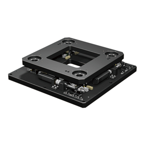
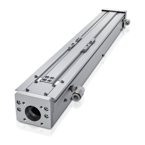
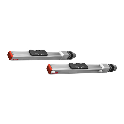
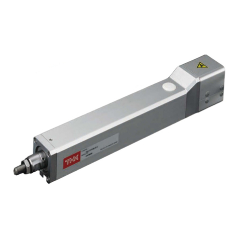
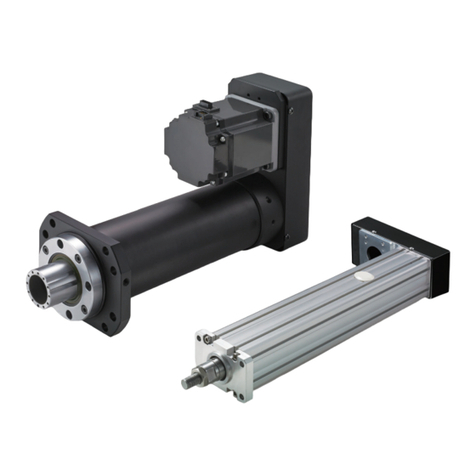
THK ES Series User manual

INSTRUCTION MANUAL
THK Electrical Actuator Economy Series
ES/EC
No.1040-2(0)E

iES/EC
Table of contents
1. Introduction1-2
1-1 Acknowledgment ―――――――――――――――――――――――― 1-2
1-2 About this manual ――――――――――――――――――――――― 1-2
1-3 How to use this product ―――――――――――――――――――― 1-3
1-4 About product support ――――――――――――――――――――― 1-3
1-5 About related instruction manuals―――――――――――――――― 1-3
1-6 About combination of products ―――――――――――――――――― 1-3
1-7 Product and company information――――――――――――――――― 1-3
2. Safety Precautions1-4
2-1 About ranks of precautions―――――――――――――――――――― 1-4
2-2 About description of precautions ――――――――――――――――― 1-4
2-3 Safety precautions ――――――――――――――――――――――― 1-5
3. System Configuration1-7
3-1 System configuration ―――――――――――――――――――――― 1-7
4. Flow Until Using the Product1-8
1. Check the Products2-2
1-1 Check the package contents of ES/EC――――――――――――――― 2-3
1-2 Names of individual parts and functions ――――――――――――― 2-10
1-3 Store and dispose of the products―――――――――――――――― 2-16
2. Precautions on Use2-17
2-1 Precautions on use ES――――――――――――――――――――― 2-17
2-2 Precautions on use EC――――――――――――――――――――― 2-18
3. How to Install2-19
3-1 Installation environment ―――――――――――――――――――― 2-19
3-2 Install ES――――――――――――――――――――――――――― 2-20
3-3 Install EC――――――――――――――――――――――――――― 2-26
1. How to Wire3-2
1-1 Entire wiring ―――――――――――――――――――――――――― 3-3
1-2 Connect actuator cable ――――――――――――――――――――― 3-4
1. Introduction 2. Installation 3. Wiring

ii ES/EC
Table of contents
1. How to Mount the Motor5-2
1-1 ES/EC (direct coupling specification)―――――――――――――――― 5-2
1-2 ES/EC (return specification)―――――――――――――――――――― 5-4
2. Cables5-7
2-1 Connection cable ―――――――――――――――――――――――― 5-7
3. Materials Required for Selecting the Motor5-8
3-1 ES――――――――――――――――――――――――――――――― 5-8
3-2 EC ―――――――――――――――――――――――――――――― 5-9
4. Actuator Combination List5-10
4-1 Combination list―――――――――――――――――――――――― 5-10
1. Maintenance and Inspection4-2
1-1 Daily inspection――――――――――――――――――――――――― 4-2
1-2 Periodical inspection ―――――――――――――――――――――― 4-3
1-3 How to grease up ―――――――――――――――――――――――― 4-4
1-4 Check points when restoring from the long-term suspension ―――― 4-11
2. Repair/Replacement4-12
2-1 How to replace the strip seal ―――――――――――――――――― 4-12
2-2 How to replace the timing belt ――――――――――――――――― 4-14
3. Product Warranty4-16
3-1 Free warranty period―――――――――――――――――――――― 4-16
3-2 Usage conditions (range)―――――――――――――――――――― 4-16
3-3 Warranty scope―――――――――――――――――――――――― 4-16
3-4 Exclusion of warranty liability ―――――――――――――――――― 4-17
3-5 Delivery conditions ―――――――――――――――――――――― 4-17
4. Maintenance and Warranty 5. Technical Materials

1-1 ES/EC
1. Introduction
This section includes intro-
duction about the product
and this manual.
This section includes gen-
eral precautions to follow
when using the product.
Be sure to read this sec-
tion before use and ob-
serve the precautions.
This section includes intro-
duction about peripheral
devices to be used with
this product.
This section describes
installation and setting
processes to make this
product ready for use.
About this chapter
This chapter describes the overview of the product.
This chapter includes information that we want you to check and understand before working with the product.
1. Introduction ………………… 1-1
1-1. Acknowledgment…………………………… 1-2
1-2. About this manual ………………………… 1-2
1-3. How to use this product…………………… 1-3
1-4. About product support …………………… 1-3
1-5. About related instruction manuals ……… 1-3
1-6. About combination of products ………… 1-3
1-7. Product and company information ……… 1-3
2. Safety Precautions ………… 1-4
2-1. About ranks of precautions ……………… 1-4
2-2. About description of precautions ……… 1-4
2-3. Safety precautions ………………………… 1-5
3. System Configuration ……… 1-7
3-1. System configuration ……………………… 1-7
4.
Flow Until Using the Product
… 1-8

1. Introduction
1-2 ES/EC
1-1 Acknowledgment
Thank you for purchasing our product.
This product is a lightweight, compact, and reasonably-priced actuator which ensures a long-term
maintenance-free operation.
This product is designed and manufactured to be incorporated in devices with wide range of ap-
plication including conveyance system, implementing equipment, automated assemblers, and posi-
tioning equipment, etc.
We hope our creative inventions and unique technologies contribute to your further prosperity.
1-2 About this manual
1-2-1 Intended audience
The person in charge of designing embedded systems of the product and installing, wiring, and
maintaining the product, and the person who actually uses the product.
1-2-2 Using this manual
This manual describes correct handling methods and precautions for the product.
For the maximum performance and long life of the product, carefully read and understand this man-
ual to safely and correctly use the product.
If you use the printed version of this manual, be sure to keep it in the place that the audience can
refer to it when needed.
1-2-3 Notice and attention
Do not use or handle the product in the ways that are not described in this manual.
Do not reproduce, reprint, or lend the whole contents or a part of this manual without permission.
Please note that the description in this manual is subject to change without prior notice in the fu-
ture, due to improvements of the product or other reasons.
We have made all possible efforts to make the content of this manual accurate. However, if you
find any mistake or uncertainty in this manual, please contact THK.
Drawings throughout this manual are only intended as typical examples, and may differ from your product.
Note that THK shall not be liable for any result incurred by applying this manual, regardless of the reason.
This manual is also applied to special types of product. However, the descriptions provided in the
delivery specification drawings or delivery specification documents of those special types take
precedence over this manual.
* Special types represent the products that have different materials and specifications from those
of the standard products on catalogs.
1-2-4 Notation of this manual
• Notes that can lead to unsatisfactory function, error, or damage of the product if not observed while using
the product.
• Supplementary information for the description.
• Reference information for the description.
1.
Introduction
Important
Supplement
Reference

1. Introduction
1.
Introduction
1-3 ES/EC
1-3 How to use this product
This product must not be used for the devices or systems that are used under the situations that
may be fatal to human life.
If you consider using this product for special applications such as passenger movement vehicle,
medical, aerospace, nuclear power, and electric power devices or systems, be sure to consult
with THK in advance.
This product is manufactured under the strict quality control, however, that does not mean that
the product is free from failure. For applications to the equipment that may suffer serious acci-
dents or loss from the failure of this product, install safety devices or backup devices that prevent
such serious accidents or loss.
• If you purchase this product with a motor, the driver controller to be used is either TSC or TLC. Please
note that driver controllers other than the above cannot be used.
Important
1-4 About product support
For the following information, please contact THK.
Technical support for this product
1-5 About related instruction manuals
When you use the actuator ES/EC, read the following instruction manuals as necessary.
- Controller series Driver controller TSC
- Controller series Driver controller TLC
- Controller series Network unit TNU
- Controller series Setup tool D-STEP
- Controller series Digital operator TDO
1-6 About combination of products
For information on combination of products, see the list of product combination in Chapter 5 (page
5-10) of this manual.
1-7 Product and company information
To find the latest product and company information, we recommend you to periodically access our
website.
Website URL: http://www.thk.com/
Technical support website URL: https://tech.thk.com/

1-4
1. Introduction
ES/EC
2-1 About ranks of precautions
This manual uses the classifications of "Danger," "Warning," and "Caution" for warning indications
for safety matters.
2-2 About description of precautions
Precautions are classified as "Prohibition," "Instruction," and "Precaution" according to the action.
This mark indicates
"prohibition" of the
action.
This mark indicates
"instruction" for
the action.
This mark indicates
"caution" about
the action.
Prohibited Do not
disassemble
Obligatory Provide grounding
connection
Caution Caution -
Electrical shock
Caution –
Flammable
Caution –
High temperature
Caution –
Getting caught
Danger Erroneous handling may urgently cause death or
serious injury to a person
Warning Erroneous handling may cause death or
serious injury to a person
Caution Erroneous handling may cause injury to a person
or property damage only
2.
Safety Precautions

1-5
1. Introduction
2.
Safety Precautions
ES/EC
2-3 Safety precautions
While the actuator is operating or
operable, do not enter the working
area of any moving part including
the load.
Doing so may cause you to touch the
moving part and get injured.
If the product fails or any abnor-
mality is observed, shut down the
power of the driver controllers TSC
and TLC.
Such abnormality may cause a mal-
function of actuator, resulting in dam-
age or injury.
Do not touch the internal part of
driver controllers TSC and TLC.
Doing so may cause electric shocks.
Do not damage, tuck, or apply ex-
cessive stresses on the cable.
Doing so may cause electric shocks.
Do not modify, disassemble, or al-
ter the product.
Doing so may cause injury or fault.
Prohibited
Obligatory
Caution -
Electrical shock
Do not
disassemble
During the operation, or for a while
after turning the power off, do not
touch the driver controller TSC,
TLC, or motor cover because they
should be hot.
Doing so may cause burns.
Do not impact the product and
do avoid rough handling such as
throwing it.
Doing so may cause the fault or dam-
age that leads to injury.
Do not grasp the strip seal of this
product.
It may injure you.
Some parts of the strip seal may be
sharp. Take care not to cut your hands
or fingers.
Also, the strip seal must be replaced
when it is scratched, pitted or dented.
Use of the strip seal in this state may
cause early breakage or other damages.
Do not frequently switch the power
between on and off.
Doing so may generate heat from the
internal part of driver controller TSC or
TLC, which results in fault or burns.
Do not set the speed or accelera-
tion setting or place the load on
the table that exceed the actuator
specification.
Doing so may cause motor failure,
which leads to unexpected accidents
or damages.
If an alarm is generated, remove
the cause, check the safety, de-
activate the alarm, and restart the
operation.
Failure to do so may result in failure,
which leads to injury.
Caution –
High temperature
Prohibited
Obligatory
Warning
Caution

1-6
1. Introduction
2.
Safety Precautions
ES/EC
Use this product with a combina-
tion that is specified beforehand.
Failure to do so may cause fire or fault.
Observe the specified input volt-
age.
Failure to do so may cause fire or fault.
Caution –
Flammable
Caution

1-7
1. Introduction
ES/EC
3-1 System configuration
The diagram below shows the specification of a combination with the driver controller TSC.
Cables for connecting the devices indicated with ★should be prepared by the customer.
3.
System Configuration
TDO (→*1) PC (D-STEP) (→*2)
Higher device
Emergency stop switch
(This should be pre-
pared by the customer.)
(→*3)
Driver controller
TSC
Actuator cables are provided
with the main unit.
(→P.3-4)
24 V DC power
★
★
★Power supply should
be prepared by the cus-
tomer. Power connector
is provided with TSC.
(→*3)
CN1
CN2
CN4
CN3
CN5
Actuator
PC communication
cables are provided
as an option.
(→*3)
★
I/O connector for CN1 is
provided with TSC.
I/O cables are provided
as an option.
(→*3)
★
*1: See the separate TDO Instruction Manual.
*2: See the separate D-STEP Instruction Manual.
*3: See the separate TSC Instruction Manual.
* When you use 10 m actuator cables,
please install a noise filter for the TSC
power supply.
RSAN-2003 from TDK-Lambda is
recommended for the noise filter.

1-8
1. Introduction
ES/EC
1. Safety check
(1) Safety statement check →P.1-4
(2) Safety check of the installation location
→P.2-19
(3) Installation check →P.2-20, 2-26
2. Preparation (1) Preparation of required devices →P.1-7
(2) Package contents check →P.2-2 to 2-9
3. Installation (1) Installation environment check →P.2-19
(2) Installation →P.2-19 to 2-31
4. Wiring (1) Connection between each device and
cable →P.3-2 to 3-7
5. Trial run and
adjustment
(1) For details of setup tool preparation
and program input, see the separate D-
STEP Instruction Manual.
6. Setup tool setting (1) For details of setup tool setting, see the
separate D-STEP Instruction Manual.
4.
Flow Until Using the Product

2-1 ES/EC
2. Installation
This section describes the
package contents check
and parts of this product.
This section describes the
installation procedures of
this product.
About this chapter
This chapter describes how to check the package contents and to install it to the machine and facilities.
This section is primarily intended for those in charge of installation of this product to a machine and facilities.
1. Check the Products ………… 2-2
1-1. Check the package contents of ES/EC … 2-3
1-2.
Names of individual parts and functions
… 2-10
1-3. Store and dispose of the products ……… 2-16
2. Precautions on Use ……… 2-17
2-1. Precautions on use ES …………………… 2-17
2-2. Precautions on use EC …………………… 2-18
3. How to Install ……………… 2-19
3-1. Installation environment ………………… 2-19
3-2. Install ES …………………………………… 2-20
3-3. Install EC …………………………………… 2-26
This section describes the
precautions on use of this
product.

2. Installation
2-2 ES/EC
Do not stand on the packaging box
or this product.
Doing so may cause malfunction or
damage that leads to injury.
Do not hold ES by pressing the
side covers from both sides when
you carry it.
Doing so may distort the side cover,
which leads to a malfunction.
Do not grasp the strip seal of this
product.
It may injure you.
Some parts of the strip seal may be
sharp. Take care not to cut your hands
or fingers.
Replace the strip seal when it is
scratched, pitted or dented.
Use of the strip seal in this state may
cause early breakage or other dam-
ages.
Prohibited
When carrying the product, do not
hold the cable.
Doing so may cause damage of the
cable that leads to injury.
Do not use the product if you find
any abnormality.
Using a fractured product may cause
malfunction that leads to injury or fault.
If you find any defect, please contact
THK.
Prohibited
Caution
1.
Check the Products
Warning
For the combination of the actua-
tor ES/EC and the driver control-
ler TSC/TLC, do not use actuators
with models other than TSC/TLC.
Doing so may cause unexpected mo-
tions, accidents or failures.
Prohibited
Actuator model: ES4-06-0300B-TS/35P-D00-S3
Driver controller model: TSC-015B-MOD-ES4-06-D
Example of combination
Hold the area indicated
by a red circle from the
bottom.

2. Installation
1.
Check the Products
2-3 ES/EC
1-1 Check the package contents of ES/EC
1-1-1 Check the model/type of the product
Check the model indicated on the product label against the purchase information.
Product label Product label
Slider type ES Cylinder type EC
ES4-06-0300B-TS/35P-D00-S3
XXXXXXXX
Model number( →P.2-4)
Serial number
Necessary for exchanging or repairing the product.

2. Installation
1.
Check the Products
2-4 ES/EC
<Model configuration> Specification of TSC with motor
ES4R -06 -0150 B-TS -ML-GR-SB-L6/35P -D00 -S3
(1) Model number ES3, ES4, ES5, ES6 (Slider type/direct motor coupling)
ES3R, ES4R, ES5R, ES6R (Slider type/motor return)
EC3, EC4 (Cylinder type/direct motor coupling)
EC3R, EC4R (Cylinder type/motor return)
EC3H, EC4H (Cylinder type/direct motor coupling/with linear bush)
(2) Ball screw lead 06: 6 mm
12:
12 mm (ES3, ES3R, EC3, EC3R, and EC3H have the ball screw lead 6 only.)
(3) Stroke 0150 : 150 mm (50 to 600 mm, 50 mm pitch)
The maximum stroke = ES3:300, ES4:400, ES5:500, ES6:600,
EC3:200, EC4:300
(4) Design symbol B
(5) Control device TS: Driver controller TSC
(6) Option No symbol : None
MR : Motor right return*1
ML : Motor left return*1
GR : Change the cover color to gray
SB : With slider base (exclusively for ES)
CB : With cylinder base (exclusively for EC)
FL : With flange (exclusively for EC)
LB : With link ball (exclusively for EC)
□1□2: Sensor (exclusively for ES)*2*3
(7) Motors used 28P: Stepper motor □28, 28PB: Stepper motor □28 with brake
35P: Stepper motor □35, 35PB: Stepper motor □35 with brake
42P: Stepper motor □42, 42PB: Stepper motor □42 with brake
("28P, 28PB": ES3, ES3R, "35P, 35PB": ES4, ES4R, EC3, EC3R, EC3H
"42P, 42PB": ES5, ES5R, ES6, ES6R, EC4, EC4R, EC4H)
(8) Home position D00: Motor side
R00: Reverse motor side
(9) Cable length No symbol : None
S3 : Standard 3 m
S5 : Standard 5 m
SA : Standard 10 m
(1) (7)(4) (5)(3)(2) (6) (8) (9)

2. Installation
1.
Check the Products
2-5 ES/EC
Content Type Accessory
Symbol
□1□2
With sensor rail - - L/R 1
Photo sensor [3 units] EE-SX674 (OMRON Corporation)
Mounting screw/nut, sensor rail (1 pc), mounting
plate (3 pcs), connector (EE-1001, 3 pcs)
L/R 6
Sensor N.O. contact [1 pc] (NPN output)
N.C. contact [2 pcs] (NPN output)
GX-F12A (Panasonic Industrial
Devices SUNX Co., Ltd.)
GX-F12B (Panasonic Industrial
Devices SUNX Co., Ltd.)
Mounting screw/nut, sensor rail L/R J
Sensor N.O. contact [1 pc] (PNP output)
N.C. contact [2 pcs] (PNP output)
GX-F12A-P (Panasonic Industrial
Devices SUNX Co., Ltd.)
GX-F12B-P (Panasonic Industrial
Devices SUNX Co., Ltd.)
Mounting screw/nut, sensor rail L/R M
Note) Please prepare a sensor dog separately since it cannot be installed onto the actuator main unit.
Note) Please note the followings when selecting the product of TSC specification:
・
There is no compatibility between the actuator cable and the stepper driver controller TSC (TSC, hereinafter) of the
existing product and the design symbol B.
You cannot use the actuator main unit/actuator cable of the existing product with the TSC of the design symbol B.
*3 Sensor details
*1 Motor return direction
ML
*2 Sensor installation direction (symbol: R6)
MR

2. Installation
1.
Check the Products
2-6 ES/EC
<Model configuration> Specification of TLC with motor
ES5R -06 -0150 B-TL -ML-GR-SB-L6/M05 L-D00 -F3
(1) Model number ES5, ES6 (Slider type/direct motor coupling)
ES5R, ES6R (Slider type/motor return)
EC4 (Cylinder type/direct motor coupling)
EC4R (Cylinder type/motor return)
EC4H (Cylinder type/direct motor coupling/with linear bush)
(2) Ball screw lead 06: 6 mm
12: 12 mm
(3) Stroke 0150 : 150 mm (50 to 600 mm, 50 mm pitch)
The maximum stroke = ES5:500, ES6:600, EC4:300
(4) Design symbol B
(5) Control device TL: Driver controller TLC
(6) Option No symbol : None
MR : Motor right return*1
ML : Motor left return*1
GR : Change the cover color to gray
SB : With slider base (exclusively for ES)
CB : With cylinder base (exclusively for EC)
FL : With flange (exclusively for EC)
LB : With link ball (exclusively for EC)
□1□2: Sensor (exclusively for ES)*2*3
(7) Motors used M05 :
AC servo motor: 50 W
M05B :
AC servo motor: 50 W (with brake)
(8) Motor cable direction R: Right
U: Up
L: Left
D: Down
(9) Home position D00: Motor side
R00: Reverse motor side
(10) Cable length F3 : 3 m fixed
F5 : 5 m fixed
FA : 10 m fixed
H3 : 3 m high flex
H5 : 5 m high flex
HA : 10 m high flex
For details on *1, *2, or *3, please see *1, *2, or *3 of the previous page (P.2-5) respectively.
Note) Please prepare a sensor dog separately since it cannot be installed onto the actuator main unit.
(1) (7)(4) (5)(3)(2) (6) (8) (9) (10)
(ES: If you select "MR" as an option, "R", "U", or "D"
cannot be selected.
If you select "ML" as an option, "L", "U", or "D"
cannot be selected.)
(EC: If you select "MR" as an option, "R" cannot be
selected.
If you select "ML" as an option, "L"cannot be
selected.)

2. Installation
1.
Check the Products
2-7 ES/EC
<Model configuration> Without motor type
ES4R -06 -0150 B -0-A-ML-GR-SB-L6
(1) Model number ES3, ES4, ES5, ES6 (Slider type/direct motor coupling)
ES3R, ES4R, ES5R, ES6R (Slider type/motor return)
EC3, EC4 (Cylinder type/direct motor coupling)
EC3R, EC4R (Cylinder type/motor return)
EC3H, EC4H (Cylinder type/direct motor coupling/with linear bush)
(2) Ball screw lead 06: 6 mm
12:
12 mm (ES3, ES3R, EC3, EC3R, and EC3H have the ball screw lead 6 only.)
(3) Stroke 0150 : 150 mm (50 to 600 mm, 50 mm pitch)
The maximum stroke = ES3:300, ES4:400, ES5:500, ES6:600, EC3:200, EC4:300
(4) Design symbol B
(5) With/without motor 0: Without motor
1: With motor (purchased from THK)
(6) Intermediate flange*4 N: None
A
B
C
(7) Option No symbol : None
MR : Motor right return*5
ML : Motor left return*5
GR : Change the cover color to gray
SB : With slider base (exclusively for ES)
CB : With cylinder base (exclusively for EC)
FL : With flange (exclusively for EC)
LB : With link ball (exclusively for EC)
□1□2: Sensor (exclusively for ES)*6*7
(1) (4) (5)(3)(2) (6)
*4 Intermediate flange
Motor type
Motor
rated
output
Flange
angle
Intermediate flange model number
ES3 ES4 ES5 ES6 EC3 EC4
Direct
coupling Return Direct
coupling Return Direct
coupling Return Direct
coupling Return Direct
coupling Return Direct
coupling Return
Yasukawa Electric
Corporation
ΣV-mini SGMMV-A2 20 W □25 AA----------
SGMMV-A3 30 W - - A A - - - - A A - -
ΣVSGMJV-A5 50 W □40 - - - - N A N A - - N A
SGMAV-A5 - - - - N A N A - - N A
Mitsubishi Electric
Corporation
J3
HG-AK0236 20 W □25 AA----------
HG-AK0336 30 W - - A A - - - - A A - -
HF-KP053
50 W
□40
- - - - N A N A - - N A
HF-MP053 - - - - N A N A - - N A
J4 HG-KR053 - - - - N A N A - - N A
HG-MR053 - - - - N A N A - - N A
JN HF-KN053 - - - - N A N A - - N A
Panasonic Corporation A5 MSME 5A □38 - - - - B - B - - - B -
OMRON Corporation G5 R88M-K05030 □40 - - - - N - N - - - N -
Oriental Motor
Co., Ltd.
αstep
ARM24* □28B-----------
ARLM46* □42 - - - - C - C - - - C -
ARM46* - - - - C - C - - - C -
5-phase PK523* □28B-----------
RK54* □42 - - - - C - C - - - C -
2-phase PK23* □35 - - B - - - - - B - - -
N model number indicates that you can install a relevant motor without an intermediate flange.
For details on *5, *6, or *7, please see *1, *2, or *3 of P.2-5 respectively.
(7)
* Continue to the next page →

2. Installation
1.
Check the Products
2-8 ES/EC
1-1-2 Check the type and number of accessories
Actuator
Type of parts Qty.
Actuator main unit 1
EC4R (With motor)
Type of parts Qty.
Actuator main unit 1
Supplied nut 1
Square nut 6
Cable list
Type of parts Type Qty.
Actuator cable CBL-TSC-AC-**-B 1
Accessories Material ES3/ES3R ES4/ES4R ES5/ES5R ES6/ES6R
Type Qty. Type Qty. Type Qty. Type Qty.
Slider base Aluminum - 1 - 1 - 1 - 1
Hexagonal-socket-head type bolt
*1
Stainless steel
M3X8L P M4X10L P M4X10L P M4X10L P
Plain washer*1
Stainless steel
Small washer 3
P
Small washer 4
P
Small washer 4
P
Small washer 4
P
Positioning pin*1
Stainless steel
φ2x8L 2 φ3x10L 2 φ3x10L 2 φ3x10L 2
Slider base (ES option)
*1 For assembly with the actuator main unit.
Nominal stroke 50 100 150 200 250 300 350 400 450 500 550 600
P
ES3 3 4 5 6 7 8 - - - - - -
ES4 3 4 5 6 7 8 9 10 - - - -
ES5 4 6 6 8 8 10 10 12 12 14 - -
ES6 4 6 6 8 8 10 10 12 12 14 14 16
Accessories Material EC3 EC4
Type Qty. Type Qty.
Cylinder base Aluminum - 1 - 1
Hexagonal-socket-head type bolt
*2
Stainless steel
M4X16L 4 M4X10L P
Plain washer*2
Stainless steel
Small washer 4
4
Small washer 4
P
Nominal stroke 50 100 150 200 250 300
P EC4 4 4 4 4 6 6
Cylinder base (EC option)
*2 For assembly with the actuator main unit.
Accessories Material EC3/EC3R EC4/EC4R
Type Qty. Type Qty.
Flange Aluminum - 1 - 1
Hexagonal-socket-head type bolt
*3
Stainless steel M4X16L 4 M6X25L 4
Plain washer*3 Stainless steel
Small washer 4
4
Small washer 6
4
Flange (EC option)
*3 For assembly with the actuator main unit.
ES □(With/without motor)
ES □R(Without motor)
Type of parts Qty.
Actuator main unit 1
Timing pulley 1
Timing belt 1
Type of parts Qty.
Actuator main unit 1
ES □R(With motor)
EC3/EC3H
(With/without motor)
Type of parts Qty.
Actuator main unit 1
Supplied nut 1
EC3R (With motor)
Type of parts Qty.
Actuator main unit 1
Supplied nut 1
EC3R (Without motor)
Type of parts Qty.
Actuator main unit 1
Supplied nut 1
Timing pulley 1
Timing belt 1
EC4R (Without motor)
Type of parts Qty.
Actuator main unit 1
Supplied nut 1
Square nut 6
Timing pulley 1
Timing belt 1
EC4/EC4H
(With/without motor)
Type of parts Qty.
Actuator main unit 1
Supplied nut 1
Square nut 6
** is cable length. (03: 3 m, 05: 5 m, 10: 10 m)

2. Installation
1.
Check the Products
2-9 ES/EC
For any special type, check against the delivery specification documents.
After the checking, keep the product packed in the packaging box until the start of installation work.
1-1-3 Check the product for any damage or abnormality
Reference
This manual suits for next models
15
Table of contents
Other THK Controllers manuals
Popular Controllers manuals by other brands

DeVilbiss
DeVilbiss 130516 Assembly guide
Panasonic
Panasonic SL-VGU1-C user manual

Ploom
Ploom PX1 user guide

Go Power
Go Power GPR-25 owner's manual
Rockwell Automation
Rockwell Automation 1785 PLC-5 quick reference
Dwyer Instruments
Dwyer Instruments Digihelic DHC Series Installation and operating instructions
