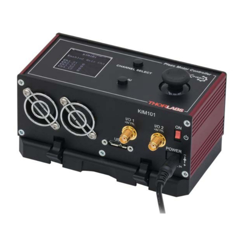
PDXC ORIC® Piezo Stage Controller
Table of Contents
Chapter 1 Warning Symbol Definitions.............................................................................................. 1
Chapter 2 Safety .................................................................................................................................... 2
Chapter 3 Overview............................................................................................................................... 3
3.1. Introduction .....................................................................................................................3
3.2 Operation Principle.........................................................................................................3
3.3 Stages Connection and Accessories ...............................................................................4
3.3.1 Operation Elements ................................................................................................................6
3.3.2 Front Panel..............................................................................................................................6
3.3.3 Back Panel............................................................................................................................7
Chapter 4 Panel Operation..................................................................................................................10
4.1. Getting Started ..............................................................................................................10
4.2. D-Sub Output Mode.......................................................................................................10
4.2.1. Move Stage in Closed-Loop Operation...............................................................................11
4.2.2. Set Velocity in Closed-Loop Operation...............................................................................11
4.2.3. Move Stage in Open-Loop Operation.................................................................................12
4.2.4. Set Velocity in Open-Loop Operation .................................................................................12
4.2.5. Set Step Size in Open-Loop Operation...............................................................................13
4.2.6. Save Parameters in D-Sub Mode .......................................................................................14
4.2.7. Homing................................................................................................................................15
4.2.8. Encoder Calibration.............................................................................................................16
4.3. SMC Output Mode .........................................................................................................17
4.3.1. Channel Selection...............................................................................................................18
4.3.2. Setting Velocity Value.........................................................................................................18
4.3.3. Set Step Size ......................................................................................................................19
4.3.4. Save Parameters ................................................................................................................20
4.4. Over Current Protection ...............................................................................................21
4.5. Firmware Update...........................................................................................................21
Chapter 5 Software...............................................................................................................................23
5.1. D-Sub Output Mode.......................................................................................................23
5.1.1. D-Sub Output Mode Main Menu .........................................................................................23
5.1.2. Device Status Buttons.........................................................................................................25
5.1.3. Move Stage.........................................................................................................................25
5.1.4. Position Range Limit...........................................................................................................25
5.1.5. Loop switch .........................................................................................................................25
5.1.6. External Trigger Mode.........................................................................................................26
5.2. SMC Output Mode .........................................................................................................27
5.3. Daisy-Chain Operation..................................................................................................28
5.3.1. Physical Connection and Set-up.........................................................................................29
5.3.2. Set Device ID and Connect.................................................................................................29
5.3.3. Daisy-Chain Operations......................................................................................................32
5.4. Raster Scan Operation..................................................................................................33
5.4.1. Physical Connections..........................................................................................................33
5.4.2. Operation of Scan...............................................................................................................34
