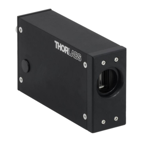
Soleil-Babinet Compensator
Table of Contents
Chapter 1 Introduction ........................................................................................................................1
Chapter 2 Setup ...................................................................................................................................2
2.1. Unpacking..................................................................................................................... 2
2.2. Basic Compensator Operation .................................................................................... 2
2.2.1. Digital Micrometer ................................................................................................................. 2
2.2.2. Graduated Rotation Dial ........................................................................................................ 2
2.2.3. 45° Detent Stops ................................................................................................................... 2
2.2.4. Kinematic Azimuth/Elevation (Tip/Tilt) Adjustment ............................................................... 2
2.3. Using Compensator with Crossed Polarizers............................................................. 3
2.4. Calibration..................................................................................................................... 4
2.4.1. Calibration Procedure ........................................................................................................... 4
Chapter 3 Setting the Compensator to a Specific Retardance ......................................................6
3.1. Setting the Compensator at the Calibration Wavelength........................................... 6
3.2. Setting the Compensator for other Wavelengths....................................................... 6
Chapter 4 Measuring an Unknown Retardance/Birefringence.......................................................7
Chapter 5 Optional LabVIEW Software and Serial Support............................................................8
5.1. Serial Interface Setup................................................................................................... 8
5.2. Software Installation..................................................................................................... 8
5.2.1. Stand-Alone Version ............................................................................................................. 8
5.2.2. LabVIEW Drivers ................................................................................................................... 9
5.3. Software Operation....................................................................................................... 9
5.3.1. Overview ............................................................................................................................... 9
5.3.2. User Interface Fields ........................................................................................................... 10
5.3.3. Stand-Alone Version ........................................................................................................... 11
5.3.4. Calibrating the Compensator .............................................................................................. 12
5.3.5. Setting the Compensator to a Target Retardance .............................................................. 13
5.3.6. Quitting the Stand-Alone Version ........................................................................................ 13
5.3.7. Running the Compensator Software with LabVIEW ........................................................... 13
Chapter 6 Theory of Operation ........................................................................................................14
Chapter 7 Cleaning and Maintenance .............................................................................................16
7.1. Cleaning the Optics.................................................................................................... 16
7.2. Cleaning the Compensator Housing......................................................................... 16
7.3. Micrometer Battery Replacement.............................................................................. 16
Chapter 8 Specifications...................................................................................................................17
Chapter 9 Mechanical Drawing ........................................................................................................18
Chapter 10 Regulatory ........................................................................................................................19
10.1. Waste Treatment is Your Own Responsibility .................................................. 19
10.2. Ecological Background ...................................................................................... 19
Chapter 11 Thorlabs Worldwide Contacts........................................................................................20
