manuals.online logo
Brands
  1. Home
  2. •
  3. Brands
  4. •
  5. THORLABS
  6. •
  7. Security Sensor
  8. •
  9. THORLABS PDA500 Manual

THORLABS PDA500 Manual

2922-D02 Rev C 8/2/00
Page 1of 3
PO Box 366, 435 Route 206N, Newton, NJ 07860
Ph (973) 579-7227, Fax (973) 383-8406, http://www.thorlabs.com
Operating Manual PDA500 - Switchable Gain, Amplified GaAsP Detector
Description:
The PDA500 is an amplified, switchable-gain, GaAsP detector designed for detection of light signals from DC to 200
kHz. A five-position rotary switch allows the user to vary the gain in 10 dB steps. A buffered output drives a 50Ωload
impedance up to 5 volt. The PDA500 housing includes a removable threaded coupler that is compatible with any
number of Thorlabs 1” threaded accessories. This allows convenient mounting of external optics, light filters
apertures, as well as providing an easy mounting mechanism using the Thorlabs cage assembly accessories.
The PDA500 has an 8-32 tapped mounting hole with a 0.25” mounting depth and includes a 120VAC power AC/DC
supply. The PDA500-EC has a M4 tapped mounting hole and includes A 230VAC AC/DC power supply.
Specifications:
Note 1: The PDA500 has a 50Ωseries terminator resistor (i.e. in series with amplifier output). This forms a voltage
divider with any load impedance (e.g. 50Ωload divides signal in half).
Setup
•Unpack the optical head, install a Thorlabs TR-series ½” diameter post into the 8-32 (M4 on -EC version) tapped
hole on the bottom of the head, and mount into a PH-series post holder. Note: Do not install a mounting post
more than ¼” into the housing. This will damage the unit.
•Plug the 5-pin DIN plug on the power supply provided with the PDA500 into the mating jack on the PDA500.
•Plug the power supply into an 50-60Hz, 100-120VAC outlet (220-240VAC for -EC version).
Detector Performance min typical max
Detector GaAsP 0 dB Setting
Active Area 1.3 x 1.3 mm Transimpedance Gain11.5 x 104V/A
Response 300 to 680 nm Trans. Gain (50Ω)10.75 x 10⁴V/A
Peak Response 0.3 A/W @ 640 nm Bandwidth 150 kHz
Bandwidth DC to 150kHz Noise (RMS) < 100 µ
µµ
µV
NEP (640nm, 0dB) 60 x 10-12 W/√
√√
√Hz Offset -5 mV 4.5 mV 15 mV
NEP (640nm, 10dB) 20 x 10-12 W/√
√√
√Hz 10 dB Setting
NEP (640nm, 20dB) 9 x 10-12 W/√
√√
√Hz Transimpedance Gain14.7 x 104V/A
NEP (640nm, 30dB) 6 x 10-12 W/√
√√
√Hz Trans. Gain (50Ω)12.35 x 10⁴V/A
NEP (640nm, 40dB) 4 x 10-12 W/√
√√
√Hz Bandwidth 150 kHz
Output Voltage(50Ω)10 to 5V Noise (RMS) 130 µ
µµ
µV
Output voltage1. 0 to 10V Offset -5 mV 5 mV 15 mV
Output Impedance150 ohms 20 dB Setting
Load Impedance1. Hi -Z to 50 ohms Transimpedance Gain11.5 x 105V/A
Gain Steps 0, 10, 20, 30, 40 dB Trans. Gain(50Ω)10.75 x 10⁵V/A
Gain Switch 5-Pos Rotary Bandwidth 150 kHz
On / Off Switch Toggle Noise (RMS) 170 µ
µµ
µV
Output BNC Offset -10 mV 6.5 mV 20 mV
Damage Threshold 100mW CW 30 dB Setting
0.5J/cm210ns PW Transimpedance Gain14.7 x 105V/A
Optical Head Size φ
φφ
φ1.5” x 0.79” Trans. Gain (50Ω)12.35 x 10⁵V/A
Weight 60 grams Bandwidth 100kHz
Accessories SM1T1 Coupler Noise (RMS) 250 µ
µµ
µV
Storage Temp -20 to 80°
°°
°COffset -20 mV 11 mV 50 mV
Operating Temp -10 to 60°
°°
°C40 dB Setting
AC Power Supply AC - DC Converter Transimpedance Gain11.5 x 106V/A
Input Power 100-120VAC, Trans. Gain(50Ω)10.75 x 10⁶V/A
(220-240VAC-EC Bandwidth 45kHz
version) Noise (RMS) 400 µ
µµ
µV
50-60Hz, 5W Offset -100 mV 25 mV 100 mV
2922-D02 Rev C 8/2/00
Page 2of 3
•Attach a 50Ωcoax cable (i.e. RG-58U) to the output of the PDA. When running cable lengths longer than 12” we
recommend terminating the opposite end of the coax with a 50Ωresistor (Thorlabs p/n T4119) for maximum
performance.
Operation
•The gain of the PDA500 is adjusted using a small slotted screwdriver to turn the internal, gain-setting rotary
switch. An access hole labeled GAIN is provided on the rear panel for this purpose. When the slot is aligned
vertical with the housing, the gain is at 0dB. Also, the switch has a physical stop at the 0dB setting. If in doubt,
turn the switch counter-clockwise until it stops. At that point the gain is at 0dB. Each click of the switch clockwise
increases the gain by 10 dB. Do not use excessive force when adjusting the gain switch.
•The PDA500 is switched on by the POWER toggle switch on the rear of the head.
•The light to voltage conversion can be estimated by factoring the wavelength-dependent responsivity of the
silicon detector with the transimpedance gain
(E.g. output in volts / watt = transimpedance gain (V/A) x responsivity (A/W) )
•The maximum output of the PDA500 is 10 volts (for high impedance loads). Adjust the gain so that the measured
signal level out of the PDA500 is below 10 volts (5 volts with a 50Ωload) to avoid saturation. If necessary, use
external neutral density filters to reduce the input light level.
•For maximum linearity performance when measuring focused beams, fiber outputs, or small diameter beams, do
not exceed a maximum intensity of 10mW/cm2.
•Because of the finite gain-bandwidth performance common to all amplifier circuits, the bandwidth of the PDA500
goes down with increased gain settings.
Fiber Adapters and Other Accessories
Thorlabs sells a number of accessories that are compatible with the 1” thread on the PDA housing including FC,
SMA, and ST fiber adapters, stackable lens tubes for mounting optics, and cage assemblies that allow the PDA to be
incorporated into elaborate 3-D optical assemblies.
Caution: The PDA500 was designed to allow maximum accessibility to the photodetector by
having the front surface of the diode to extend outside of the PDA housing. When
using fiber adapters be sure that the fiber ferrule does not crash into the detector to avoid damage to the diode and or
the fiber. An easy way to accomplish this is to install a SM1RR retaining ring (included with the PDA500) inside the 1”
threaded coupler before installing the fiber adapter.
Also available are Germanium, InGaAs, and Silicon models of the PDA series.
Gain Switch
position Gain
(dB) Transimpedance Gain
(V/A)
1 0 1.5 x 10⁴
2 10 4.7 x 10⁴
3 20 1.5 x 10⁵
4 30 4.7 x 10⁵
5 40 1.5 x 10⁶
Table 1. Gain Settings
Figure 1. Detector Responsivity
2922-D02 Rev C 8/2/00
Page 3of 3
Maintaining the PDA500
There are no serviceable parts in the PDA500 optical head or power supply. The housing can be cleaned by wiping
with a soft damp cloth. The window of the detector should only be cleaned using optical grade wipes. If you suspect a
problem with your PDA500 please call Thorlabs and an engineer will be happy to assist you.

Other THORLABS Security Sensor manuals

THORLABS DET10A User manual

THORLABS

THORLABS DET10A User manual

THORLABS DET Series User manual

THORLABS

THORLABS DET Series User manual

THORLABS PDA10JT User manual

THORLABS

THORLABS PDA10JT User manual

THORLABS DET100A2 User manual

THORLABS

THORLABS DET100A2 User manual

THORLABS APD430 Series User manual

THORLABS

THORLABS APD430 Series User manual

THORLABS APD130 Series User manual

THORLABS

THORLABS APD130 Series User manual

THORLABS PDA10PT User manual

THORLABS

THORLABS PDA10PT User manual

THORLABS PDA10D User manual

THORLABS

THORLABS PDA10D User manual

THORLABS PDAPC2 User manual

THORLABS

THORLABS PDAPC2 User manual

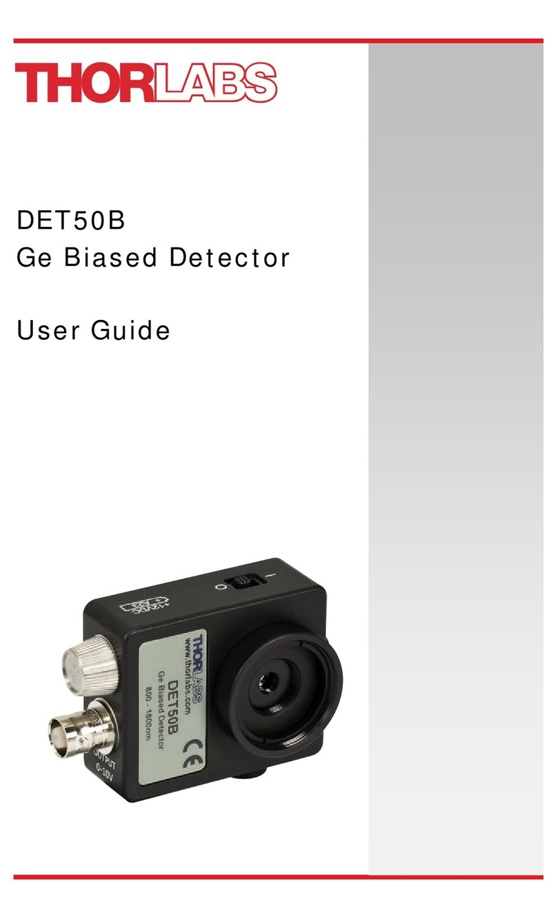
THORLABS DET50B User manual

THORLABS

THORLABS DET50B User manual

THORLABS APD440A User manual

THORLABS

THORLABS APD440A User manual

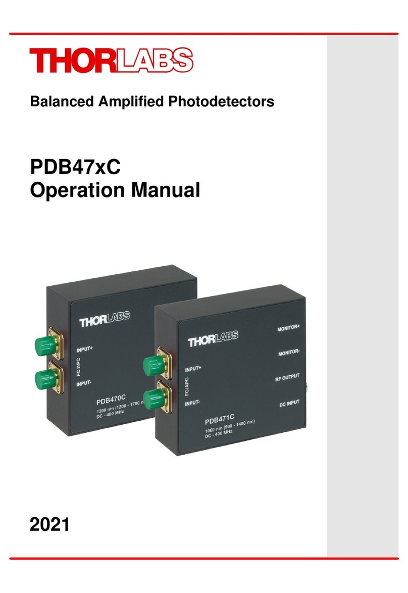
THORLABS PDB47 C Series User manual

THORLABS

THORLABS PDB47 C Series User manual

THORLABS PDA05CF2 User manual

THORLABS

THORLABS PDA05CF2 User manual

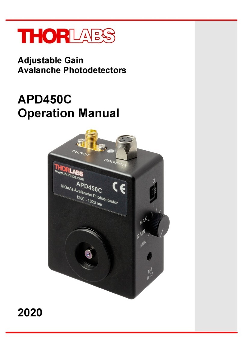
THORLABS APD450C User manual

THORLABS

THORLABS APD450C User manual

THORLABS DET10D2 User manual

THORLABS

THORLABS DET10D2 User manual

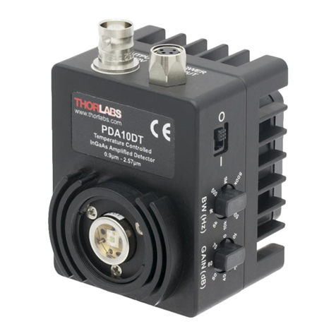
THORLABS PDA10DT User manual

THORLABS

THORLABS PDA10DT User manual

THORLABS DET10A2 User manual

THORLABS

THORLABS DET10A2 User manual

THORLABS DET01CFC User manual

THORLABS

THORLABS DET01CFC User manual

THORLABS SPDMA User manual

THORLABS

THORLABS SPDMA User manual

THORLABS PDA10D2 User manual

THORLABS

THORLABS PDA10D2 User manual

THORLABS LSS10 User manual

THORLABS

THORLABS LSS10 User manual

THORLABS SIR5-FC User manual

THORLABS

THORLABS SIR5-FC User manual

THORLABS PDA20CS2 User manual

THORLABS

THORLABS PDA20CS2 User manual

THORLABS PDAVJ series User manual

THORLABS

THORLABS PDAVJ series User manual

Popular Security Sensor manuals by other brands

jablotron JA-85P quick start guide

jablotron

jablotron JA-85P quick start guide

ESYLUX DEFENSOR MD 200 24 IR 1C IP55 WH operating instructions

ESYLUX

ESYLUX DEFENSOR MD 200 24 IR 1C IP55 WH operating instructions

AUS PRO CL-200E user manual

AUS

AUS PRO CL-200E user manual

Omron F3SG series user manual

Omron

Omron F3SG series user manual

RAPITEST WPS 115 manual

RAPITEST

RAPITEST WPS 115 manual

PROEM CIR20AV Installation Notice

PROEM

PROEM CIR20AV Installation Notice

netvox ZB11C user manual

netvox

netvox ZB11C user manual

Rielta Pyrone-7 installation guide

Rielta

Rielta Pyrone-7 installation guide

EMX Industries CarSense202 CS202 instruction manual

EMX Industries

EMX Industries CarSense202 CS202 instruction manual

Petzl VIZEN manual

Petzl

Petzl VIZEN manual

schmersal EX-AZM 415 operating instructions

schmersal

schmersal EX-AZM 415 operating instructions

LinMot DM01-23-FS installation guide

LinMot

LinMot DM01-23-FS installation guide

System Sensor 1424 Installation and maintenance instructions

System Sensor

System Sensor 1424 Installation and maintenance instructions

Saso SASO PB100A installation instructions

Saso

Saso SASO PB100A installation instructions

iRay Technology Mars1717XF Series user manual

iRay Technology

iRay Technology Mars1717XF Series user manual

Hytronik HIR22 manual

Hytronik

Hytronik HIR22 manual

Tecnoalarm MINIEXPLORER manual

Tecnoalarm

Tecnoalarm MINIEXPLORER manual

Reer JANUS Quick installation guide

Reer

Reer JANUS Quick installation guide

manuals.online logo
manuals.online logoBrands
  • About & Mission
  • Contact us
  • Privacy Policy
  • Terms and Conditions

Copyright 2025 Manuals.Online. All Rights Reserved.