ThyssenKrupp Flow2A User manual

Flow2A chairlift
Installation manual

© 2015 ThyssenKrupp Accessibility BV
Version 2.0
All rights reserved.
Specifications and illustrations are subject to change without prior notice. ThyssenKrupp Accessibility
BV will not accept liability for any alteration or typing error.
Subject to the exceptions provided by law, this publication and/or its contents may not be, whether
entirely or partly, reproduced, copied, and/or published in print, by photocopying, on microfilm,
electronically or in any other way without the prior written consent of ThyssenKrupp Accessibility BV.

Table of contents
1Preparations......................................................................................................................4
1.1 At the branch..............................................................................................................4
1.2 At the customer’s home...............................................................................................4
2Installing the rail.................................................................................................................5
2.1 Fitting the legs and brackets.........................................................................................5
2.2 Connecting the rail sections with a section bush .............................................................7
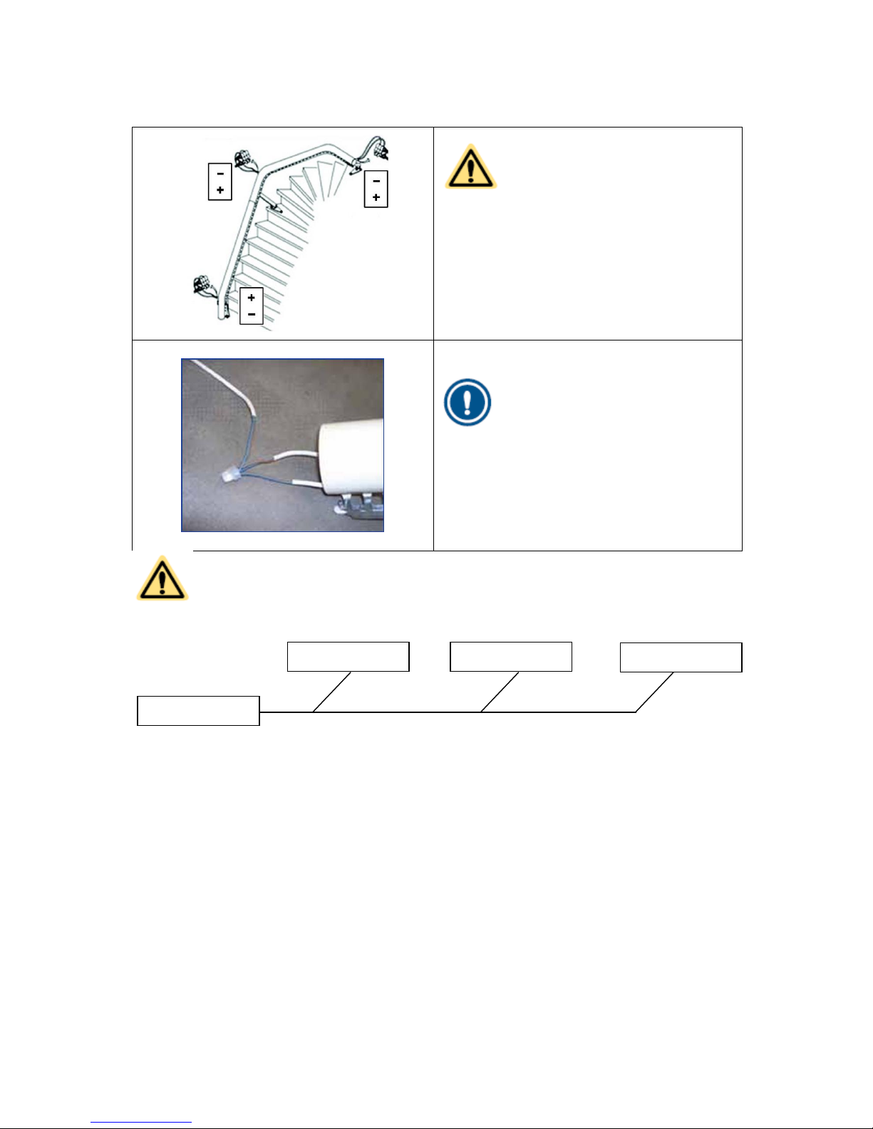
2.3 Installing the feeder cable ............................................................................................7
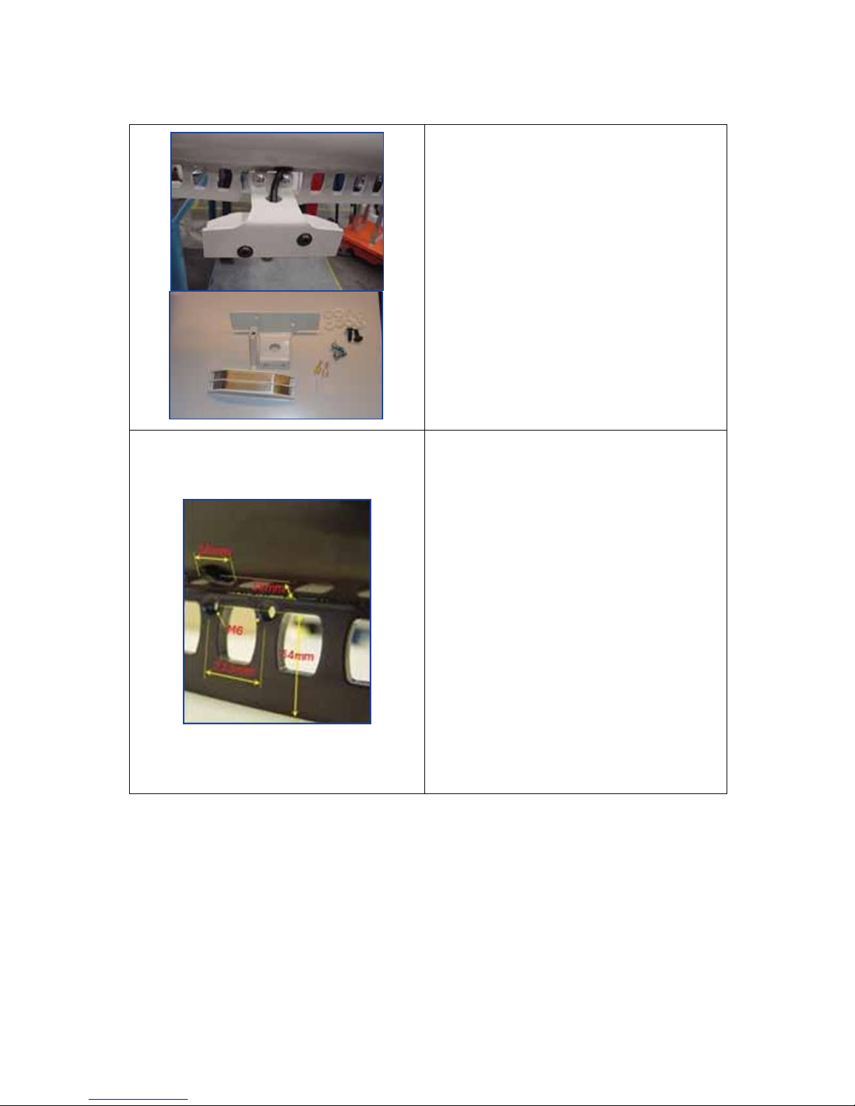
2.4 Fitting and installing the charging contacts.....................................................................8
2.4.1 Fixed charging contacts ........................................................................................8
2.4.2 Movable charging contacts....................................................................................9
2.4.3 Connection of charging contacts..........................................................................10
2.5 Connecting and mounting the transformer ...................................................................11
2.6 Positioning the rail.....................................................................................................11
2.7 Greasing the rail........................................................................................................11
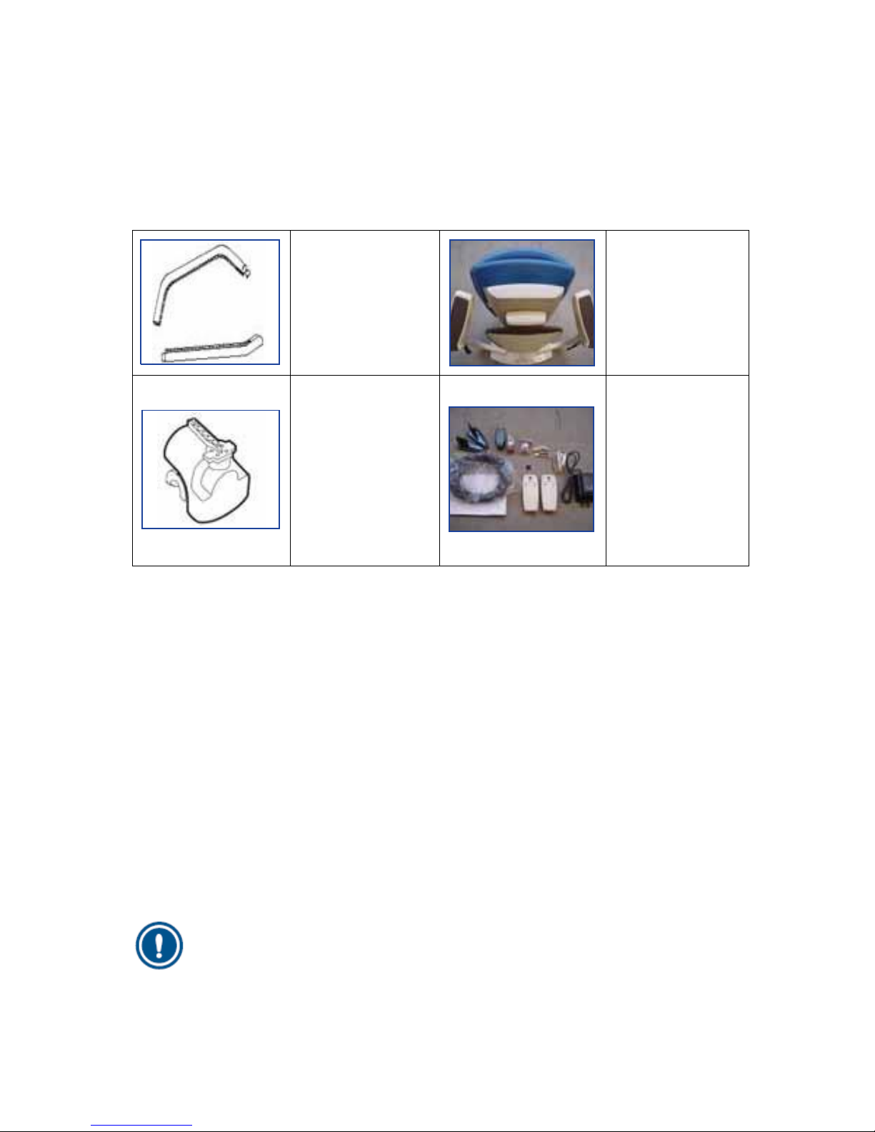
3Assembly ........................................................................................................................12
3.1 Prepare drive unit......................................................................................................12
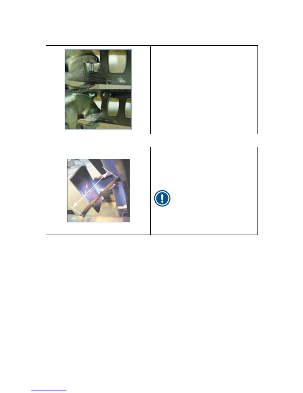
3.2 Drive onto the rail......................................................................................................14
3.3 Calibration of level sensors.........................................................................................15
3.4 Basic installation with rail data....................................................................................15
3.5 Preparing the drive unit for use...................................................................................16
3.6 Fit the chair base ......................................................................................................16
3.7 Installing the manual swivel seat fitting........................................................................17
3.8 Chair base height adjustment .....................................................................................18
3.9 Height of the footrest.................................................................................................19
3.10 Adjusting the length of the safety belt..........................................................................20
3.11 Fixing the rail to the stairs ..........................................................................................20
3.12 Registering controls...................................................................................................21
3.13 Setting mode -8-, Assign Call/Park..............................................................................22
3.14 Safe point ................................................................................................................23
3.15 Installation without raildata provided ...........................................................................23

4
1Preparations
1.1 At the branch
Check using the installation drawings and the shipping receipt whether all the required parts of the
drive unit are present and undamaged, especially:
The rail sections and
the section bushes.
The chair base with
control unit.
The drive unit.
Various loose
components, such
as: call and park
units with joysticks,
transformer, flash
card, two-core power
cable, charging
contacts, rail
brackets with fixing
materials and an
installation drawing.
Consult the installation drawing and the bill of materials to check:
the colour of the rail.
the type and colour of the upholstery.
1.2 At the customer’s home
Inspect the area in which you plan to install the stairlift to verify that all the necessary and
agreed structural alterations have been carried out. If these alterations have not been carried
out, then you should consult the Chief Engineer or the Service Manager.
Inspect the area where you plan to install the drive unit for damage. Inform the customer of
any damage you find, and make a note on the requisite form. Have the customer sign the
form.
To ensure that you will be able to work without having to wait, you will need to go through all
the points for which you need information from the customer, i.e.:
oWhat is the best position for the transformer?
oWhat is the best place for the call and park units?
oIs there anything that you will need to remove or relocate (such as a painting, or a hat
rack)?
oAre there any structural points you will need to take into account?
NOTE
Give the
customer
the user's manual to read right away.

5
2Installing the rail
During the preassembly you fit the entire rail together without fixing it to the stairs.
1. Sort the rail sections, brackets and legs by number (refer to the installation drawing).
2. Assemble the rail section for section from the bottom of the stairs to the top:
a. Fit the relevant legs and brackets to the rail section.
b. Insert a section bush into the upper end of the rail section.
c. Lay the rail section in position and draw the feeder cable for the charging contacts through
the rail section. When charging contacts are to be fitted to the relevant rail section make
sure that the feeder cable projects from the position of the charging contacts, and then
draw the remainder through the rail section.
d. Slide the rail section over the section bush of the previous rail section and clamp the
section bush.
e. Drive a locking pin into the rack coupling.
f. Repeat steps a to e inclusive for the next rail section.
g. Fit a cap to the top and bottom ends of the rail.
h. Assemble and install the charging contacts.
i. Connect the transformer.
j. Position the rail.
NOTE
The above is a recommended sequence. Usually, assembly from the bottom to the
top will be preferable; however, this is not always the case. Decide for yourself which
one you find is the simplest.
CAUTION
Ensure that the locking pin is securely seated in the rack coupling, it must not
protrude underneath the rail.
2.1 Fitting the legs and brackets
Three types of brackets are used:
Floor brackets (for a vertical stop at the bottom of the stairs).
Tread brackets (on the stairs).
Landing brackets (for landings and horizontal sections).
CAUTION
Fit the legs and brackets solely to the rail sections. Do not fix them to the stairs yet.

6
The floor bracket:
1. Insert two hammer-head bolts (1) in the
openings in the rail flange (2).
2. Fix the floor bracket (3) to the rail flange with
the two hammer-head bolts and two
Tensilock nuts (4).
The tread brackets:
1. Prepare the support if necessary.
2. Fit the leg (12) to the foot (10). Do this by
assembling the M10 bolt (13) and locknut
(9).
3. Screw the bolt (7) and washer (11) into the
wedge in the leg (12) with the rail bracket (6)
between them at the right height.
CAUTION
Always fit the nut out of sight on the side
facing the wall. Fit the bolt on the side facing
the stairs.
The landing brackets:
1.
Fix the landing bracket (14) to the rail flange
(16) with two Tensilock bolts (15).

7
2.2 Connecting the rail sections with a section bush
1. Tighten (loosely) the four socket-head screws
in the section bush so that the four nuts are
trapped in the slot on the inner surface.
2. Fit the section bush in the end of a rail
section and adjust it to the correct position.
3. Lock the section bush by tightening the first
socket-head bolt (do not over-tighten).
4. Slide the other rail section over the section
bush and make sure that the two sections
mate properly.
5. Position a locking pin in the uppermost hole
in the rail section.
6. Push the locking pin using a welding clamp
or adjustable wrench into the rack.
2.3 Installing the feeder cable
1. Pull the two-core feeder cable with a cable
puller through the rail section tube.
2. Pull the feeder cable through the opening in
the flange for the charging contacts. Ensure
that the length through the rail hole L is
approximately 20 cm.
NOTE
A rail section with a parking point will be
fitted with an extra bracket with a feed-
through opening. The two-conductor feeder
cable must also be fed to this.

8
2.4 Fitting and installing the charging contacts
2.4.1 Fixed charging contacts
The positions of the fixed charging contacts are
prepared on the rail at the factory. The charging
contact is installed as follows:
1. Strip approximately 9 cm of the feeder cable.
2. Attach a Faston connector to the cable ends.
3. Feed the cables through the charging
contact.
4. Secure the Faston connector on the lips in
the charging contact.
5. Fit the charging contact to the rail with (2x)
M6x16.
6. Adjust the position of the charging contact so
that it is in line with the drive unit spring
contact. Adjustment is always necessary for
a vertical start.
7. For the polarity of the contacts, please see
section 2.4.3

9
2.4.2 Add-on charging contacts
There are also charging contacts that can be
fitted afterwards by a technician. The bracket for
this charging contact is attached to the rail with
two screws.
Make sure that when you order this charging
contact you also specify the color of the rail.
Only mount the movable charging contact at the
following places:
straight sections of the rail.
vertical bends in the rail.
horizontal bends in the rail.
The bracket cannot be mounted on combined
bends (Spirals). The center of the bracket must
be a minimum of 130 mm from the beginning or
end of a Spiral.
Fit this charging contact as follows:
1. Select a hole in the tooth rack to which the
movable charging contact can be fitted.
2. Drill holes (5 mm) next to this hole in the
tooth rack (23.5 mm apart, 34 mm to
underside of rack) for attachment of the
bracket.
3. Tap these holes with M6 threads.
4. Drill a hole (16 mm) in the rail for the cable
feed-through (15 mm from the tooth rack).
5. Fit the supplied rubber grommet in the hole
through the rail.
6. Fit the bracket to the tooth rack using the two
screws and two spacers.
7. Connect the charging contact and fit the
charging contact on the bracket.
8. Feed the wiring through the grommet and
through the tube and connect the wiring to
the power supply.
9. Adjust the position of the charging contact so
that it is in line with the drive unit spring
contact.

10
2.4.3 Connection of charging contacts
CAUTION
The connections to the + and - terminals
of the bottom charging contacts must be
reversed as compared to those of the
other charging contacts. This is
necessary to enable the drive unit to
detect that it has reached the bottom of
the stairs and must stop. This is the so-
called reset point.
NOTE
For the parallel connection of multiple
charging contacts, the cables can be
connected with splice connector. When
there are several floors, the connection
can best be made at the junction.
CAUTION
Only use original supplied transformer.
Transformer
Charging contact
Charging contact
Charging contact

11
2.5 Connecting and mounting the transformer
1. Connect the transformer to the charging contacts closest to a 230Vac wall socket. Use an
extension lead if necessary.
2. Put the transformer plug in the wall socket.
3. Check that the voltage is approximately 33 V and the connection is as indicated in the figures
above.
4. Connect the building wires from the charging contacts to the transformer.
5. Choose a suitable position for the transformer and secure it with four screws and washers.
NOTE
Instead of extending the mains cable you can also extend the building wire and then
fix it out of sight.
Remove the plug from the wall socket.
2.6 Positioning the rail
1. Check the adjustment positions 'X', 'Y' and 'Z'
using the installation drawing. The
adjustment dimensions are measured from
the wall or a tread to the center of the rail’s
pipe.
2. Check the angles and dimensions of the rail
against the installation drawing.
3. Locate the rail in the optimum position.
4. Adjust the legs and brackets such that the
rail is stable on the stairs. Insert one or more
spacers between the legs and the rail if so
required.
2.7 Greasing the rail
1. For greasing, use Super Lube grease and
spread it on the rail with a brush.
Grease the bearing surfaces in the holes.
Grease the support wheel running
surface.

12
3Assembly
CAUTION
Take ESD precautions, such as a mat, strap and shoes. Never touch a circuit board
without taking these precautions.
3.1 Prepare drive unit
1. Place the box with drive unit near the location
where it will be driven onto the rail.
2. Use the top protection cover to put the drive
on the floor.
3. Lift the drive out of the box using the handle
bar on top.
CAUTION
Before powering up the system, make sure it is at room temperature of the
environment where it will be installed.

13
Before putting in the fuse, please check that all
connectors are properly connected to the
control board, service board and sensor board.
Remove the front (service) cover and put the 30A
fuse into the drive (right side next to battery) and
switch the drive on by slightly pulling out the red
tab on the back. (A spark is normal when
inserting the fuse)
Check that the blue led on the front is lit. Enter
service mode:
Press the middle (E - enter) button at least 5
seconds, until 0.00 appears in the display.
The number with the dot next to it can be
altered, left button -> “D” - decrement, right
button -> “I” - increment. The digit can be
selected by moving the dot with the Enter
button from left to right.
Enter the password: “245” with use of the
buttons (e.g. press “I”-increment twice for
number 2, repeat for 4 and 5).
Now enter the service mode by pressing the
middle button again for 5 seconds.
You should now be in service mode -2-.
The horizontal lines next to the number 2 are
blinking, indicating that you are in the main
menu.
By pressing the “D” and “I” buttons a menu
can be selected.
For installation, press the “I” button once, so
-3- is displayed.
Now press the “E” button to enter mode -3-.
The horizontal lines next to the number 3 are
now continuous lit.
The lift will go out of the service modes when no command has been given for 5 minutes, it will then
return to normal operation mode.
The password does not have to be re-entered when going through service modes and resetting the lift,
as long as the lift doesn’t go into sleep mode after 2 minutes of no operation (while in normal
operation mode) or has been driven for 5 minutes.

14
3.2 Drive onto the rail
1. Position the drive next to the rail, facing front
as how it should be when it is on the rail.
Now lift up one of the bogie half (The one
opposite of the rail) and pull it to the top until
it will not go further.
2. Push the other bogie half onto the rail, (using
your leg if needed) and lifting the drive by its
handle. Now you can drive the main gear by
pressing the button on the front of the handle
in the direction you want to drive. Drive the
lift onto the rail, and make sure the forks on
the bottom of the lift, near the charging
contact are in line with the rack.
3. Once the main gear runs into the rack, check
the forks again, so they are still in line with
the rack. Slowly, one bit at the time drive the
unit further onto the rail, checking that
everything is aligned, until the second bogie
half set it fully onto the rail. Now disconnect
the handlebar from the mainboard and
connect an installation joystick to the 3 pin
connector.
4. Now disconnect the handlebar from the
controlboard and connect an installation
joystick to the 3 pin connector. Use the
adapter cable 1000217

15
3.3 Calibration of level sensors
Before the lift can be used, the level sensors should be calibrated to ensure a level and steady ride
quality. This should be done for the main level sensor (CHr) and safety level sensor (SAF).
1. Exit mode -3- by pressing the “D” and “I” buttons at the same time.
2. Select mode -4- by pressing “I” and press “E”.
3. Press the “I” button, “CHr” will be displayed.
4. Press the “E” button, “0” will be shown. With “D” and “I” the chair level can be given an
offset.
5. Put a spirit level on the swivel pedestal, and set it horizontal if necessary.
6. Press and hold “E” to store the value.
7. Press the “E” button again, and press “I” twice, “SAF” will be displayed.
8. Press the “E” button, “0” will be displayed.
9. Press and hold the “E” button to store the safety sensor value. The safety sensor will be
aligned with the main level sensor.
10. Exit mode -4- by pressing the “D” and “I” buttons at the same time
In later releases after r71, the calibration has been simplified where both sensors can be
calibrated simultaneously. This will go as follows:
1. Select mode -4-
2. The display shows the main sensor offset
3. This can be changed by pressing “Ï”and “D”, setting the chair level
4. Press and hold the “E” button to confirm
3.4 Basic installation with rail data
The rail data is programmed onto the lift memory
at the factory. It is also provided on the micro SD
card that is located on the back corner on the
main board. The flashcard also contains the main
software (This may be removed in the future)
CAUTION
Always use: Micro SD minimum 1Gb or Micro SDHC minimum 4Gb class 2

16
Use the installation joystick to drive the unit down
the track, use the adapter (1000217) to connect
the joystick to the controlboard. (if you have
installed it from the top side / when it has a
vertical start) until it reaches the charging
contact. (If the unit is installed from the bottom
side, drive the unit past the charging contact,
and drive it back onto the charging contact.)
When the drive contacts touch the reset contact
on the rail, “rSt” is shown in the drive display.
This resets the internal counter and the drive now
knows where it is on the rail.
3.5 Preparing the drive unit for use
1. Remove the four M8 nuts
2. Remove the handle
3. Remove the 3 pin connector from the controlboard
3.6 Fit the chair base
The height of the seat is set as standard in the factory to the middle position. This can be adjusted
according to the customers height. Adjust the chair base height according to section 3.8 if needed.
1. Remove the chair base from the box.
2. Remove the cover under the seat on the chair
base.
3. Lift the seat onto the seat flange.
4. Screw the M8 nuts onto the protruding
threaded ends. Use 20Nm to tighten them.
5. Connect the wire for the User interface.
6. Refit the cap under the chair base.
7. Estimate the size of the user.
8. Adjust the seat position as necessary
(section 3.8 and 3.9).
9. Check the length of the safety belt. Adjust
this if necessary (section 3.10).

17
3.7 Installing the manual swivel seat fitting
1. Remove the four threaded ends from the
squeeze unit flange without damaging them.
Set the threaded ends aside; you will need
them later.
2. Remove the two screws. These are no longer
needed and can be discarded.
3. Screw the ball head to the squeeze unit on
the opposite side to the swivel side. Click the
linking rod on the ball head. Using the
locking pins. Grease the ball heads with a bit
of Superlube.
4. Secure the ball head using the spring clip.
5. Insert the link rod under the cover of the
chair base and attach it to the squeeze unit.
6. Secure the chair to the chair base with three
socket-head screws.
7. Grease the ball head with a bit of Superlube.
8. Place the free end of the link rod over the ball
head and lock the swivel.
9. Drive the drive unit back and forth on the rail
and check the adjustment of the anti-squeeze
unit.
10. Adjust the length of the link rod if necessary.
11. Press the (still loose) end of the link rod onto
the ball head.
12. Secure the ball head using the spring clip.
13. Fit the threaded ends into the cover.
14. Fit the chair base.

18
3.8 Chair base height adjustment
The height of the chair base can be adjusted for the customer. This is done by choosing one of the
positions. Each position corresponds to a certain height.
The following rule of thumb applies for raising the chair base:
An increase of one position of the seat height is accompanied by setting the footrest one
position lower.
The lowest position of the swivel height is not allowed. It will damage the cables for the swivel
and sensors.
1. Remove the seat from the drive unit:
Remove the cover under the seat.
Remove the four m8 nuts.
Place the seat next to the drive unit.
2. Remove the service cover.
3. Remove the cover over the seat height
adjuster.
4. Adjust the height by moving the seat height
adjuster to a position higher or lower than 3.
Unscrew the four M8 nuts with 13 socket
spanner.
Move the height adjustment bracket frame
to the correct position.
For position 1: turn the height adjustment
180º by holding the sensor board with
cover at an angle in mode 3. This creates
an extra low position. Place the bracket
over these threaded ends and tighten the
nuts on them.
For position 2: unscrew all the nuts, place
the bracket on the right pins, fit the nuts
and tighten them.
For position 4: turn the bracket around
and tighten the nuts again.
CAUTION
The hole in the bracket frame must
align with the height adjuster frame.
5. Refit the height adjuster cover.
6. Refit the service cover.
CAUTION
Ensure that the cables are not
trapped.

19
3.9 Height of the footrest
The position of the footrest depends on the height of the chair base. The following rule of thumb
applies for setting the height of the footrest:
An increase of one position of the seat height is accompanied by setting the footrest one
position lower. To move the footrest one position lower, the footrest shaft must also be moved
one position lower and the linkage one position higher.
1. Lay the chair and use a clamp, as necessary,
to stop the chair base from folding up.
2. Adjust the linkage following the rule of thumb
by unscrewing the m6xl6 bolt and sliding the
linkage out. The post is in position 3.
3. Remove the two brackets by unscrewing the
M6x16 bolt and sliding them out of the
frame.
4. Set the correct position of the footrest shaft
higher or lower than position 3, according to
the rule of thumb.
5. Secure the linkage and the brackets again
with an M6x16 bolt.
CAUTION
The
centre
position is marked on the linkage by a rectangle (
□
) and on the footrest by
an arrow (
►
).

20
3.10 Adjusting the length of the safety belt
1. Remove the cover on the left armrest with a
flat screwdriver.
2. Move the pin to the right hole in the safety
belt.
3. Refit the cover.
3.11 Fixing the rail to the stairs
After making a test ride, the rail position is optimal. The supports can now be fixed definitively.
CAUTION
After
fixing
each bracket check the rail to verify that it has not shifted.
1. Fit the rail system landing brackets with the correct mounting materials to the stairs. Drill holes
if necessary.
2. Fit the rail system tread brackets with the correct mounting materials to the stairs. Drill holes if
necessary.
3. Fit the rail system floor brackets with the correct mounting materials to the stairs. Drill holes if
necessary.
CAUTION
After fixing the rail, check that the drive unit charging assembly does not touch the
rail supports. Loosen the bolt concerned and use a clamp that pushes the rail further
from the rail support. Then re-tighten the bolt.
Table of contents
Other ThyssenKrupp Stairlift manuals