TIDI Zero-Gravity ZGM-6-5H User manual
Installation Guide
Original Translation Source is in English
ZGM-6-5H | ZGHSA | ZGCM-48 | ZGCM-66 | ZGCM-HSA
Floor & Ceiling Mounted Units
Installation Guide for TIDI®Products Authorized Installers Only

Zero-Gravity®Radiation Protection System Installation Guide
Floor & Ceiling Mounted Units (83000)
2
Table of Contents
Important Information .....................................................................................................................6
Read this Manual Before Starting to Work! ................................................................................6
Zero-Gravity Document List .......................................................................................................6
Installation Instructions...............................................................................................................7
Intended Use .............................................................................................................................8
Zero-Gravity®Radiation Protection System ............................................................................8
Foreseeable Misuse ..................................................................................................................8
Safety Liability ...........................................................................................................................8
Safety Warning ..........................................................................................................................9
Installation Guide .......................................................................................................................9
Pre-Installation Responsibilities .................................................................................................9
System Description.......................................................................................................................10
Zero-Gravity Floor Unit (ZGM-6-5H) ........................................................................................10
Zero-Gravity Hinged Swing Arm Unit (ZGHSA) .......................................................................10
Zero-Gravity Monorail Hinged Swing Arm (ZGCM-HSA) ......................................................... 11
Zero-Gravity Monorail Unit (ZGCM-48 or ZGCM-66) .............................................................. 11
Safety Symbols..............................................................................................................................12
Document Safety Symbols ......................................................................................................13
Device Safety Symbols ............................................................................................................17
Device Operation Symbols ......................................................................................................19
Body Shield Overview...................................................................................................................21
Figure 1 ...................................................................................................................................21
Figure 1 Chart ..........................................................................................................................22
System Overview...........................................................................................................................23
Figure 2 (ZGM-6-5H)................................................................................................................23
Figure 2 Chart (ZGM-6-5H) .....................................................................................................24
Figure 2 Chart (ZGM-6-5H) .....................................................................................................25
Figure 2 – Other Considerations (ZGM-6-5H) .........................................................................26
Figure 3 (ZGHSA) ....................................................................................................................27
Figure 3 Chart (ZGHSA) ..........................................................................................................28
Figure 3 Chart (ZGHSA) ..........................................................................................................29
Figure 3 – Other Considerations (ZGHSA) ..............................................................................30
Figure 4 (ZGCM-48 | ZGCM-66) .............................................................................................31
Figure 4 Chart (ZGCM-48 | ZGCM-66) ....................................................................................32
Figure 4 Chart (ZGCM-48 | ZGCM-66) ....................................................................................34
Figure 4 – Other Considerations (ZGCM-48 | ZGCM-66) .......................................................35
Figure 5 (ZGCM-HSA) .............................................................................................................36
Figure 5 Chart (ZGCM-HSA) ...................................................................................................37
Figure 5 Chart (ZGCM-HSA) ...................................................................................................38
Figure 5 – Other Considerations (ZGCM-HSA) .......................................................................39
Installation Tools ...........................................................................................................................40
Suggested Installation Tools (ZGM-6-5H) ...............................................................................40
Required Installation Tools – Ceiling Mounted Unit (ZGHSA | ZGCM-HSA | ZGCM-48 | ZGCM-66) .......40
Additional Required Installation Tools (ZGHSA) ......................................................................41

Floor & Ceiling Mounted Units ZGM-6-5H | ZGHSA | ZGCM-48 | ZGCM-66 | ZGCM-HSA
Zero-Gravity®Radiation Protection System Installation Guide 3
Additional Required Installation Tools (ZGCM-48 | ZGCM-66) ................................................41
Additional Required Installation Tools (ZGCM-HSA) ...............................................................41
Installation – Floor Unit (ZGM-6-5H) ...........................................................................................42
System Installation Sequence .................................................................................................42
Relocate All Components to Surgical Suite (Figure 6) ............................................................42
Figure 6 .................................................................................................................................43
Install the Boom........................................................................................................................44
Figure 7 .................................................................................................................................44
Figure 8 .................................................................................................................................45
Figure 9 ..................................................................................................................................46
Install Docking Station .............................................................................................................47
Figure 10 ...............................................................................................................................47
Install Balancer ........................................................................................................................48
Figure 11 ...............................................................................................................................48
Install End Cap ........................................................................................................................49
Figure 12 ...............................................................................................................................49
Install Body Shield Assembly ...................................................................................................50
Figure 13 ...............................................................................................................................50
Figure 14 ...............................................................................................................................51
Attach Shoulder Shields ..........................................................................................................52
Figure 15 ...............................................................................................................................52
Adjust Balancer .......................................................................................................................52
Figure 16 ...............................................................................................................................53
Balancer Installation Safety .....................................................................................................53
Option: Balancer Installation with Locked Cables ...................................................................53
Release Locked Balancer ........................................................................................................54
Figure 17 ...............................................................................................................................54
Finalize the Installation ............................................................................................................55
Figure 18 ...............................................................................................................................55
Installation – Ceiling Mounted Unit (ZGHSA | ZGCM-48 | ZGCM-66 | ZGCM-HSA) .................56
System Installation Sequence (ZGHSA) .................................................................................56
System Installation Sequence (ZGCM-48 | ZGCM-66) ...........................................................56
System Installation Sequence (ZGCM-HSA) ...........................................................................56
Relocate All Components to Surgical Suite (ZGHSA | ZGCM-48 | ZGCM-66 | ZGCM-HSA) ..57
Install Hinged Swing Arm Assembly (ZGHSA) ........................................................................58
Figure 19 ...............................................................................................................................60
Figure 20 ...............................................................................................................................61
Figure 21 ...............................................................................................................................62
Install Rail (ZGCM-48 | ZGCM-66 | ZGCM-HSA) ....................................................................63
Figure 22 ...............................................................................................................................64
Install Drop Tube Assembly (ZGHSA | ZGCM-48 | ZGCM-66 | ZGCM-HSA) ..........................65
Figure 23 (ZGHSA) ...............................................................................................................65
Figure 24 (ZGCM-48 | ZGCM-66) .........................................................................................66
Figure 25 (ZGCM-HSA) ........................................................................................................67
Install Boom Arm Assembly (ZGHSA | ZGCM-48 | ZGCM-66 | ZGCM-HSA) ..........................68

Zero-Gravity®Radiation Protection System Installation Guide
Floor & Ceiling Mounted Units (83000)
4
Figure 26 (ZGHSA | ZGCM-HSA) .........................................................................................68
Figure 27 (ZGCM-48 | ZGCM-66) .........................................................................................69
Figure 28 (ZGCM-48 | ZGCM-66) .........................................................................................70
Install Carriage Cover (ZGCM-48 | ZGCM-66 | ZGCM-HSA) ..................................................71
Figure 29 (ZGCM-HSA) ........................................................................................................71
Figure 30 (ZGCM-48 | ZGCM-66) .........................................................................................71
Install Optional Bumper (ZGCM-48 | ZGCM-66) (Figure 30) .................................................72
Install Balancer (ZGHSA | ZGCM-48 | ZGCM-66 | ZGCM-HSA) .............................................72
Figure 31 ...............................................................................................................................73
Figure 32 ...............................................................................................................................73
Install Body Shield Assembly (ZGHSA | ZGCM-48 | ZGCM-66 | ZGCM-HSA) .......................74
Figure 33 ...............................................................................................................................74
Figure 34 ...............................................................................................................................75
Figure 35 ...............................................................................................................................75
Attach Shoulder Shields (ZGHSA | ZGCM-48 | ZGCM-66 | ZGCM-HSA) ...............................76
Figure 36 ...............................................................................................................................76
Balancer Installation Safety (ZGHSA | ZGCM-48 | ZGCM-66 | ZGCM-HSA) ..........................77
Adjust Balancer (ZGHSA | ZGCM-48 | ZGCM-66 | ZGCM-HSA) ............................................78
Figure 37 ................................................................................................................................78
Align Friction Brake & Adjust Bearing Tension (ZGHSA | ZGCM-HSA) ...................................79
Figure 38 ...............................................................................................................................79
Figure 39 ...............................................................................................................................80
Figure 40 ...............................................................................................................................80
Adjust Ceiling Mount Bearing & Angle Limiting Stops (ZGHSA) .............................................81
Figure 41 ...............................................................................................................................81
Figure 42 ...............................................................................................................................82
Figure 43 ...............................................................................................................................83
Install Support Plate Cover (ZGHSA) ......................................................................................84
Figure 44 ...............................................................................................................................84
Above the Unistrut Mount (Figure 44) ............................................................................84
Figure 45 ................................................................................................................................84
Below the Unistrut Mount (Figure 45) .............................................................................84
Figure 46 ...............................................................................................................................84
Adjust Boom Arm Length (ZGCM-66) ......................................................................................85
Figure 47 ...............................................................................................................................85
Figure 48 ...............................................................................................................................86
Figure 49 ...............................................................................................................................86
Adjust Boom Arm Angle (ZGCM-48 | ZGCM-66) ....................................................................87
Figure 50 ...............................................................................................................................87
Figure 51 ...............................................................................................................................88
Finalize Installation (ZGHSA | ZGCM-48 | ZGCM-66 | ZGCM-HSA) .......................................89
Zero-Gravity Floor Unit Checklist ................................................................................................91
ZGM-6-5H ................................................................................................................................91
Zero-Gravity Hinged Swing Arm Checklist .................................................................................92
ZGHSA ....................................................................................................................................92

Floor & Ceiling Mounted Units ZGM-6-5H | ZGHSA | ZGCM-48 | ZGCM-66 | ZGCM-HSA
Zero-Gravity®Radiation Protection System Installation Guide 5
Translations available on the TIDI Products website: https://tidiproducts.com/ifu
Oversættelser kan ndes på TIDI Products’ websted: https://tidiproducts.com/ifu
Vertalingen beschikbaar op de website van TIDI Products: https://tidiproducts.com/ifu
Traductions disponibles sur le site Web de TIDI Products : https://tidiproducts.com/ifu
Übersetzungen sind auf der Website von TIDI Products verfügbar: https://tidiproducts.com/ifu
Traduzioni disponibili sul sito web di TIDI Products: https://tidiproducts.com/ifu
Tłumaczenia są dostępne w witrynie internetowej rmy TIDI Products: https://tidiproducts.com/ifu
Traduções disponíveis no site dos Produtos TIDI: https://tidiproducts.com/ifu
Traducciones disponibles en el sitio web de TIDI Products: https://tidiproducts.com/ifu
Zero-Gravity Monorail Installation Checklist ..............................................................................93
ZGCM-48 | ZGCM-66 ..............................................................................................................93
Zero-Gravity Monorail Installation Checklist ..............................................................................94
ZGCM-HSA ..............................................................................................................................94
Index of Additional System Labels .................................................................................97
Body Shield Labels...................................................................................................................97
Vest Labels ..............................................................................................................................98
Limited Warranty ........................................................................................................................100
Declarations of Conformity .......................................................................................................100
NOTES .........................................................................................................................................101

Zero-Gravity®Radiation Protection System Installation Guide
Floor & Ceiling Mounted Units (83000)
6
Important Information
Read this Manual Before Starting to Work!
This information is necessary for the safe and ecient operation of the equipment.
This document should be stored with, or in the immediate vicinity, of the unit.
Zero-Gravity Document List
●81000 – Preventative Maintenance Checklist
●82000 – Uncrating Guide
●83000 – Installation Guide
● 84000 – User’s Guide
Zero-Gravity® Radiation Protection System is a registered trademark of TIDI
Products, Inc.
United States Patents 7,973,299; 8,207,516; 8,558,204; 8,598,554 B2; 8,925,553;
8,933,426
For U.S. and Foreign Patent information, see //go.tidiproducts.com/patents
Additional Patents Pending
The contents of this publication may not be reproduced, copied, or translated in
whole or in part without prior consent from TIDI Products.
Pursuant to continuous product improvement, TIDI Products reserves the right to
change the equipment design and technology at any time.
All rights under the copyright laws are expressly reserved by TIDI Products.
Within the bounds of the legal requirements, the manufacturer is only responsible
for the technical safety characteristics of this apparatus if the maintenance,
repairs, and modications to this apparatus are performed by TIDI Products or an
approved TIDI Products representative.
The Zero-Gravity® Radiation Protection System can also be referred to as Zero-
Gravity or Zero-Gravity System.
The Zero-Gravity®Radiation Protection System is available in the following options:
Floor Unit (ZGM-6-5H)
Monorail (ZGCM-48 and ZGCM-66)
Hinged Swing Arm (ZGHSA)
Monorail Hinged Swing Arm (ZGCM-HSA)
This guide applies to Zero-Gravity Systems manufactured after November
2019. For models prior to November 2019, some features may not apply.
Contact TIDI Products service for additional information.
0086
Floor & Ceiling Mounted Units ZGM-6-5H | ZGHSA | ZGCM-48 | ZGCM-66 | ZGCM-HSA
Zero-Gravity®Radiation Protection System Installation Guide 7
Installation Instructions
The installation instructions in this document refer to the Zero-Gravity® Radiation
Protection System with the following identication:
• Manufactured for: TIDI Products, LLC
• Product name: Zero-Gravity® Radiation Protection System
• Type designation: Floor Unit (ZGM-6-5H), Hinged Swing Arm
(ZGHSA), Monorail Hinged Swing Arm (ZGCM-HSA),
Monorail 48 (ZGCM-48) or 66 inches (ZGCM-66)
• Serial Number: See Identication Tag (Figure 2, 3, 4, & 5)
• Sterile covers manufactured by: TIDI Products
• Authorized representatives: See Declarations of Conformity.
• Manufacture date: See Identication Tag (Figure 2, 3, 4, & 5)
• Conforms to Annex II, Personal Protective Equipment (EU)
Regulation 2016/425 Category III, and as brought into UK law and
amended.
Manufactured for:
TIDI Products, LLC
570 Enterprise Drive
Neenah, WI 54956 USA
Phone: 1.800.521.1314
+1.920.751.4300
www.tidiproducts.com
NOTIFIED BODY APPROVED BODY
BSI Group The Netherlands B.V.
Say Building
1066 EP Amsterdam
The Netherlands
BSI Assurance UK Ltd
Kitemark Court,
Davy Avenue Knowlhill,
Milton Keynes, MK5 8PP UK

Zero-Gravity®Radiation Protection System Installation Guide
Floor & Ceiling Mounted Units (83000)
8
Intended Use
Zero-Gravity®Radiation Protection System
See 84000 Users Guide for Intended Use
Foreseeable Misuse
Zero-Gravity®Radiation Protection System has risk and other foreseeable
misuse conditions that are identied in the Safety Symbols section of this
document. Please read this document in its entirety before using this equipment.
Safety Liability
TIDI Products assumes no liability for the safe and reliable operation of Zero-
Gravity®Radiation Protection System where:
• Installation, modications, or repairs are not performed by TIDI Products
technicians or people authorized by TIDI Products.
• Authorized TIDI Products replacement parts are not used.
• Authorized TIDI Products sterility protection accessories are not used.
• The Zero-Gravity has not been installed or setup for a procedure in
accordance with the steps in this document.
• The Zero-Gravity is used in a manner other than its intended use as stated
above.

Floor & Ceiling Mounted Units ZGM-6-5H | ZGHSA | ZGCM-48 | ZGCM-66 | ZGCM-HSA
Zero-Gravity®Radiation Protection System Installation Guide 9
Safety Warning
• Repairs may only be performed by TIDI Products authorized personnel.
• The weight of body shield assembly suspended on the balancer must not be
altered in any way.
• A thorough inspection of equipment should be performed, after each service
call, prior to releasing the equipment for use.
WARNING!
To reduce risk of injury, installer(s) must carefully read and
understand this document and be trained prior to use.
Installation Guide
This document is intended to provide guidance for the proper and safe installation
of Zero-Gravity system and is used to train personnel.
• It is essential that installers read this document, in its entirety, with special
consideration to keywords and symbols.
• Particularly helpful information is italicized.
• Personnel removing equipment from the crate should refer to TIDI Products
document 82000 (Uncrating Instructions).
• Installers should refer to TIDI Products document 83000 (Installation Guide).
• Users should refer to TIDI Products document 84000 (User’s Guide).
• For additional information contact TIDI Products service at +1.920.751.4300.
Pre-Installation Responsibilities
The ceiling mounting structure of a TIDI Products Zero-Gravity system should
always be considered the most important detail of any project prior to installation.
Zero-Gravity Hinged Swing Arm, Monorail, and Monorail Hinged Swing Arm
systems depends on properly designed and installed mounting structures to
deliver years of performance. Generally, structural supports in the ceiling
must be installed by the owner or owner designated contractor. All xed
attachments between Zero-Gravity system and building superstructures
must be approved by the facilities engineer of record. TIDI Products or their
authorized representatives will complete the installation following the approval of
all required pre-installation activities by the customer. See the Zero-Gravity Ceiling
Pre-Installation Guide (TIDI Products document 32398) for additional details.
WARNING!
The Zero-Gravity ceiling mounting structure must be customer
approved prior to installing Zero-Gravity system. Failure to have
properly designed support structure could cause structural failure of
the ceiling support system and could result in serious risk of injury
or death to patient or operator and or damage to equipment or
property.

Zero-Gravity®Radiation Protection System Installation Guide
Floor & Ceiling Mounted Units (83000)
10
System Description
Zero-Gravity Floor Unit (ZGM-6-5H)
Features: Mobile unit with heavy base with casters and locks, variable-height mast,
48” pivoting boom.
Zero-Gravity Hinged Swing Arm Unit (ZGHSA)
Features: Ceiling mounted central pivot-plate, swinging rigid arm, 48” lower track.
Floor & Ceiling Mounted Units ZGM-6-5H | ZGHSA | ZGCM-48 | ZGCM-66 | ZGCM-HSA
Zero-Gravity®Radiation Protection System Installation Guide 11
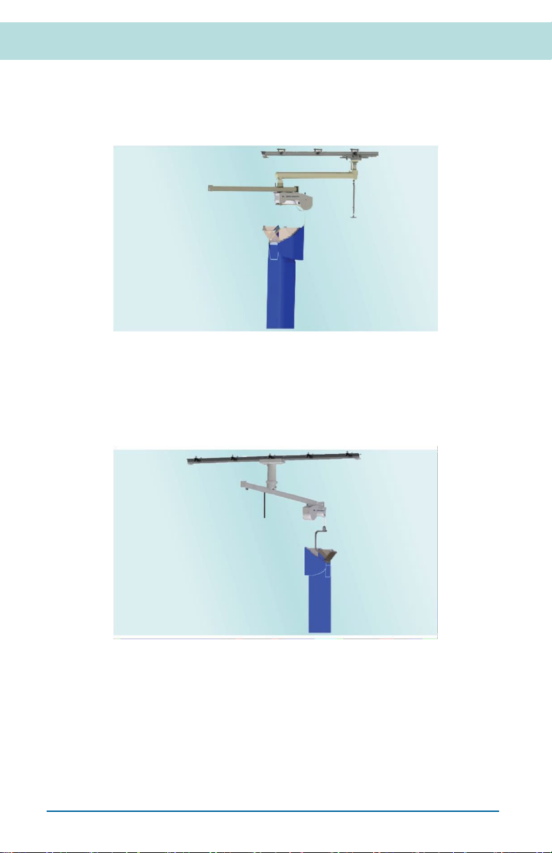
Zero-Gravity Monorail Hinged Swing Arm (ZGCM-HSA)
Features: Ceiling mounted upper track, central pivot on upper trolley with 48” lower
track.
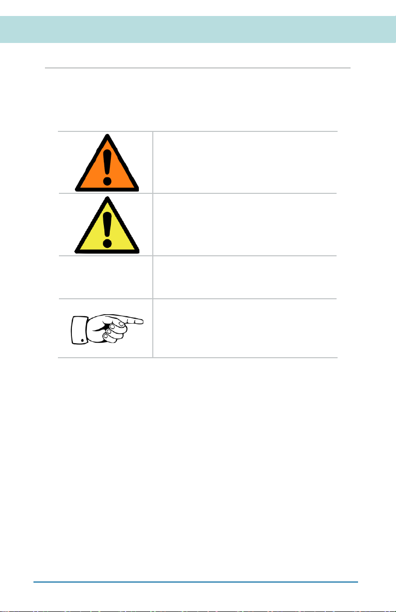
Zero-Gravity Monorail Unit (ZGCM-48 or ZGCM-66)
Features: Ceiling mounted upper track, (ZGCM-48) 48” lower track or (ZGCM-66)
66” lower track.
Zero-Gravity®Radiation Protection System Installation Guide
Floor & Ceiling Mounted Units (83000)
12
Safety Symbols
Important information in this document is marked with symbols and keywords.
Keywords such as WARNING, CAUTION, or ATTENTION indicate the level of risk
involved. The symbols emphasize the message visually.
WARNING!
Indicates a potentially hazardous situation,
which could result in a serious risk of injury or
death to patient or operator and or damage to
equipment or property.
CAUTION!
Indicates a potentially hazardous situation,
which could result in a minor or moderate risk
of injury to patient or operator and or damage
to equipment or property.
ATTENTION!
(Without safety alert symbol)
Indicates a situation that may result in damage
to equipment or property.
NOTE
Useful additional information and tips.
Floor & Ceiling Mounted Units ZGM-6-5H | ZGHSA | ZGCM-48 | ZGCM-66 | ZGCM-HSA
Zero-Gravity®Radiation Protection System Installation Guide 13
Document Safety Symbols
Read and follow all safety instructions in the document and on the device.
WARNING!
To reduce risk of injury, installer(s) must carefully read and
understand this document and be trained prior to use.
WARNING!
The Zero-Gravity ceiling mounting structure must be
customer approved prior to installing Zero-Gravity system.
Failure to have properly designed support structure could
cause structural failure of the ceiling support system and
could result in serious risk of injury or death to patient or
operator and or damage to equipment or property.
WARNING!
The system must be assembled and installed by TIDI
Products authorized representatives. TIDI Products
recommends using a minimum of two persons capable of
lifting 100 pounds (45 kilograms) to install the system.
WARNING! TIP OVER HAZARD
Disassemble device prior to transport. Lower assembly to
lowest height, remove body shield, remove balancer and
remove boom arm.
WARNING! TIP OVER HAZARD
To relocate device in surgical suite: raise leveling feet; roll
over at surfaces with no obstructions.
WARNING! INJURY RISK
Balancer is mounted to a wheeled Trolley and is free to roll.
During assembly, Boom Arm End
Stop Cap is removed and Balancer can easily roll and fall
out of Boom Arm.
Do not leave Balancer unattended while End Stop Cap
is removed.
WARNING! INJURY RISK-CABLE HAZARD
Annual inspections must be performed on the cable. Cables
must be replaced if there are signs of wear.
WARNING! INJURY RISK-CABLE HAZARD
Excessive rotation of Body Shield may cause Balancer
Cable to break. The Body Shield must be lowered and
allowed to unwind after each use, in an unlocked position.
Annual inspections must be performed on the cable. Cables
must be replaced if there are signs of wear.

Zero-Gravity®Radiation Protection System Installation Guide
Floor & Ceiling Mounted Units (83000)
14
WARNING! INJURY RISK
When extending cable from balancer (with body shield not
attached), personnel must maintain control of the spring-
loaded cable at all times. Failure to maintain control of cable
under spring tension can cause serious injury or property
damage.
WARNING! INJURY RISK-BALANCER CABLE
Unlocking balancer lock screw without body shield attached
can cause severe injury. If the body shield is not attached,
the Zero-Gravity balancer cable may rapidly retract in an
uncontrolled manner.
WARNING! RADIATION HAZARD
The Body Shield must be handled with care to avoid
damage to the Body Shield protective lead material. If the
Body Shield is damaged, it must be inspected according to
the Body and Face Shield Fluoroscopy Inspection section of
the User’s Guide
(TIDI Products document 84000).
WARNING! INJURY RISK-HEAVY EQUIPMENT
Use care when handling the Hinged Swing Arm Assembly.
The Support Plate Assembly weighs approximately 200
pounds (90 kilograms) and must be handled using a
mechanical lift.
WARNING! INJURY RISK-HEAVY EQUIPMENT
Use care when handling the Rail Assembly. The Rail
Assembly weighs ~ 150 pounds (68 kilograms) and must be
handled by two or more people.
WARNING! INJURY RISK-HEAVY EQUIPMENT
Use care when handling the Drop Tube. The Drop tube
weighs approximately 140 pounds (64 kilograms). Two or
more people are required for handling.
WARNING! COLLISION RISK
Leaving Lock Pin in disengaged (unlocked ) position,
while operating Boom Arm, may lead to collisions with other
devices in operating room.
CAUTION! INJURY RISK
Failure to maintain control of column, when raising or
lowering, can result in personal injury or property damage.
CAUTION! INJURY RISK
Do not attempt to relocate Floor Unit during a procedure.
Incorrect system positioning or adjustment may cause
personal injury or equipment damage.
Floor & Ceiling Mounted Units ZGM-6-5H | ZGHSA | ZGCM-48 | ZGCM-66 | ZGCM-HSA
Zero-Gravity®Radiation Protection System Installation Guide 15
CAUTION! INJURY RISK
Zero-Gravity oor unit is heavy. Use caution when handling
the device.
Do not release balancer cable unless the clamp stop
is securely fastened and tightened to the body shield
frame.
CAUTION! EQUIPMENT DAMAGE RISK
Do not remove Rail End Stops, allowing the Carriages to
accidentally slide o the Rail. Ball bearings may be lost if
the Carriages are removed.
CAUTION: Heavy Equipment
Use care when handling the Boom Arm assembly. The
Boom Arm assembly weighs ~ 40 pounds (18 kilograms) for
the ZGM-6-5H, ZGHSA, ZGCM-HSA and ZGCM-48, and the
ZGCM-66 weighs ~ 50 pounds (23 kilograms).
Two people are required for handling.
CAUTION! EQUIPMENT DAMAGE RISK
Attempting to adjust the Balancer assembly while the
cable locking screw is locked will cause permanent internal
damage to the Balancer and inability to balance the Body
Shield.
CAUTION! EQUIPMENT DAMAGE RISK
The 66-inch-long Boom has stop screws to limit positioning.
Travel is limited to avoid unsafe loading on the Boom. Do
not remove the travel limiting screws (ZGCM-66 only).
CAUTION! EQUIPMENT DAMAGE RISK
Do not remove and discard protective foam cover on Face
Shield until in-service training.
CAUTION! PINCH POINT HAZARD
Never push or pull Zero-Gravity oor unit by placing hands
on large D-shape plate. Casters may swivel and pinch
hands or ngers. Always use push handles to move Zero-
Gravity system.
CAUTION! PINCH POINT HAZARD
Use care when moving the Carriage along the Rail
Assembly. Fingers or hands can be pinched between the
moving Carriage and the Rail End Stops.
Zero-Gravity®Radiation Protection System Installation Guide
Floor & Ceiling Mounted Units (83000)
16
CAUTION! PINCH POINT HAZARD
Use care when moving the Balancer along the Boom
with the Trolley. Fingers or hands can be pinched
between the moving Trolley and the End Stops.
CAUTION! PINCH POINT HAZARD
Use care when sliding the Boom under the Swivel
Center. Fingers or hands can be pinched between the
Swivel and stop screws or the End Stop Cap in the
top of the Boom.
WARNING! HANDLING PEOPLE HAZARD
Handling people with this equipment can cause
severe injury. Do not use for lifting, lowering or
transporting people.
ATTENTION! Ensure shoulder bolts are tightened securely.
ATTENTION!
Ensure Body Shield assembly is tightly secured in
Balancer Connector and Body Shield is hanging
vertically (not tilted).
ATTENTION! Installation checklists are required as proof of system
operational validation prior to clinical use.
ATTENTION!
Pay strict attention to orientation of the Boom Arm
Assembly in relation to the surgical table.
Orientation arrows MUST be aligned and Table arrows
MUST be pointing to the surgical table.
Zero-Gravity will not function properly if mounted in
the wrong orientation.
GENERAL
Personnel working with Zero-Gravity system(s) must
be properly trained. Repairs or maintenance may only
be performed by TIDI Products representatives or
representatives authorized by TIDI Products.
Floor & Ceiling Mounted Units ZGM-6-5H | ZGHSA | ZGCM-48 | ZGCM-66 | ZGCM-HSA
Zero-Gravity®Radiation Protection System Installation Guide 17
Device Safety Symbols
Important information on the device is marked with symbols and keywords.
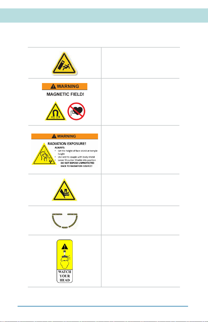
WARNING! TIP OVER HAZARD
Do not lean or hang on boom.
WARNING! MAGNETIC FIELD
HAZARD: CARDIAC DEVICE RISK:
The Zero-Gravity body shield is
magnetically coupled to the Zero-
Gravity vest and may cause a hazard
with user debrillators or pacemakers.
WARNING! RADIATION EXPOSURE
Failure to set body shield at the proper
height, failure to use a vest, failure to
couple vest to body shield, or failure
to lower shoulder shields into position
may cause excess body, cranium
or lens radiation exposure. NEVER
expose unprotected back to radiation
source!
CAUTION! PINCH POINT
Always keep hands and feet clear of
device during operation. Failure to
keep hands and feet clear could result
in serious injury.
ATTENTION! TRIP HAZARD
Low light reective tape strips located
on base help users see and avoid a
trip hazard.
CAUTION! COLLISION RISK
Retract Handle to highest position
when not in use to avoid damage to
equipment and personnel.

READ INSTRUCTIONS FOR USE
To reduce risk of injury, user(s) must
carefully read and understand this
document and be trained prior to use.
CAUTION! RADIATION RISK
To reduce risk of injury, user(s)
must exercise caution to avoid
contamination with or undue exposure
to ionizing radiation.
Zero-Gravity®Radiation Protection System Installation Guide
Floor & Ceiling Mounted Units (83000)
18
Locking Pin is used in adjusting vertical
column height. If Pin is disengaged vertical
column height is adjustable. If Pin is
engaged vertical column height is xed.
Vertical Column Snubber Handle is used
in adjusting vertical column height. Vertical
column height is xed when Handle is
locked. Vertical column height is adjustable
when Handle is unlocked.
Bearing Rotational Lock is used to stop
the boom arm from swinging. If the Boom
Lock is fastened, the Boom Arm is xed
to the vertical column. If the Boom Lock is
unfastened, the boom is free to rotate.
Caster Wheel Lock is used to x the
position of the base on the oor. If the
casters are locked, they will not roll or
swivel. If the casters are unlocked, they will
roll and swivel.
Leveling Feet are used to level the unit for
use and help x it to one location on the
oor. Lower the leveling feet to the ground
to x the unit to one location on the oor.
Raise the leveling feet to move the unit.
Fine adjustments to level the base are also
made using the leveling feet.
Boom Arm Adjustment Knob allows Boom
adjustment relative to the Swivel Center.
If locked the Boom length cannot be
adjusted. If unlocked, the Boom length can
be adjusted.
The Pull Pin Handle allows rotational Boom
adjustment. If locked, the Boom will not
rotate. If unlocked, the Boom will rotate.
Floor & Ceiling Mounted Units ZGM-6-5H | ZGHSA | ZGCM-48 | ZGCM-66 | ZGCM-HSA
Zero-Gravity®Radiation Protection System Installation Guide 19
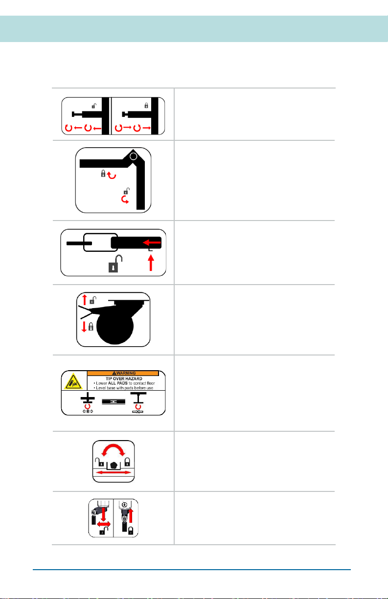
Device Operation Symbols
Important information on the device is marked with symbols and keywords.

Zero-Gravity®Radiation Protection System Installation Guide
Floor & Ceiling Mounted Units (83000)
20
Overhead “Twist and Lock” is used to store
or secure the body shield during storage or
sterile draping. If locked, the Body Shield
is in a xed position. If unlocked, the Body
Shield is free to move.
BODY SHIELD; H; Pb 1.00 (FRONT);
Pb 0.50 (SIDE) / 150 kVp*; MM*
FACE SHIELD; Pb 0.50/150 kVp*
Zero-Gravity Body and Face Shield, P/N ZGBFS
*IEC 61331-3:2014 (NARROW BEAM CONDITIONS)
https://ww w.tidiprodu cts.com/ifu
S/N 123456
TIDI Products, LLC
570 Enterprise Drive
Neenah, WI 54956 USA
P. 1.800.521.1314
P. 1.920.751.4300
www.tidiproducts.com
27U00120 REV 00
ANNEX II,
PPE REGULATION
(EU) 2016/425
2797
0086
ZGBFS-310-000
Body Shield System Label is used to dene
the Body Shield:
• H designates a heavy protective
apron per IEC 61331-3:2014,
Section 5.2
• MM designates an apron sized per
IEC 61331-3:2014, Section 5.2 with
◦A=50.0 inches
(127.0 centimeters)
◦B=23.6 inches
(60.0 centimeters)
◦C=37.4 inches
(95.0 centimeters)
• Front (1.0), side (0.5), and face
shield (0.5) radiation protection in
millimeters of lead equivalent per
150 kVp (Narrow Beam Conditions)
• Standards followed
• Contact information
Shield height label is used to set magnet to
proper body shield height to connect with
vest.
+/- Balancer label shows tightening and
loosening directions for adjusting balancer.
Column height label is used to set preferred
boom height.
Other manuals for Zero-Gravity ZGM-6-5H
1
This manual suits for next models
4
Table of contents
Other TIDI Medical Equipment manuals


