WPG MRTALP4625DC3 User manual

KEEP FOR FUTURE REFERENCE
OPERATING INSTRUCTIONS
MODEL NUMBERS: MRTALP4625DC3,
MRTALP410TDC3
SERIAL NUMBER: ___________
(please see serial label and record number here)
LOW-PROFILE MANUAL ROTATOR / TILTER 600
DC-VOLTAGE, WITH INTELLI-GRIP®TECHNOLOGY
& PAD FRAME T-ARM ASSEMBLIES
(AVAILABLE WITH REMOTE CONTROL SYSTEM)
READ ALL INSTRUCTIONS AND SAFETY RULES
BEFORE OPERATING THIS LIFTER
DESIGNED FOR MATERIALS HANDLING PROFESSIONALS
908 West Main St –P.O. Box 368
Laurel, MT USA 59044
406-628-8231 (phone)
800-548-7341 (phone)
406-628-8354 (fax)


Rev 5.2/9-19 1 MRTALP4-DC3: 35058
TABLE OF CONTENTS
SPECIFICATIONS............................................................................................................ 3
SAFETY............................................................................................................................ 4
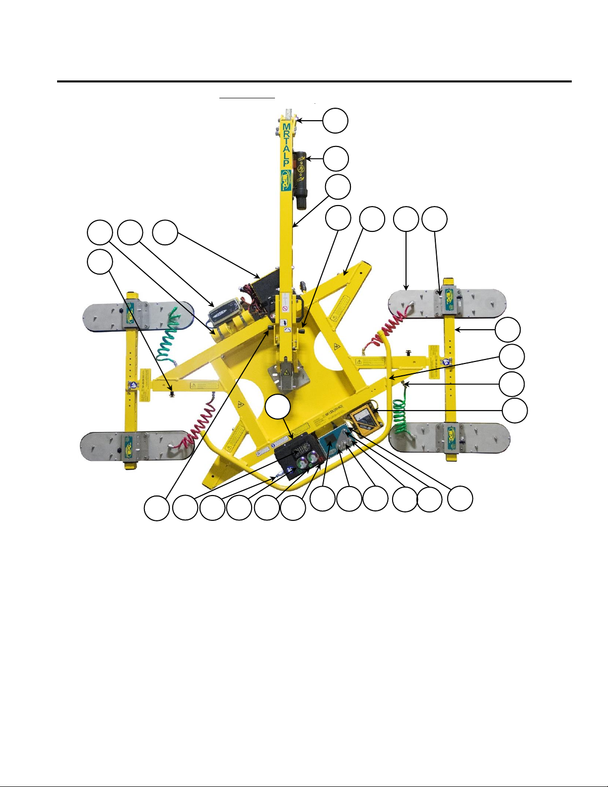
OPERATING FEATURES................................................................................................... 5
ASSEMBLY....................................................................................................................... 6
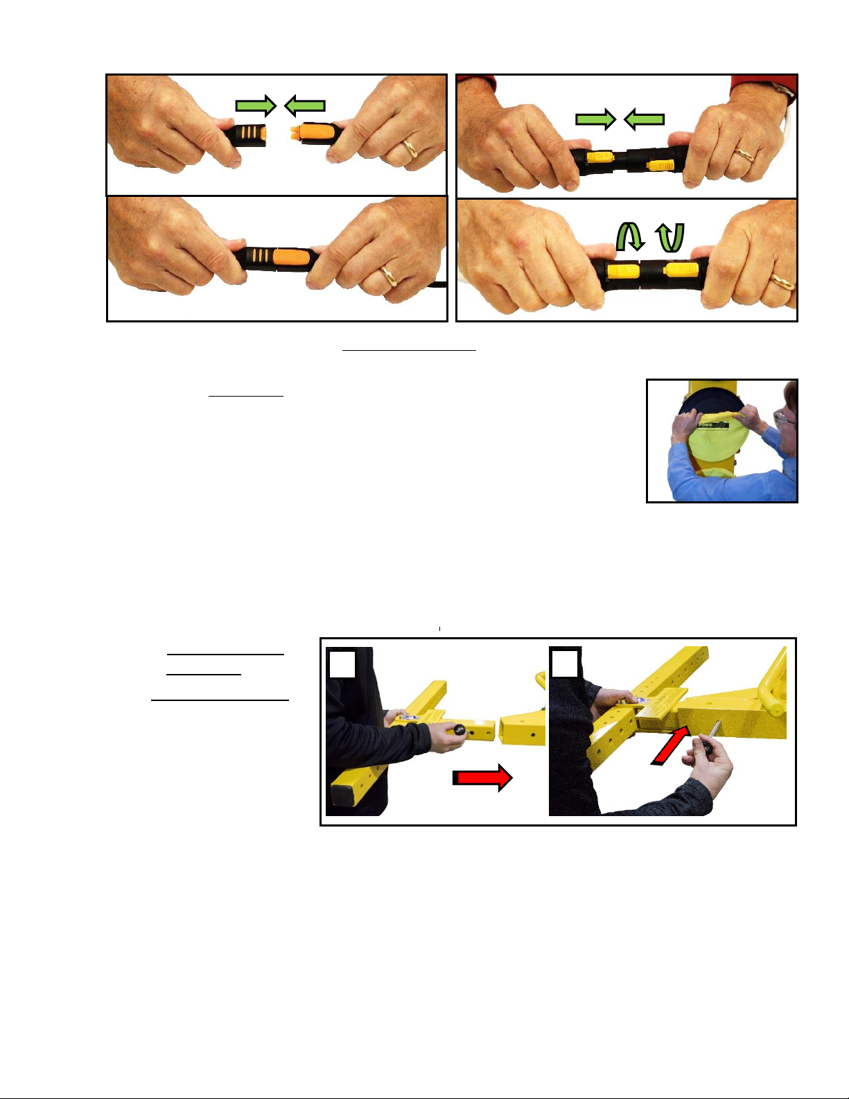
TO INSTALL/REMOVE T-ARM ASSEMBLIES ....................................................................................7
TO INSTALL/REMOVE VACUUM PADS ............................................................................................ 8
TO POSITION VACUUM PADS ....................................................................................................... 8
TO REPOSITION THE T-ARM CROSS MEMBERS ...............................................................................8
Connecting/Disconnecting Vacuum Hoses...............................................................................................................................9
INTENDED USE ............................................................................................................. 10
LOAD CHARACTERISTICS .......................................................................................................... 10
OPERATING ENVIRONMENT .......................................................................................................10
DISPOSAL OF THE LIFTER..........................................................................................................11
OPERATION .................................................................................................................. 12
BEFORE USING THE LIFTER .......................................................................................................12
Taking Safety Precautions ..................................................................................................................................................... 12
Selecting a Screen Language ..................................................................................................................................................12
Performing Inspections and Tests ..........................................................................................................................................13
Preparing to Use the Remote Control System ...................................................................................................................... 13
TO ATTACH THE PADS TO A LOAD ...............................................................................................14
Positioning the Lifter on the Load ..........................................................................................................................................14
Powering up the Lifter............................................................................................................................................................15
Sealing the Pads on the Load .................................................................................................................................................16
Reading the Vacuum Gauges..................................................................................................................................................16
Vacuum Level on Optimal Surfaces ........................................................................................................................................17
Vacuum Level on Other Surfaces ...........................................................................................................................................17
TO LIFT AND MOVE THE LOAD.................................................................................................... 18
About the Tilt Linkage ............................................................................................................................................................18
Interpreting the Lift Light .......................................................................................................................................................18
Watching Vacuum Indicators ................................................................................................................................................. 18
Controlling the Lifter and Load...............................................................................................................................................19
In Case of Power Failure.........................................................................................................................................................19
TO ROTATE THE LOAD ..............................................................................................................20
TO TILT THE LOAD ...................................................................................................................21
TO RELEASE THE PADS FROM THE LOAD....................................................................................... 22
AFTER USING THE LIFTER ......................................................................................................... 23
Storing the Lifter.....................................................................................................................................................................23

Rev 5.2/9-19 2 MRTALP4-DC3: 35058
MAINTENANCE ............................................................................................................. 24
INTELLI-GRIP®DIAGNOSTIC CODES...........................................................................................24
INSPECTION SCHEDULE ............................................................................................................28
Infrequent Use ....................................................................................................................................................................... 29
TESTING ................................................................................................................................30
Operational Tests................................................................................................................................................................... 30
Load Test................................................................................................................................................................................ 30
12-VOLT BATTERY ASSESSMENT ................................................................................................30
12-VOLT BATTERY RECHARGE ...................................................................................................31
NOTIFICATION BUZZER BATTERY TEST ........................................................................................31
VACUUM PAD MAINTENANCE .....................................................................................................32
Pad-to-Load Friction Coefficient ............................................................................................................................................ 32
Pad Inspection........................................................................................................................................................................ 32
Pad Cleaning........................................................................................................................................................................... 32
VACUUM TEST .........................................................................................................................33
REMOTE CONTROL SYSTEM TEST ................................................................................................33
TO REPLACE SEALING RING IN VPFS10T PADS ...........................................................................34
TO REPLACE PAD INSERTS IN VPFS625 PADS .............................................................................35
REPLACEMENT PARTS LIST .......................................................................................... 37
LIMITED WARRANTY.................................................................................................... 38

Rev 5.2/9-19 3 MRTALP4-DC3: 35058
SPECIFICATIONS
!!–CE–!! This symbol appears only when a CE Standard is
different
from other applicable standards. CE requirements are
mandatory in the European Union, but may be optional elsewhere.
1
Standard with replaceable pad inserts for rough or textured surfaces (see REPLACEMENTS PARTS).
2
Standard with replaceable sealing rings for rough or textured surfaces (see REPLACEMENT PARTS).
3
The Maximum Load Capacity is rated at a vacuum of 16" Hg [-54 kPa] on clean, smooth, nonporous flat surfaces with a friction
coefficient of 1. Pad compound, load rigidity, strength, surface conditions, overhang, angle, center of gravity and temperature can
also affect the lifting capacity. A qualified person should evaluate the effective lifting capacity for each use.
4
Vacuum pads, filter elements and other wear-out items are excluded.
Description:
Designed for use with hoisting equipment, MRTALP4-DC3 lifters use vacuum to support loads,
as well as manual 180° rotation and mechanically assisted, manual 90° tilt to position loads.
Model Number:
MRTALP4625DC3
MRTALP410TDC3
Vacuum Pads:
6" x 25" [15 cm x 64 cm] nominal dimensions,
(Model VPFS625)1
10" [25 cm] nominal diameter,
(Model VPFS10T)2
(Four each, standard rubber)
Pad Spread:
---------------------------- (to outer edges) ----------------------------
Maximum:
37" x 92½" [94 cm x 235 cm]
45¾" x 78¾" [116 cm x 200 cm]
Minimum:
20" x 92½" [51 cm x 235 cm]
25¾" x 78¾" [65 cm x 200 cm]
Lifter Weight:
250 lbs [114 kg]
201 lbs [92 kg]
Maximum Load Capacity:3
600 lbs [270 kg]
Per-Pad:
150 lbs [68 kg]
Power System:
12 volts DC, 5 amps
Battery Operating Time:
18 amp-hours
Rotation Capability:
Manual, 180°, with latching at every 30° of revolution (when desired)
Tilt Capability:
Manual, 90°, with four-bar tilt linkage that provides mechanical advantage and automatic
latching in upright position
Options:
Available
with Remote Control System –FCC, CE, and ICC certified.
Available
with Pad Frame Extension Arms and Pad Frame Rocker Arms for installing roof panels.
See separate instructions about these and other options.
Maximum Operating
Elevation:
6,000' [1,828 m]
Operating
Temperatures:
32° to 104° F [0° to 40° C]
Service Life:
20,000 lifting cycles, when used and maintained as intended4
Software Version:
Intelli-Grip®7.0‒7.6
ASME Standard BTH-1:
Design Category "B", Service Class "0" (see www.wpg.com for more information)

Rev 5.2/9-19 4 MRTALP4-DC3: 35058
SAFETY
Wear personal protective equipment that is appropriate for the load material. Follow trade
association guidelines.
Use the lifter only in an approved OPERATING ENVIRONMENT (see INTENDED USE).
Do not use a lifter that is damaged, malfunctioning, or missing parts.
Do not use a lifter if the sealing edge of any vacuum pad is cut or otherwise damaged.
Do not remove or obscure safety labels.
Do not use a lifter if the Maximum Load Capacity or any safety label appears to be
missing or obscured.
Make sure the contact surfaces of the load and vacuum pads are clean before attaching
the lifter (see MAINTENANCE).
Do not exceed the Maximum Load Capacity or lift loads the lifter is not designed for
(see INTENDED USE).
Do not lift cracked or broken glass.
Position the vacuum pads correctly on the load before lifting (see OPERATION).
Do not lift a load if any vacuum indicator shows inadequate vacuum (see OPERATION).
Do not touch the vacuum release controls during a lift.
Do not allow people to ride on the lifter or the load.
Do not lift a load higher than necessary or leave suspended loads unattended.
Do not position a loaded or unloaded lifter over people.
Keep unauthorized personnel away from the lifter, to avoid injury in case of an unintended
load release.
Before servicing the lifter, place the power control in the inactive position and, when
possible, disconnect the power source (only applicable to powered lifters).
Do not make any modifications to the lifter (see LIMITED WARRANTY).

Rev 5.2/9-19 5 MRTALP4-DC3: 35058
OPERATING FEATURES
Features shown here are underlined on their first appearance in each section following.
1 LIFT POINT
11 RADIO RECEIVER (optional)
21 AIR FILTERS
2 INSTRUCTIONS CANISTER
12 INTELLI-GRIP®CONTROL UNIT
22 STROBE LIGHT
3 LIFT BAR
13 “POWER” BUTTON
23 TILT RELEASE LEVER
4 ROTATION RELEASE LEVER
14 “RELEASE”BUTTON
24 COTTERLESS HITCH PIN
5 PAD FRAME
15 “ATTACH” BUTTON
25 VACUUM RESERVE TANKS
6 VACUUM PAD
16 “FUNCTION” BUTTON
26 BATTERY CHARGER
7 SLIDING/MOVABLE PAD MOUNT
17 LCD SCREEN with BATTERY GAUGE
27 BATTERY
8 PAD FRAME T-ARM ASSEMBLY
18 NOTIFICATION BUZZER
28 Cover for VACUUM PUMP,
9 CONTROL HANDLE
19 VACUUM LIFT LIGHT
CIRCUIT BOARD and
10 QUICK CONNECTOR
20 VACUUM GAUGES
VACUUM SENSORS
Note: Although some of the following photos do not show this specific lifter,
they all illustrate how this kind of lifter functions.
19
20
21
22
18
12
13
14
15
16
17
8
9
10
11
1
2
3
5
6
7
4
23
25
26
27
24
28

Rev 5.2/9-19 6 MRTALP4-DC3: 35058
ASSEMBLY
1) Remove all vacuum lifter restraints and save them with the shipping container for future use.
2) If necessary, assemble the lift bar as shown. Tighten both bolts (2)
securely.
3) Adjust the lift point to optimize the lifter's hang angle:
3.1) Remove the retaining bolt (3) and loosen the pivot bolt (4).
3.2) Move the lift point to the appropriate position.
3.3) Reinstall the retaining bolt and tighten both bolts securely.
Note: Position the lift point to avoid contact with long configurations
of the pad frame during rotation.
4) Suspend the lifter from appropriate hoisting equipment:
4.1) Select a crane and/or hoist rated for the
Maximum Load Capacity plus the Lifter Weight.
Note: Any lifter use must comply with all statutory or regulatory
standards for hoisting equipment in your region.
4.2) Disengage the tilt latch and
raise the lift bar.
4.3) Attach the hoisting hook to the lift point.
Make sure hook has
restraining latch
(circled).
Note: Make sure the hook does
not interfere with the load,
using rigging as needed.
Only use rigging rated for
Maximum Load Capacity
plus Lifter Weight.
4.4) Use the hoisting equipment to remove the lifter from the shipping container. Avoid
damaging the vacuum pads.

Rev 5.2/9-19 7 MRTALP4-DC3: 35058
5) Connect the electrical connectors.
Install the 9-volt battery for the notification buzzer as directed in the NOTIFICATION BUZZER
BATTERY TEST (see MAINTENANCE).
6) Assemble the pad frame for optimal load support (see next section).
Remove the pad covers and save them for future use (if applicable).
7) Before you place the lifter in service, perform Operational and Load Tests (see
MAINTENANCE).
TO INSTALL/REMOVE T-ARM ASSEMBLIES
1) Insert a T-arm assembly
into the pad frame.
2) Use a cotterless hitch pin
to secure the T-arm.
3) Install the second T-arm
assembly likewise.
Note: Always position T-arms
as shown in OPERATING
FEATURES.
To remove the T-arm assemblies, reverse these steps. Store removed components in a clean, dry
location.
1
2

Rev 5.2/9-19 8 MRTALP4-DC3: 35058
TO INSTALL/REMOVE VACUUM PADS
1) Position a sliding/movable
pad mount on the T-arm
assembly.
2) Use the cotterless hitch pin
to secure the pad mount.
3) Install the other pad mounts
likewise.
Notes: Use only 2 pads on each
T-arm assembly. Pads must be
arranged symmetrically, to keep the lifter balanced.
To remove vacuum pads, reverse these steps. Store removed components in a clean, dry
location.
TO POSITION VACUUM PADS
1) Remove the cotterless hitch pin that secures a sliding/movable pad mount to the pad frame.
2) Position the pad mount as required on the T-arm assembly.
3) Use the cotterless hitch pin to secure the pad mount.
4) Repeat these steps to position other pad mounts as needed.
Note: Use only 2 pads on each T-arm assembly. Pads must be arranged symmetrically, to keep
the lifter balanced.
TO REPOSITION THE T-ARM CROSS MEMBERS
To adjust the pad alignment more precisely, reposition the cross members of the T-arm
assemblies:
1) Remove the bolts connecting a cross member.
2) Move the cross member to the appropriate position.
3) Reinstall the bolts and tighten them securely.
4) Repeat these steps to reposition the other cross member.
1
2
1
2
3

Rev 5.2/9-19 9 MRTALP4-DC3: 35058
Connecting/Disconnecting Vacuum Hoses
•To connect a vacuum hose, push the male and female ends of
the quick connector together until they lock.
Make sure quick connectors seal completely and
all vacuum hoses function correctly.
•To disconnect the vacuum hose, move the release ring on the
female end until the quick connector separates.
Make sure the hoses are
connected correctly
(green to circuit “1” and
red to circuit “2”).
Note: The 2 vacuum circuits correspond with their
matching vacuum gauges.

Rev 5.2/9-19 10 MRTALP4-DC3: 35058
INTENDED USE
LOAD CHARACTERISTICS
Do NOT lift explosives, radioactive substances or other hazardous materials.
Make sure the vacuum lifter is intended to handle each load, according to these requirements:
• The load weight must not exceed the Maximum Load Capacity.
• The load must be a single piece of relatively nonporous material with a flat and relatively
smooth contact surface. Flexible sealing rings can accommodate some surface relief, provided
contour changes are not too abrupt. To determine whether the load is too porous or rough,
perform a Load Suitability Test as directed in To Attach the Pads to a Load (see OPERATION).
• The load's contact surface must be able to obtain a friction coefficient of 1 with the lifter's
vacuum pads, or capacity should be derated appropriately (see MAINTENANCE).
• The load's surface temperature must not exceed the Operating Temperatures.
5
• The load's
minimum
length and width are determined by the Pad Spread (see
SPECIFICATIONS).
• The load's
maximum
length and width are determined by the allowable overhang.
6
• 8" [20 cm] is the allowable thickness of loads at the Maximum Load Capacity.
7
Note: Standard vacuum pads can stain or deform load surfaces with light colors or soft
coatings. Test such surfaces for damaging effects before using the lifter on them.
8
OPERATING ENVIRONMENT
Make sure the vacuum lifter is intended for use in each work environment, given the following
restrictions:
Never use lifter in dangerous environments.
• This lifter is not intended for any environment that is dangerous to the operator or damaging to
the lifter. Avoid environments containing explosives, caustic chemicals and other dangerous
substances.
5
Vacuum pads made from a heat-resistant rubber compound can enable you to lift loads with higher surface temperatures.
Contact Wood’s Powr-Grip or an authorized dealer for more information.
6
The allowable overhang is the amount of load material that can extend sideways beyond the vacuum pads without breaking or
otherwise being damaged. This depends on the load material, its thickness, and the angle of handling (if any). Since every
material has different physical properties, the allowable overhang must be evaluated separately for each load type. Contact
Wood’s Powr-Grip or an authorized dealer for more information.
7
However, the allowable thickness increases as load weight decreases. Contact Wood’s Powr-Grip for more information.
8
Alternative rubber compounds are available for these purposes. Contact Wood’s Powr-Grip or an authorized dealer for more
information.

Rev 5.2/9-19 11 MRTALP4-DC3: 35058
• The work environment is limited by the Maximum Operating Elevation and
Operating Temperatures.
Metal particles and similar environmental contaminates could result in vacuum
pump failure.
• The lifter is not designed to be watertight: Do not submerge the lifter or use it in unsuitable
weather.
By reducing slip resistance of vacuum pads, moisture can result in reduced
lifting capacity.
DISPOSAL OF THE LIFTER
After the Service Life of the vacuum lifter has ended (see SPECIFICATIONS), dispose of it in
compliance with all local codes and applicable regulatory standards.
Note: Special disposal regulations may apply to the battery.

Rev 5.2/9-19 12 MRTALP4-DC3: 35058
OPERATION
BEFORE USING THE LIFTER
Determine whether the vacuum lifter is capable of each intended task (see SPECIFICATIONS and
INTENDED USE). Then complete the following preparations:
Taking Safety Precautions
Read all directions and safety rules before using lifter.
• Be trained in all industry and regulatory standards for lifter operation in your region.
Always wear appropriate personal protective equipment.
• Follow trade association guidelines about precautions needed for each load material.
Selecting a Screen Language
When the lifter is powered up for the first time, the Intelli-Grip®
Control Unit prompts the operator to select a language for the
LCD screen.
To scroll down, press the “release”
button ( ).
To scroll up, press the “attach” button ( ).
To select a language, press the “function” button ( ).
9
Note: A similar process is used to navigate all menus.
9
To change the language again, refer to the INTELLI-GRIP®OPERATOR MENUS section of the
SERVICE MANUAL
.

Rev 5.2/9-19 13 MRTALP4-DC3: 35058
Performing Inspections and Tests
Always check battery energy before using lifter
(see MAINTENANCE).
• Follow the INSPECTION SCHEDULE and TESTING (see
MAINTENANCE).
• Always perform a VACUUM TEST before placing a lifter in service
(see MAINTENANCE).
•
Examine air filters regularly and service when needed.
Service the 2 air filters whenever a bowl contains liquid or other contaminates, or an element
appears dirty (see AIR FILTER MAINTENANCE in
SERVICE MANUAL
).
Make sure notification buzzer can be heard over noise at
operator position.
• Make sure the notification buzzer is clearly audible at the maximum distance
between the operator and the lifter, despite any barriers or obstacles.
10
The
VACUUM TEST provides a convenient opportunity to check this (see
MAINTENANCE).
Preparing to Use the Remote Control System
This optional radio receiver and radio transmitter enable
you to activate the lifter's “attach” and “release” functions
at distances up to 250' [76 m], provided you have a clear and
direct view of the lifter and its status indicators.
To operate a lifter remotely, follow these safety rules:
• Visually verify the status of the lifter and load before lifting.
Make sure nearby personnel are aware of intended
remote control actions.
• Monitor the lifter at all times to make sure it is functioning as
intended.
11
• Be sure the load is landed and supported correctly before
releasing it (see following sections).
Note: To prevent any radio transmission, press the emergency
transmitter disconnect button.
12
10
Maximum buzzer volume is 95 dBA at 2' [60 cm]. If applicable, consult EN 7731 to make sure the notification buzzer complies
with CE Standards.
11
The Remote Control System is designed to prevent multiple lifters from responding. Nevertheless, radio controlled lifters should
be tested to make sure each transmitter controls only one lifter.
12
To reset the emergency disconnect, twist the button clockwise and allow it to spring outward to its original position.
1 EMERGENCY TRANSMITTER DISCONNECT
2 TRANSMISSION INDICATOR LIGHT
3 “RELEASE” BUTTON
4 TRANSMITTER POWER/“FUNCTION” BUTTON
5 “ATTACH” BUTTON
2
5
4
3
1

Rev 5.2/9-19 14 MRTALP4-DC3: 35058
TO ATTACH THE PADS TO A LOAD
Positioning the Lifter on the Load
1) Make sure that the contact surfaces of the load and the
vacuum pads are clean (see MAINTENANCE).
Attach lifter to load as directed below. Failure to
follow instructions can result in load damage
or personal injury.
2) Attach the lifter to the load “on center” or “above center”, as required:
●To rotate and tilt loads normally, center the pad frame on the load (“on center”).
13
●To tilt loads lengthwise from the flat to upright orientation, center the
pad frame from left to right on the load, and position the vacuum pads
toward what will be the top end when upright (“above center”). The
load will automatically tilt to the upright position when lifted.
3) Make sure all vacuum pads will fit on the load and will be loaded
evenly. When applicable, consult the Per-Pad Load Capacity.
4) Place the vacuum pads in contact with the load surface.
13
The lifter is designed to handle the maximum load weight when the load’s center of gravity is positioned within 2" [5 cm] of
the lifter’s rotation axis. Off-center loads may rotate or tilt unexpectedly.
On Center
Above Center

Rev 5.2/9-19 15 MRTALP4-DC3: 35058
Powering up the Lifter
Press the lifter's power button ( ).
The vacuum pump will run for a few seconds, as a normal
function of the Intelli-Grip®self-diagnostics.
To use the Remote Control System, hold the transmitter
power button ( ) briefly to activate the radio
transmitter.
14
Note: When you hold any button on the transmitter, the
transmission indicator light flashes green if the transmitter is
activated or red if it is not activated.
14
The radio transmitter turns off automatically, after a period of inactivity.

Rev 5.2/9-19 16 MRTALP4-DC3: 35058
Sealing the Pads on the Load
Press the “attach” button ( ) on the lifter.
Keep “attach” function activated throughout lift.
To use the Remote Control System, press the “attach”
button ( ) on the radio transmitter.
The vacuum pump will run until the vacuum pads seal completely. If the lifter takes too long to
attach, the notification buzzer chirps and the LCD screen displays “Vacuum not increasing
normally”, along with a diagnostic code (see MAINTENANCE). In this case, press the lifter firmly
against the load to help the pads begin to seal.
15
Reading the Vacuum Gauges
Two vacuum gauges show the current
vacuum level in positive inches of Hg and
negative kPa for the dual vacuum system:
•
Green
range: Vacuum level is sufficient to
lift the maximum load weight (figure B1).
•
Red
range: Vacuum level is
not
sufficient to
lift the maximum load weight (figure B2).
If it takes more than 5 seconds for the
vacuum level to reach 5" Hg [-17 kPa] on
either vacuum gauge, press on any vacuum
pad that has not yet sealed.
15
Although a vacuum pad may become distorted during shipping or storage, this condition should correct itself with continued
use.
B2
B1

Rev 5.2/9-19 17 MRTALP4-DC3: 35058
Vacuum Level on Optimal Surfaces
When the lifter is attached to
clean, smooth, nonporous
surfaces, it should be able to maintain
sufficient vacuum for lifting, except when used above the Maximum Operating Elevation.
If it does not, check for faults in the vacuum generating system (see MAINTENANCE:
VACUUM TEST).
Vacuum Level on Other Surfaces
When the lifter is attached to
contaminated, rough or porous
surfaces, it may not be able to
maintain sufficient vacuum for lifting, due to leakage at the vacuum pads.
16
In this case:
•Thoroughly clean the load surface and the vacuum pads (see MAINTENANCE).
•When necessary, perform a Load Suitability Test:
1) Make sure the vacuum generating system is functioning correctly (see MAINTENANCE).
2) Attach the vacuum pads to the load as previously directed.
3) After the vacuum pump stops running, hold the “function” button ( ) and the “power”
button ( ) for at least 5 seconds to power down the lifter.
Note: During this time the LCD screen displays “WARNING! Is load attached?”, the notification
buzzer chirps rapidly and the strobe light flashes.
4) Raise the load a minimal distance, to make sure it is supported by the lifter.
Take precautions in case load should fall during test.
5) Watch each vacuum gauge for 5 minutes:
The lifter must maintain a minimum vacuum
level of 10" Hg [-34 kPa].
If not, the load is not suitable for this lifter.
17
6) Lower the load after 5 minutes or whenever the vacuum level is less than 10" Hg [-34 kPa].
16
Contaminated loads can also cause the vacuum pump to run frequently or continuously. Since excessive pumping quickly
reduces battery energy, clean the load whenever possible.
17
Certain load materials are too rough or porous to pass this test. However, where CE Standards do not apply, the lifter may be
allowed to lift such loads. Contact Wood’s Powr-Grip for more information.

Rev 5.2/9-19 18 MRTALP4-DC3: 35058
TO LIFT AND MOVE THE LOAD
Lift bar must be vertical to lift load.
About the Tilt Linkage
Unbalanced loads may tilt unexpectedly during lifter operation.
The tilt linkage minimizes operator effort and automatically holds a balanced load in either the
upright or the flat position. However, an unbalanced load may tilt unexpectedly, resulting in load
damage or personal injury.
Make sure load is positioned correctly on lifter.
To minimize these risks, make sure
before lifting any load
that it has appropriate LOAD
CHARACTERISTICS (see INTENDED USE) and is attached correctly to the lifter as previously directed.
Interpreting the Lift Light
When the vacuum lifter is ready to lift the Maximum Load Capacity, the
vacuum lift light turns
on
automatically and the vacuum pump turns
off
temporarily, to conserve battery energy.
Never lift load unless lift light is illuminated, because premature
lifting could result in load release and personal injury.
Watching Vacuum Indicators
Watch the vacuum lift light and both vacuum gauges throughout the entire lift.
Make sure vacuum indicators remain
completely visible.
The vacuum pump turns on and off to overcome
any leakage. However, if the leak rate is greater
than normal, the notification buzzer chirps and
the LCD screen displays “Vacuum decrease on
circuit #”, along with a diagnostic code.
18
Such
leaks can cause the battery to be discharged
more quickly, reducing the lifter's operating time.
To prevent this, review the section TO ATTACH THE
PADS TO A LOAD: Vacuum Level on Other Surfaces.
If the vacuum level decreases to less than 16" Hg [-54 kPa] on either gauge, the notification
buzzer sounds continuously, the lift light turns off, and the LCD screen displays “INSUFFICIENT
VACUUM!”, along with a diagnostic code (see MAINTENANCE). If this happens:
1) Keep everyone away from a suspended load until it can be safely lowered to a stable support.
Stay clear of any suspended load while indicators warn of low vacuum.
18
Automatic leak detection is
not
a substitute for performing the VACUUM TEST, as required by the INSPECTION SCHEDULE and
TESTING (see MAINTENANCE).
Other manuals for MRTALP4625DC3
3
This manual suits for next models
1
Table of contents
Other WPG Industrial Equipment manuals