AB
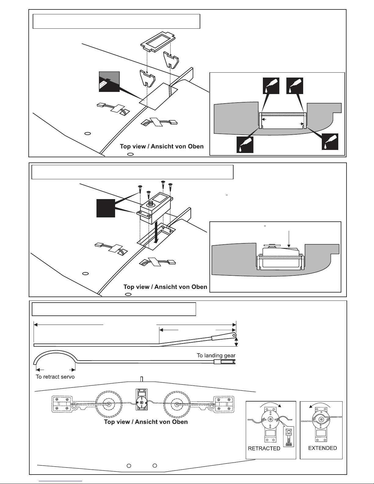
Plastic control horn
...................3
2x12mm screw
...............6
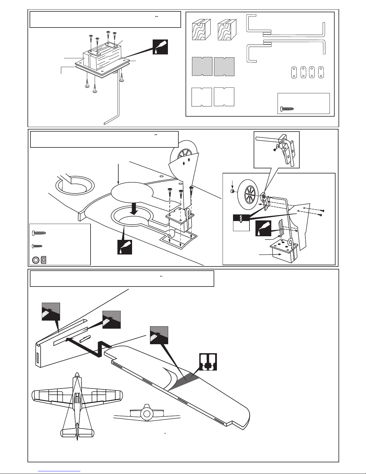
Apply the epoxy
both side
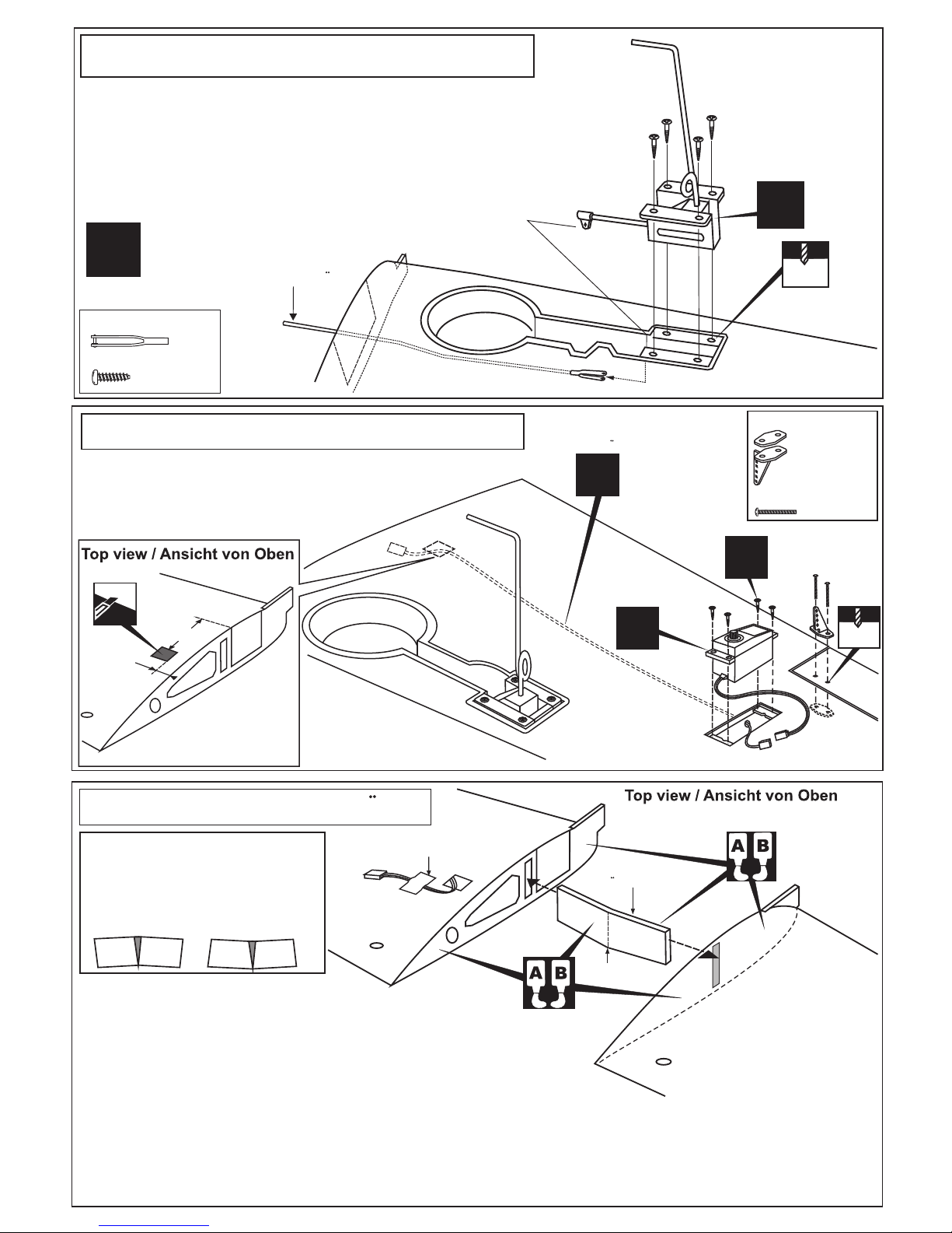
1-Trial fit the vertical stabilizer in place . Check the alignment of the
vertical stabilizer. When you are satisfied with the alignment, use a
pencil to trace around the right and left of the stabilizer where it
meets the fuselage.
2-Remove the vertical stabilizer from the fuselage. Using the sharp
hobby knife, carefully cut away the covering inside the lines which
were marked above.
3-Spread epoxy (30 minute) onto the right and left and bottom of the
vertical stabilizer along the area where the covering was removed
and to the fuselage where the vertical stabilizer mounts.
4-Install the vertical stabilizer into the fuselage and adust the align-
ment as described in steep 1.l
Allow the epoxy to cure before proceeding to next step.
10- Vertical stabilizer / Hohenleitwerk
Cut away only
the covering
both side*
BB’
AB
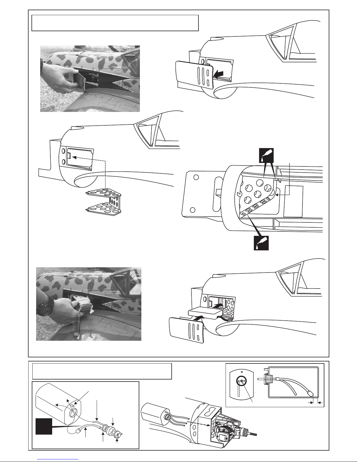
Apply a thin layer of machine oil or petroleum jelly to only the pivot point of
the hinges on the elevator, then push the elevator and its hinges into the
hinge slots in the trailing edge of the horizontal stabilizer. There should be a
minimal hinge gap and the end of the elevator should not rub against the
horizontal stabilizer.
When satisfied with the and alignment, hinge the elevator to the horizontal
stabilizer using 5 minute epoxy. Make sure to apply a thin layer of epoxy to
the top and bottom of both hinges and to inside the hinge slots. Repeat the
previous procedures to hinge the second elevator to the other side of the
horizontal stabilizer.
12- Control horn / Ruderhorn
3/8” (10mm)
2x12mm screw
B=B’
Securely glue together. If coming off during flight, you lose
control of your air plane!
Vergewissern Sie sich, sauber geklebtzu haben. Andernfalls
konnen Probleme mit der Flugeigenschaft auftreten!
Securely glue together. If coming off during flight, you lose control of
your air plane!
11- Elevator / Hohenruder
2mm
2mm
5O5O
2x12mm Blechschraube
Ansicht von unten
Bottom view
* WARNING: When removing any covering from the airframe,
please ensure that you secure the cut edge with CA or similar
cement. This will ensure the covering remain tight.
Hinge STABILIZER
Apply thin CA
both the top and
bottom.
CA
CA