Timespace X300 Series User manual

Timespace Technology Ltd Blackstone Road Huntingdon Cambridgeshire PE29 6TT UK
®
X300
Instruction Manual
Designed and Manufactured in the UK
The latest version of the X300 Manual is available online; www.tspace.co.uk
X200 Operating Software V2.0.1
X300 Operating Software V1.3.2
V400 Operating Software V1.2.3
PCLink Suite V7.5
PCLink200 V1.8.2
PCPlayer V1.8.2
RemoteLink V1.8.2
X-Communicate V1.8.2
Kstation V1.0.0.4
SafetyLink V1.0
ImageLink V1.0
LANLink V4.0
© 30th April 2015

2
Contents
SAFETY..................................................................................................................................................... 5
ENVIRONMENTAL ................................................................................................................................... 5
SHOCK AND VIBRATION..................................................................................................................... 5
EMC....................................................................................................................................................... 5
CONFORMITY ...................................................................................................................................... 5
RECYCLING.......................................................................................................................................... 5
EC DECLARATION OF CONFORMITY ............................................................................................... 6
E11 TYPE APPROVAL ......................................................................................................................... 7
SYSTEM OVERVIEW ............................................................................................................................. 10
X300 Front Panel ................................................................................................................................ 11
SD Card Compatibility......................................................................................................................... 11
X300 Rear panel, common connections ............................................................................................. 13
X300-4 Rear Panel.............................................................................................................................. 15
X300-16 Rear Panel............................................................................................................................ 16
X300 DIGITAL RECORDER ................................................................................................................... 18
INSTALLATION................................................................................................................................... 19
T408 VEHICLE KIT ............................................................................................................................. 20
SERVICE AND FAIL LED ................................................................................................................... 25
PROGRAMMING................................................................................................................................. 26
HELP SCREENS................................................................................................................................. 26
SOFTWARE UPDATES...................................................................................................................... 26
SOFTWARE UPDATES - PCLink....................................................................................................... 27
LANGUAGE SELECTION................................................................................................................... 28
VIDEO STANDARD - PAL / NTSC...................................................................................................... 28
FILE SYSTEM..................................................................................................................................... 28
VIDEO COMPRESSION ..................................................................................................................... 29
AUDIO................................................................................................................................................. 30
PC ACCESS PRECAUTIONS............................................................................................................. 31
PC NETWORK ACCESS .................................................................................................................... 31
WATERMARK..................................................................................................................................... 32
SEQUENCING .................................................................................................................................... 32
WATERMARK FILE ............................................................................................................................ 32
GPS..................................................................................................................................................... 33
REMOTE OPERATION (GSM / LAN / Wifi / 3G)................................................................................ 34
RS232 EXTERNAL CONTROL........................................................................................................... 36
X300 MENU SYSTEM............................................................................................................................. 42
MAIN MENU........................................................................................................................................ 43
NORMAL RECORDING...................................................................................................................... 44

3
ALARM RECORDING......................................................................................................................... 46
ALARM INPUTS.................................................................................................................................. 47
ALARM OUTPUT ................................................................................................................................ 48
ALARM CYCLER................................................................................................................................. 49
SD CARD ............................................................................................................................................ 50
SD CARD RECORDING..................................................................................................................... 51
SD CARD FILE COPY ........................................................................................................................ 52
SHOT RECORDING ........................................................................................................................... 53
MOTION DETECTION........................................................................................................................ 54
PRE-MOTION RATE RECORDING.................................................................................................... 55
AUDIO RECORDING.......................................................................................................................... 55
RECORDED FILES............................................................................................................................. 57
VIDEO OUTPUT.................................................................................................................................. 58
MAIN VIDEO SWITCHER................................................................................................................... 58
AUX VIDEO SWITCHER..................................................................................................................... 59
TIME AND DATE................................................................................................................................. 60
CAMERA SETTINGS.......................................................................................................................... 61
FILE SYSTEM..................................................................................................................................... 62
SYSTEM INFO.................................................................................................................................... 63
PASSWORD........................................................................................................................................ 64
POWER OPTIONS.............................................................................................................................. 65
RESET................................................................................................................................................. 66
EXTERNAL EQUIPMENT................................................................................................................... 67
LAN...................................................................................................................................................... 68
GPS..................................................................................................................................................... 69
GSENSOR........................................................................................................................................... 70
GSM / REMOTE.................................................................................................................................. 71
SMS MESSAGES ............................................................................................................................... 72
HEALTH OVER SMS .......................................................................................................................... 73
IMAGES OVER SMS .......................................................................................................................... 74
PTZ...................................................................................................................................................... 75
SMTP EMAIL....................................................................................................................................... 76
WEB SERVER..................................................................................................................................... 77
ADVANCED......................................................................................................................................... 78
LOAD SYSTEM UPGRADE................................................................................................................ 80
TIMESPACE REVIEWER ....................................................................................................................... 81
FUNCTION...................................................................................................................................... 81
MENU NAVIGATION CONTROLS.................................................................................................. 82
PLAYBACK & RECORDING........................................................................................................... 83

4
CAMERA SWITCHER..................................................................................................................... 84
PTZ CONTROLS............................................................................................................................. 85
SETTING PTZ PRESETS ............................................................................................................... 85
PTZ MODES.................................................................................................................................... 86
USB INTERFACE KIT............................................................................................................................. 87
PCLINK SUITE........................................................................................................................................ 88
WARNINGS............................................................................................................................................. 89
APPEXDIX 1 –Health SMS Message Format........................................................................................ 90
APPEXDIX 2 –Splash Screen................................................................................................................ 93
APPEXDIX 3 –Transport for London IBUS diagnostic interface............................................................ 94

5
SAFETY
The X300 is designed to be powered from an external power source which complies with the Low
Voltage Directive (73/23/EEC).
The X300 is designed for indoor use in the temperature range 0° to 50°C, 20% to 80% RH (non-
condensing).
ENVIRONMENTAL
The X300 may be operated in ambient temperatures from 5°C to 40°C. This specification applies in still
air, with the X300 mounted horizontally and ambient temperature measured 15cms above the centre of
X300.
If the X300 is to be mounted in an enclosure is important that the internal temperature inside the
enclosure does not exceed the specification above and any new enclosure design should be tested.
SHOCK AND VIBRATION
Due to the nature of hard disk drives it is essential that the X300 is isolated from vibration and shock as
much as possible. Consideration should be paid to the mounting position so that the levels of shock and
vibration that may be encountered are minimized.
In situations where some exposure to shock and vibration are unavoidable it is strongly advised that the
T406 Anti-Vibration System is used. This system is specifically designed to isolate the X300 from
shock and vibration. Further details and fitting instructions can be found in the Anti-Vibration Kit section
of this manual.
EMC
The X300 complies with the relevant EEC, Automotive „E‟ Mark and EMC standards for this type of
product.
CONFORMITY
EMC Conformity (CE Mark); Meets the European Council Directive 89/336/EEC (EMC Directive)
relating to EMC Emissions - EN61000-6-3(2001) and EMC Immunity –EN61000-6-1(2001).
EMC Conformity (E Mark); Meets the Type Approval requirements of European Commission Directive
95/54/EC.
CFR47:2009 Class A, Part 15 - Radiated Emissions and Conducted Emissions.
RECYCLING
When the product has reached its end of life and requires disposal, recycling instructions are available
upon request.

6
EC DECLARATION OF CONFORMITY
EC Declaration of Conformity (CE)
We Timespace Technology Ltd
Blackstone Road
Huntingdon
PE29 6TT
United Kingdom
declare that the
X300 Digital Video Recorder
Meets the intent of the European Council Directive 89/336/EEC referred to as the
Electromagnetic Compatibility (EMC) Directive. The product conforms to the following
standards which have been listed in the Official Journal of the European Union.
EMC
Emissions - EN55022:2006 + A1
Information technology equipment –Radio disturbance characteristics –Limits and methods
of measurement.
Conducted - EN55024:1998 +A1 +A2
Information technology equipment –Immunity characteristics –Limits and methods of
measurement.
…………………………………………………………………
Dr ROBERT HEYLEN
TECHNICAL DIRECTOR
1st December 2010

7
E11 TYPE APPROVAL
VCA Headquarters
1 The Eastgate Office Centre
Eastgate Road Bristol, BS5
6XX United Kingdom
Switchboard: +44 (0) 117 951 5151
Main Fax: +44 (0) 117 952 4103
www.vca.gov.uk
THE UNITED KINGDOM VEHICLE APPROVAL AUTHORITY
COMMUNICATION CONCERNING THE TYPE-APPROVAL (1), EXTENSION OF TYPE-
APPROVAL (1), REFUSAL OF TYPE-APPROVAL(1), WITHDRAWAL OF TYPEAPPROVAL
(1), OF A TYPE OF COMPONENT/SEPARATE TECHNICAL UNIT(1) WITH REGARD TO
RADIO INTERFERENCE SUPPRESSION DIRECTIVE 72/245/EC, AS LAST AMENDED
BY DIRECTIVE 2009/19/EC.
Type Approval No: e11*72/245*2009/19*5917*00
Reason for Extension: Not applicable EC type-approval
mark to be affixed on ESA: e11 03 5917
EAL231520 An executive agency of the Department for Transport December
2009 Issue 1
SECTION I
0.1.
Make (trade name of manufacturer): Timespace Technology Limited
0.2.
Type and general commercial description(s): X300 Digital Video Recorder
0.3.
Means of identification of type, if marked on the
vehicle/component/separate technical unit (1) (2): Self adhesive label
containing the part number
0.3.
1.
Location of that marking: Top left of the digital video recorder
0.5.
Name and address of manufacturer:
Timespace Technology Limited
Blackstone Road
Huntingdon
Cambridgeshire
PE29 6TT
United Kingdom
Name and address of authorised representative, if any; Not applicable

8
72/245/EC AS LAST AMENDED
0.7. In the case of components and separate technical units, location and method
of affixing of the EEC approval-mark: Self adhesive label on the bottom of the digital
video recorder
0.8. Address(es) of assembly plant(s): As 0.5 above
SECTION II
1. Additional information (where applicable): See Appendix
2. Technical service responsible for carrying out the tests: MIRA, Nuneaton
3. Date of test report: 22 June 2011
4. Number of test report: 1029232#03
5. Remarks (if any): See Appendix
6. Place: BRISTOL
7. Date: 10 JULY 2011
8. Signature:
A. W. STENNING Head of
Technical and Quality Group
9. The type approval file deposited at the Administrative Service having delivered
the type approval may be obtained on request
(1) Delete where not applicable.
(2) If the means of identification of type contains characters not relevant to describe
the vehicle, component or separate technical unit types covered by this type-
approval certificate such characters shall be represented in the documentation by
the symbol „?‟(e.g. ABC??123??).
(3) As defined in Annex IIA to Directive 70/156/EEC.
EAL231520 An executive agency of the Department for Transport December
2009 Issue 1

9
72/245/EC AS LAST AMENDED
APPENDIX
of EC Type Approval Certificate No: e11*72/245*2009/19*5917*00 concerning
the type approval of an electric/electronic subassembly with regard to Directive
72/245/EEC as last amended by Directive 2009/19/EC
1. Additional information:
1.1. Electrical system rated voltage: 12 V dc
1.2. This ESA can be used on any vehicle type with the following restrictions:
Negative earth vehicles only
1.2.1. Installation conditions, if any: Manufacturer‟s instructions to be followed
1.3. This ESA can only be used on the following vehicle types: Not applicable
1.3.1. Installation conditions, if any: Not applicable
1.4. The specific test method(s) used and the frequency ranges covered to
determine immunity were: (please specify precise method used from Annex IX): Not
applicable
1.5. Laboratory accredited to ISO 17025 and recognised by the Approval
Authority (for the purpose of this Directive) responsible for carrying out the test.
MIRA, Nuneaton, United Kingdom
5. Remarks: None
EAL231520 An executive agency of the Department for Transport December
2009 Issue 1

10
SYSTEM OVERVIEW
X300 DIGITAL VIDEO / AUDIO RECORDER
REMOVABLE HARD DISK CARTRIDGE
REMOVABLE SD CARD FOR DUAL
RECORDING & DOWNLOAD (OPTIONAL)
TIMESPACE REVIEWER / PROGRAMMER
The X300 is a digital video/audio surveillance recorder for use in covert, portable and mobile
applications.
Recordings are made on a removable hard disk cartridge inserted in the X300. Optionally recordings
can be written to a removable SD card.
The recordings can be accessed by connecting the cartridge to a PC using the USB interface kit.
Timespace PCLink200 application is a proprietary reading and archiving software package.
The Timespace Reviewer is used to program the menu settings on X300, to check camera views and to
review recordings on the installed X300 Hard Disk Cartridge. Recording can continue during this
reviewing process.
X300 DIGITAL VIDEO/AUDIO RECORDING SYSTEM
11
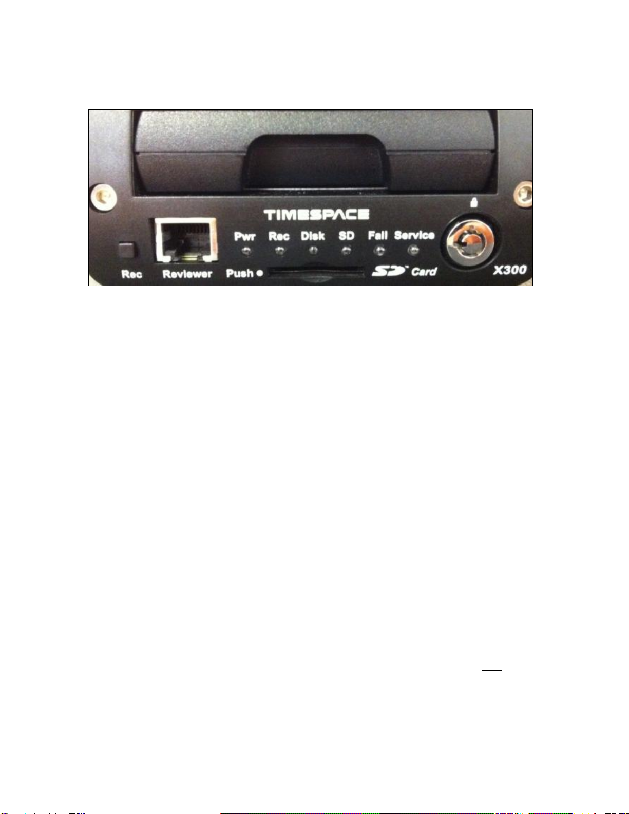
X300 Front Panel
RECORD BUTTON
Turns configured recording mode on and off. Button can be disabled within menu settings.
LED’s
Pwr - Illuminated when the X300 is powered (Green LED).
Record - Illuminated Red when the X300 is recording (flashing when in Motion Detect mode).
Disk - Pulses Green/Red when the X300 is reading/writing to/from the Cartridge or SD card.
SD - Pulses Orange when the X300 is reading/writing to/from the SD card.
Fail - Illuminated Red when any of the Fail conditions are met (refer to Service / Fail page).
Service - Illuminated Orange when any of the Service conditions are met (refer to Service / Fail
page)
At Power On - All LED‟s will illuminate whilst the X300 initialises and will remain lit during system
check (menu disabled) until the unit is operational. Once operational only the Pwr LED will remain
illuminated unless recording is taking place.
CARTRIDGE LOCK
Locked - Securely locks the removable cartridge in place and enables it for use.
Unlocked - Turns off the cartridge, releasing it for removal.
SD CARD
The X300 supports a single SD card for two configurable functions:
Dual Recording - The X300 menu settings can be configured to record up to 25 images per second to
the SD card in addition to primary images per second being recorded to the cartridge.
All additional data for example audio and gps are also included within the SD recorded
files.
File Download - Files that are recorded on the X300 Cartridge can be selected and copied to the SD
card for review on a PC.
SD Card Compatibility The X300 supports SanDisk SDHC Ultra or Extreme cards only. Sizes
include 4GB, 8GB, 16GB and 32GB. Both 15 and 30MB/s SD cards are compatible however for best
Audio playback results, 30MB/s is recommended.

12
TIMESPACE REVIEWER CONNECTOR
Connect the Timespace reviewer to X300 Reviewer socket using a standard RJ45 Ethernet cable.
Signals for this connector are as follows:
1 Video out
2 Video ground
3 Audio ground
4 RS232 Rx
5 RS232 Tx
6 Audio out (line level)
7 Power ground
8 12V
The 12V is supplied to the Reviewer from the X300. NB using greater than 12V may damage both the
X300 and the Reviewer. Never connect a laptop or PC to the front panel Reviewer socket, this will
damage the laptop/PC.

13
X300 Rear panel, common connections
RS232 CONNECTOR
9 way male D-type connector (DB9) which can be used to support 1 or 2 RS232 peripherals.
PIN TYPE I/O TYPE
3 TD, Transmit Data > Serial Data
2 RD, Receive Data < Serial Data
7 RTS, Request to send > Handshaking
8 CTS, Clear to send < Handshaking
4 DTR, Data terminal ready > X300 outputs 5V
6 DSR, Data set ready < Ignored by X300
1 DCD, Data carrier detect < Detect modem status
9 RI, Ring Indicator < Ignored by X300
5 GND, Ground
> X300 output
< X300 input
Using a conventional cable (DB9 male to DB9 female straight through (1-1, 2-2, 3-3 etc.)) the X300 can
be connected to a modem. Alternatively, two RS232 peripherals such as GSM modem and GPS device
can be connected simultaneously. Here is an example of the wiring;
PIN TYPE I/O TYPE
Device 1 (Modem)
3 TD, Transmit Data > Serial Data
2 RD, Receive Data < Serial Data
7 RTS, Request to send > Handshaking
8 CTS, Clear to send < Handshaking
1 DCD, Data carrier detect < Detect modem status
5 GND, Ground
Device 2 (GPS)
4 5V, Supply (500mA max) > Power
9 RD, Receive Data < Serial Data
5 GND, Ground
> X300 output
< X300 input
INPUT/OUTPUT CONNECTOR
10 way screw terminal block.
The X300 requires 12V regulated power. This can be applied to either via 12V DC jack socket or 12V
screw terminals. NB: Do not use both power inputs simultaneously.
Connect alarm inputs 1, 2, 3 and 4 to - terminal if closed or for open circuit leave open.
Connect alarm output to Out terminal pair.
Connect LED 1 between + and terminal LED 1, including a series resistor to limit current.

14
Connect LED 2 between + and terminal LED 2, including a series resistor to limit current.
Terminals LED 1 and LED 2 are high impedance (LAMP/LED off) or 0V (LAMP/LED on)
LED outputs 1 and 2 can be menu assigned to duplicate any of the 4 front panel LEDs (power, record,
service and fail).
ETHERNET CONNECTOR
Connect via a standard RJ45 Ethernet cable (straight i.e. pins 1-1, 2-2, 3-3 etc.) to Ethernet hub,
switch, router, wireless LAN adaptor or 3G modem.
Internal Connections: 1 Tx+, 2Tx-, 3 Rx+, 4 NC, 5 NC, 6 Rx-, 7 NC, 8 NC
The RS232 and 25 way D-type connectors use a 4-40 UNC Thread type Jack Posts. Farnell PN:
1099010:

15
X300-4 Rear Panel
Power, I/O, RS232 and LAN connections are described under Rear panel Common connections.
VIDEO CONNECTORS
1 BNC video output
4 BNC video inputs
AUDIO CONNECTOR
5 pin 180° female DIN connector (DIN 41524)
Pin
1 Audio input 1 (left)
4 Audio input 2 (right)
2 Audio GND
5 Audio output 2 (right)
3 Audio output 1 (left)
The audio signals are at line level. A 5 pin DIN to 4 way RCA phono harness can be readily purchased
from a number of suppliers. A locking connector could be used to secure the DIN in place.

16
X300-16 Rear Panel
Power, I/O, RS232 and LAN connections are described under Rear panel Common connections.
Pin numbering of both 25 Way Male D type connectors on X300 (looking at rear panel).
Video 5 - 16, Alarm In 8 Connector
Pin Pin
1 Video GND In 5 14 Video In 5
2 Video GND In 6 15 Video In 6
3 Video GND In 7 16 Video In 7
4 Video GND In 8 17 Video In 8
5 Video GND In 9 18 Video In 9
6 Video GND In 10 19 Video In 10
7 Video GND In 11 20 Video In 11
8 Video GND In 12 21 Video In 12
9 Video GND In 13 22 Video In 13
10 Video GND In 14 23 Video In 14
11 Video GND In 15 24 Video In 15
12 Video GND In 16 25 Video In 16
13 Alarm In 8

17
Video 1 - 4, Out, Switcher, Audio, Alarm In 5, 6, 7, CAN Connector
Pin Pin
1 Video GND In 1 14 Video In 1
2 Video GND In 2 15 Video In 2
3 Video GND In 3 16 Video In 3
4 Video GND In 4 17 Video In 4
5 Video GND Main Out 18 Video Main Out
6 Video GND Switcher Out 19 Video Switcher Out
7 Audio GND Out 2 (right) 20 Audio Out 2 (right)
8 Audio GND Out 1 (left) 21 Audio Out 1 (left)
9 Audio GND In 1 (left) 22 Audio In 1 (left)
10 Audio GND In 2 (right) 23 Audio In 2 (right)
11 Alarm In 5 24 Alarm In 6
12 CAN L 25 CAN H
13 Alarm In 7
X300-16 Cable Harness Recommended Specification; A common cable harness can be used for both
25 Way D type connections on the X300-16
Connector 25 Way Female D type
Shell Recommended max overall width 56mm (the two 25 way connectors are 57mm apart)
Cables 12 individual RG179 cables of suitable length.
Connections Shield pin Core Pin
Cable 1 1 14
Cable 2 2 15
Cable 3 3 16
...
Cable 12 12 25
Pin 13 not connected.
In order to meet the EMC standards with which the X300 is compliant it is important that shielded
cables are exclusively used. All of the signal grounds should be common inside the D-Type connector
and connected to a metal back-shell in order that the cable run and D-Type connector are shielded.

18
X300 DIGITAL RECORDER

19
INSTALLATION
The X300 can be used free-standing or it can be mounted using the 4 x threaded holes on the
underside - mounting screw size M4, 0.7 Pitch, 12mm).
The X300 requires 12V regulated power. This can be applied to either via 12V DC jack socket or 12V
screw terminals. NB: Do not use both power inputs simultaneously. Cameras and other external
equipment should be connected / wired to the X300 before power is applied.
Mechanical Data / fixing specification (measurements shown in mm);

20
T408 VEHICLE KIT
The following instructions are based on the Timespace X200 DVR, therefore some measurements will
vary slightly from the X300 –see INSTALLATION page of this manual for exact X300 mechanical data.
For use in mobile installations subject to shock and vibration. Please adhere to the following
instructions for the installation of the Vehicle Kit. Failure to do so may result in the Mounting System
not working correctly.
Inventory of Parts
The Vehicle Kit consists of the following parts;
QTY Description
4 Wire Rope Mounts
1 Stabiliser Coupling
8 M4 x 12mm Counter-Sunk Hex-Head Screws
In addition you will require a standard „L‟ shaped hex key. This is essential, as when all of the other
screws have been tightened, there is no room for any other tool to tighten the front lower pair of screws.
Mounting Hole Preparation
Drill four mounting holes to attach the Wire Rope Mounts. If you intend to use the M4 x 12mm screws
into blind holes, then the holes will have to be drilled and tapped to accept an M4 screw, with a thread
depth of no less than 8mm.
If mounting the Wire Rope Mounts through a metal plate, then longer screws may have to be used in
order to allow a washer and nut to be attached on the other side of the plate. The length of these
screws will have to be chosen depending on the thickness of the plate and the height of the washer and
nut.
Please note that any screw used for mounting the wire rope mounts to an enclosure surface must have
an M4 thread and have a counter-sunk hex-head.
Other manuals for X300 Series
1
Table of contents
Other Timespace DVR manuals

Timespace
Timespace X200 User manual

Timespace
Timespace K200 User manual

Timespace
Timespace X200 User manual

Timespace
Timespace X200 User manual

Timespace
Timespace K210 User manual

Timespace
Timespace OmniBase 8 User manual

Timespace
Timespace X500 User manual

Timespace
Timespace X100 User manual

Timespace
Timespace X300 Series User manual


