Timespace K200 User manual

K200
Digital Video Recorder
Instruction Manual
Designed and Manufactured in the UK
This Instruction Manual is constantly updated. To download
the latest version please go to www.tspace.co.uk
K200 Configuration Utility V1.1.2
PCLink Suite V 7.0
Kstation V1.0.0.2
©9th December 2010

K200
Digital Video Recorder
Instruction Manual
CONTENTS
SAFETY..................................................................................................................................... 3
BATTERY LIFE......................................................................................................................... 4
ENVIRONMENTAL ................................................................................................................... 5
SYSTEM OVERVIEW................................................................................................................ 6
CONNECTIONS AND CONTROLS.......................................................................................... 8
K200 Camera Wiring Recommendations............................................................................ 10
CONFIGURING THE K200 ..................................................................................................... 13
K200 Configuration Utility.................................................................................................... 14
Recording........................................................................................................................ 15
Text................................................................................................................................. 16
File System ..................................................................................................................... 17
Vibrator............................................................................................................................ 18
Advanced........................................................................................................................ 19
UPDATING THE K200 OPERATING SOFTWARE................................................................ 21
PCLINK SUITE........................................................................................................................ 22
K200 SPECIFICATION ........................................................................................................... 23
2

SAFETY
WARNING
To prevent permanent damage the battery in this unit MUST be fully recharged at least
every 3 months, even if the product is not in use.
Designed for indoor use in the temperature range 0° to 45°C, 20% to 80% RH (non-
condensing).
WARNING: Do not wet the product when cleaning.
WARNING: Do not open the K200 case - no user serviceable parts inside.
EC Declaration of Conformity (CE)
We Timespace Technology Ltd.
Blackstone Rd
Huntingdon
PE29 6TT
United Kingdom
declare that the K200 Digital Video Recorder
Meets the intent of the European Council Directive 89/336/EEC referred to as the
Electromagnetic Compatibility (EMC) Directive. The product conforms to the following
standards which have been listed in the Official Journal of the European Union.
EMC
Emissions: EN61000-6-3(2001) EMC Generic Emission Standard for residential, commercial
and light industrial. Referring to:
a) EN55022(1998) Conducted, Class B
b) EN55022(1998) Radiated, Class B
Immunity: EN61000-6-1(2001) EMC Generic Immunity Standard for residential, commercial
and light industrial. Referring to:
a) EN55024(1998) Information Technology Equipment – Immunity Characteristics
b) IEC 61000-4-6(2003) RF Field
c) EN60801-2(1993) Electrostatic Discharge
d) IEC 61000-4-4 (2004) Fast Transient
...............................................................................
Dr ROBERT HEYLEN
TECHNICAL DIRECTOR - 25th May 2006
3

BATTERY LIFE
This product uses Lithium Polymer batteries. These batteries have a high capacity, but
require regular charging to maintain this capacity.
If the unit is left uncharged for significant periods of time it is possible for the battery to self-
discharge to a level that can permanently damage the battery and significantly reduce the
capacity.
We recommend ensuring that the unit is charged at least once every three months to prevent
this, even if not in regular use.
The expected life time of this kind of battery when used correctly is 300+ re-charge cycles, or
two to three years (whichever occurs sooner) before capacity starts to reduce significantly
(below 80% of original capacity). It is normal for the capacity to reduce as the battery gets
older, and the user should expect to have the battery replaced once capacity has dropped
below an acceptable level for recording duration.
4

ENVIRONMENTAL
Temperature
The K200 is designed for indoor use in the temperature range 0° to 45°C, 20% to 80% RH
(non-condensing).
Shock and Vibration
Although the K200 is constructed from a robust extrusion every care should be taken to avoid
extremes of shock and vibration.
5

SYSTEM OVERVIEW
Warnings
To prevent permanent damage the battery in this unit MUST be fully
recharged at least every 3 months, even if the product is not in use.
The maximum rating for a camera connected to the K200 is 2W.
Connecting a higher power camera will result in permanent damage to
the K200.
Ensure camera voltage setting in Advanced Menu is the same as the
voltage of the camera actually being used; for example: if the menu
voltage is set to 12V and a 5V camera is connected, the camera can be
destroyed.
Overview
The K200 is a stand-alone digital video recorder only requiring the addition of a suitable
camera and/or microphones to record both video and audio.
The K200 is powered by an internal lithium-polymer battery and stores recordings on flash
memory. The battery and flash memory are supplied installed inside the K200.
The K200 is connected to a PC via the supplied USB2 cable. This simultaneously charges
the K200 and allows access to stored recordings and configuration of the K200.
Recording with the K200
Simply attach a suitable camera and/or microphone(s) to the K200 ‘Input’ connector which is
detailed in the Connections and Controls section of this manual.
Recording is activated either by moving the K200 toggle switch to the ‘On’ position or by using
an external trigger (as detailed in the Connections and Controls section of this manual).
When the K200 is recording the ‘Record’ LED will be lit. The amount of memory used is
displayed by the ’25, 50, 75 and 100%’ LED indicators.
Reviewing recorded footage
The K200 toggle switch must first be moved to the ‘Off – USB2’ position. The supplied USB2
cable can then be used to connect the K200 to a PC with PCLink Suite software installed.
Recorded files can then be viewed and archived using PCLink200 software. Please refer to
the PCLink200 section of this manual for further details.
6

Configuring the K200
The K200 toggle switch must first be moved to the ‘Off – USB2’ position. The supplied USB2
cable can then be used to connect the K200 to a PC.
Once connected the K200 contents window should automatically appear on the Windows
Desktop. If it does not, double click ‘My Computer’ or use Windows Explorer to locate a new
Removable Disk. Double clicking the new Removable Disk icon will open the K200 contents
window.
This window displays the contents of the K200 including any recorded .xba files and the K200
Configuration Utility.
In order to set up the K200 double click on the K200 Configuration Utility. This will then start
in a new window. The K200 Configuration Utility is covered in more detail in the Configuring
the K200 section of this manual.
7

CONNECTIONS AND CONTROLS
Input / Output Connectors
The K200 has two connectors one for USB2 and control and the other for camera and
microphone inputs.
A USB2 cable is supplied with the K200 allowing it to be connected to a USB2 port on a PC.
This is used to charge the K200 battery and also to allow configuration of the K200 and
access to any stored recording files.
The input connector is supplied with the K200, but appropriate cable connections will have to
be made in order to attach cameras and/or microphones.
The pin assignments for each of the connectors are shown in the following diagram.
Record/USB2 Switch
The K200 toggle switch controls whether the K200 is recording (switch in the ‘On’ position) or
whether it is connected to the PC (switch in the ‘Off’ position).
8

LED Indicators
The K200 has a number of LED’s to indicate certain conditions.
Record – Indicates that the K200 is currently recording.
Charging – Indicates that the K200 battery is currently being charged. When this LED goes
out whilst still connected to the PC the K200 is fully charged.
Low Bat – Indicates that the K200 battery is low and will need charging soon to avoid a
cessation of recording.
Memory Used – Gives an indication as to how much of the K200 memory is full of recording,
LED’s will light at 25, 50, 75 and 100% full.
The K200 LED’s can be software disabled by selecting ‘LEDs Disabled’ in the Advanced
Menu of the K200 Configuration Utility. If this is selected then none of the K200 LED’s will
light at any time which may be of use in covert applications.
Vibrator Output Diagram
9

K200 Camera Wiring Recommendations
Introduction
The K200 is supplied with a Fischer plug + 4.7mm collet, for connecting your choice of
camera to the K200 unit. This plug mates with the Input connector of the K200 and is the only
plug suitable for use. This document provides some hints for preparing this connector.
***Caution***
A high level of wiring and soldering skill is required to successfully connect to the plug
supplied. The contacts are very small and therefore there it is easy to short
connections together, possibly damaging your K200. Please ensure you have sufficient
skills before attempting this task.
Parts Supplied
The Fischer connector is supplied in 2 parts: The plug and the collet set. You need both parts
to complete the task successfully. If you fail to fit the collet set, the pins will withdraw when the
connector is inserted.
Fig 1. Connector parts.
Fig 2. Complete connector
10

Assembly Sequence
1. Determine the diameter of the cable you are using. The maximum size for the
connector is 4.7mm overall diameter. The maximum wire size to fit the solder buckets
is 28AWG.
2. If the cable you are using is less than 4.3mm, you will need to either source an
alternative collet, or build up the diameter of the cable by using heatshrink tubing. It is
recommended that the adhesive-lined type is used if using heatshrink tubing as it
provides greater cable strain relief. You should use a minimum of 30mm of heatshrink
tubing.
3. Working from the end to be connected, slide the cable clamp onto the cable.
4. Slide the Collet onto the cable.
5. Strip the insulation from your cable exposing any screening present. You should strip
back approximately 40mm but this will be trimmed back later.
6. Splay out any screening. Once the screening has been splayed out, slide the spacer
over the wire cores.
7. Trim the cores to 15mm.
8. Strip the ends approximately 1mm and tin the exposed wires with a minimum amount
of solder. If you use too much, you will struggle to fit the wires into the solder buckets
of the insert.
9. Slide the spacer over the cores.
10. Solder the cores into the solder buckets of the insert. *This is Tricky!*. Start from pin 1
(the centre connector) and use a minimal amount of solder in order to minimise the
risk of short circuits. A ‘helping hands’ tool is very useful here.
11. Wire the connector up as per the diagram below.
Fig 4. Connections
11

12. Once all the connections have been made, trim back any unused cores as close to
the stripped end as possible.
13. Slide the space up towards the insert. If you rotate the space around the cable, you
will find that it ‘keys’ into the insert in one position only.
14. Slide the collet into the space, trapping the splayed out screen (if present) between
the collet and the spacer. Trim the screen that protrudes from this gap.
15. Slide the plug body over the insert and onto the cable
***NOTE***
The insert will only go into the plug in one way. It is keyed to align with the keying
in the body. Some pressure is needed once these align, but no more than gentle
pressure is needed once it has aligned.
16. When the insert is nearly fully home, rotate the collet around the cable so the small
bump on the collet aligns with the slot in the body. Once these align, the insert and
cable can be pushed fully home.
17. Push the collet up into the body as far as you can.
18. Tighten the cable clamp onto the body.
Your connector is now complete and ready for use.
Fischer Information
Fischer part no Description
S102A056-130+ K200 input plug
S102A056-230+ K200 control plug
E32 102.1/2.1+A 2.1mm collet (1.5 – 2.1 cable)
E32 102.1/2.6+A 2.6mm collet (2.1 – 2.6 cable)
E32 102.1/3.1+A 3.1mm collet (2.6 – 3.1 cable)
E32 102.1/3.6+A 3.6mm collet (3.1 – 3.6 cable)
E32 102.1/4.1+A 4.1mm collet (3.6 – 4.1 cable)
E32 102.1/4.3+A 4.3mm collet (4.1 – 4.3 cable)
102.248 + A 4.7mm collet (4.3 – 4.7 cable)
Distributor list available on: www.fischerconnectors.com
12

CONFIGURING THE K200
The K200 is configured by connecting it to a PC via the supplied USB2 cable.
The ‘Record’ toggle switch must be in the ‘Off – USB2’ position.
The K200 contents window should then automatically appear on the Windows Desktop. If it
does not, double click ‘My Computer’ or use Windows Explorer to locate a new Removable
Disk. Double clicking the new Removable Disk icon will open the K200 contents window
which is shown below.
This window displays the contents of the K200 including any recorded .xba files and the K200
Configuration Utility.
In order to set up the K200 double click on the K200 Configuration Utility. This will then start
in a new window.
13
K200 Configuration Utility
The K200 Configuration Utility allows the user to change any of the K200 settings and then
save them in its internal flash memory. Please note that none of the changes will be saved
until the ‘Save Settings’ button is pressed.
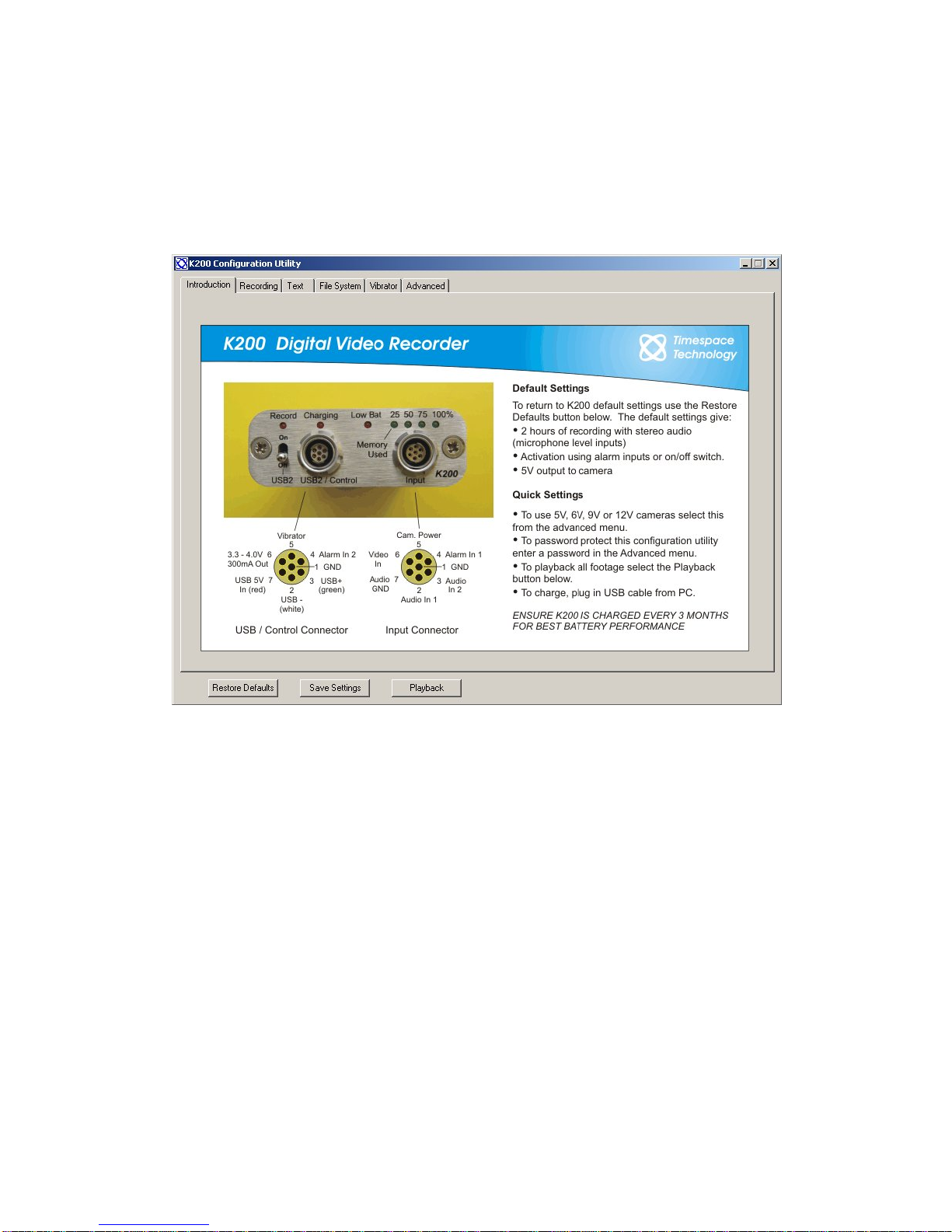
When the K200 Configuration Utility starts the user will see the following window.
This is an introductory screen showing the K200 connectors and controls and the main default
settings.
The configuration Utility is organised into a series of 5 menu pages (in addition to the
Introduction page) which can be accessed via the tabs at the top of the utility window.
The three buttons at the bottom left of the window allow the user to restore the default K200
settings, save the new settings to the K200 internal memory or playback any .xba files
currently stored on the K200 by launching PCLink200 reviewing and archiving software.
These three buttons appear in the same location on every page of the utility.
The pages themselves are laid out so that the settings are on the left hand side of the utility
and a section of help text is on the right hand side.
14

Recording
Recording can be started by moving the K200 toggle switch to the ‘ON’ position. Moving the
switch to the ‘Off – USB2’ position will stop recording. Recording can also be controlled by
external switches which are used to connect pins 4 and 1 on the ‘Input’ connector (Alarm In 1)
or pins 4 and 1 on the ‘USB2/Control’ connector (Alarm In 2).
A timer is also included to start recording at a specified time (the K200 battery capacity will be
used during hibernation until recording commences which will result, in less recording time
than the maximum of 2 hours). As an example if the K200 has to wait the maximum time until
recording of 24 hours only 50 – 60 minutes of recording will be made if the battery was initially
fully charged.
If ‘Timer at’ has been selected as the trigger to start recording the K200 toggle switch should
still be set to the On – Record’ position once disconnected from the PC. If it is left in the ‘Off -
USB2’ position the timer will not activate recording.
Recording started by – Defines which controls will start/stop recording. If ‘Timer at’ is
selected then the switch and alarm inputs will be disabled.
Record – Selects whether the K200 will record constantly (video) or capture from 1 to 500
images and then stop recording.
When the switch or alarm is switched off – Determines whether the K200 immediately
stops recording or continues to record from 5 seconds up to 5 minutes.
Mode – Selects whether audio recording is in mono, stereo or turned off.
Record Input Range – Selects the input range of the K200 audio inputs. An appropriate
range should be chosen depending on the specification of the microphones being used. The
K200 has a built in pre-amp, if a pre-amp is being used on the inputs then this setting will
need adjusting down.
Last recording peak input – Shows the peak input voltage from the microphones during the
last recording. This can be used as a guide when setting a value for the record input range.
The K200 battery allows a maximum of 2 hours of recording before it requires recharging.
15

Text
The user definable text fields allow text to be embedded in the recorded images when the
Alarm Inputs are either open or closed.
The K200 internal clock can also be set to a specific date and time. This will take effect once
the settings have been saved to the K200 and it is next powered up (the toggle switch is
moved to the ‘On’ position).
Embed Time, Date and Camera Text – When this box is checked the time and date will be
embedded in all recorded images along with any user defined Alarm Input text.
Camera Text When Alarm Input is Open (default) – The user can enter text in this field to
be embedded into the recorded images whilst the Alarm Inputs are open.
Camera Text When Alarm Input is Closed – The user can enter text in this field to be
embedded into the recorded images whilst the Alarm Inputs are closed.
Position – Determines the position of text within the recorded images.
Summer Time Adjust – Determines whether the K200 internal clock will automatically adjust
for UK/USA/EUROPE summertime or not if set to ‘OFF’.
Mode – Determines whether the date is in the format DD/MM/YYYY or MM/DD/YYYY.
Set Date/Time at Next Power On – Allows the user to adjust the K200 internal clock. The
new settings will only become active once the ‘Save Settings’ button has been pressed (all
new settings saved to the K200) and the K200 has been powered up by moving the toggle
switch to the ‘On’ position.
Time – The time in 24 hour format.
Date – The date in the format DD/MM/YYYY or MM/DD/YYYY determined by the ‘Mode’
setting.
All embedded text is protected by the fragile watermarking system used in the K200 and
PCLink200. This gives a positive indication as to whether recorded images are original or
whether they may have been tampered with after recording.
16

File System
The File System settings determine how the K200 stores recordings and whether it stops
recording when the memory is full, or loops around and starts to overwrite oldest recordings
first.
Recording Mode – This K200 can be set to either stop recording when the memory is full
(Single Pass) or start to overwrite oldest (non write-protected) recordings first (Loop Record).
Maximum File Duration – If set to unlimited the K200 will create a new file each time
recoding starts. If it is desirable to further break down recorded footage into smaller pieces
the 10 minute option can be chosen limiting the maximum individual file duration to this
period.
Filename Prefix Text – The user definable text in this field will prefix the file name of any
recording files which by default are named by the time and date of creation.
17

Vibrator
The K200 has an output (pin 5 on the USB2 / Control Connector) which can be connected to
a suitable actuator such as a buzzer/vibrator. This is intended to give a discreet covert
indication of various user defined conditions.
Power On Feedback – The vibrator output will produce 1-5 short or long pulses when the
K200 is turned on and recording commences.
Power Off Feedback – The vibrator output will produce 1-5 short or long pulses when the
K200 is turned off and recording ceases.
Capacity Feedback – The vibrator output will produce 1-5 short or long pulses when the
K200 memory is a user defined percentage used from 1-100%. There are 5 independent
settings allowing the user to set various patterns of pulses for different percentages used.
18

Advanced
This section of the K200 Configuration Utility allows the user to set a number of preferences.
Video Standard – Selects whether the K200 is to be used with PAL or NTSC cameras.
Camera Voltage – Selects the appropriate camera voltage supplied by the K200.
Please be careful not to exceed the connected camera’s voltage rating as this can
cause permanent damage to the camera.
LEDs – Disables or enables the K200 LED indicators.
Set Application Password – A password can be entered in order to prevent unauthorized
access to the K200 Configuration Utility.
Set Camera Voltage Password – A password can be entered in order to prevent
unauthorized changes to the supplied camera voltage.
System Information – Displays information about the K200.
In addition there are two buttons at the bottom of the Advanced Menu. Format Disk will
completely clear all recordings and menu settings from the K200 the next time it is turned on
(by moving the toggle switch to the ‘On – Recording’ position). This should only ever be used
to completely reset the K200 system.
The Delete Recordings button will remove all recording files from memory but leave the menu
settings unchanged.
19

*Note – the battery remaining reading is only updated when the K200 is plugged in and the
configuration utility started. It does not dynamically changed whilst charging. Disconnect and
reconnect the K200 to refresh the reading.
20
Table of contents
Other Timespace DVR manuals

Timespace
Timespace X300 Series User manual

Timespace
Timespace X200 User manual

Timespace
Timespace X300 Series User manual

Timespace
Timespace X500 User manual

Timespace
Timespace X200 User manual

Timespace
Timespace X200 User manual

Timespace
Timespace X100 User manual

Timespace
Timespace K210 User manual

Timespace
Timespace OmniBase 8 User manual


