manuals.online logo
Brands
  1. Home
  2. •
  3. Brands
  4. •
  5. CDI Meters
  6. •
  7. Measuring Instrument
  8. •
  9. CDI Meters CDI 25 Series User manual

CDI Meters CDI 25 Series User manual

©2019 CDI Meters, Inc. 10.19
CDI 25 Flowmeter
Installation and Operating Instructions
Limitations and Cautions
CDI 25 flowmeters are not for use in hazardous areas or on pipes containing
gasses other than air or nitrogen, at pressures from atmospheric to 200 psig.
They are not designed for installation under pressure and they are not for use in
control safety applications. The temperature compensation of the meters is
suitable for use from 20 to 120°F (-7 to 49°C).
Location
For accurate and reliable readings, the meters must be installed with adequate
straight upstream pipe, and, in compressed-air applications, they must be
installed downstream of a dryer.
Select a location with a straight run of pipe upstream equal to at least twenty
times the diameter. If the meter is downstream of something that could distort or
concentrate the flow, such as a sweep elbow, a partially-closed valve, an
increase in pipe size or a hose, the run of pipe should be as long as possible;
thirty times the diameter at a minimum. Five diameters of straight downstream
pipe is sufficient, unless the meter is immediately upstream of something that
would restrict the flow, such as a valve. Select a location that meets these
requirements and also provides good visibility.
Preparing the Holes
When the holes are drilled, metal shavings will enter the pipe. Make sure that
filters or other provisions are present downstream to prevent the shavings from
damaging equipment or product or being blown out and causing injury.
Shut down the air and make sure that it will remain shut off while the meter is
being installed. Before starting to drill the holes, make sure that the air pressure
is completely bled down. Use the CDI 5200-DG drill guide. Secure the drill guide
to the pipe with a C clamp, a hose clamp or a chain clamp. If using a C clamp,
make sure that it is centered across the pipe. Drill the holes, remove the drill
guide, and remove any burrs that were formed when you drilled the holes. If the
pipe is rough near the holes, smooth it with a file.
Apply the “Holes in Pipe” decal so that it will be hidden when the meter is in place
but will be revealed when it is removed.
©2019 CDI Meters, Inc. 10.19
Installing the Meter
Make sure the probes are clean. If there is any oil or dirt on them, clean them
with alcohol or a similar degreaser. Insert the band clamps into the slots provided
for them and then insert the probes into the holes in the pipe, with the flow arrow
pointing in the proper direction. Engage and tighten the band clamps.
Wiring the Meter
The meter requires 24 Volt dc power. Insert the power-supply cable through the
grommet at the bottom of the meter. Connect the positive lead to the dc+
terminal, the negative lead to the dc- terminal and the shield, if one is present, to
the gnd terminal. If you are using the wall-plug supply and adaptor cable
provided by CDI, the band-marked lead (not the printed lead) is positive.
Programming the Monitoring Functions
The meter has four display modes: rate, minimum, average and total. The display
is controlled by a button on the underside of the meter. Pressing the button
repeatedly will cycle the display through the four modes; LEDs above the digital
display indicate which mode is active; when no LED is lit, the meter is in the rate
mode.
Minimum and Average Modes
The minimum and average functions look back over periods of time specified by
the user. Each is based on 360 samples taken over the specified period of time.
Minima and averages are calculated and stored for groups of 36 samples, so the
displayed results are updated at an interval of one tenth of the period specified
by the user. Thus, if the average is computed over 0.1 hour (six minutes), the
flow will be sampled every second and the display will update every 36 seconds.
Please note that, since the minimum and average are based on data stored in
memory, they will not be meaningful until the specified period has elapsed.
Total Mode
Cumulative air usage is displayed in thousands of cubic feet, or in cubic meters.
The total is not resettable.
Filter
A simple digital filter is provided for situations in which flow is continuously
varying and a steady, filtered display is useful. If the filter factor is programmed to
zero (see below) there is no filtering. If it is one, the current value is averaged in
equal parts with the previous filtered value. If it is two, one quarter of the present
value is added to three quarters of the previous filtered value, and so on, with
factors available up to six. Filtered values are used in calculating minima and
©2019 CDI Meters, Inc. 10.19
averages. Please note that the meter has limited sensitivity to very short pulses
of air flow, and filtering or averaging the output does not alter this.
Alarms
If user-specified thresholds for minimum or average are exceeded, indicating
excessive air usage, the corresponding LEDs will blink. These blinks are short,
with the LED lit one eighth of the time. If the same LED is lit to indicate the
current display mode, it will blink off for one eighth of the time.
Units of Measure
Five options of units are available. Units should be set in accordance with local
custom and should match the markings on the cover of the meter.
Programming
With the meter displaying rate, press and hold the button. The minimum LED will
light immediately; when the average LED lights, release the button. The display
will now show two letters on the left and two digits, with or without a decimal
point, on the right. The letters indicate which parameter is being programmed;
the digits indicate the current value of the parameter. When a three-digit
parameter is displayed, one of the letters will be overwritten. To advance the
parameter, press and release the button; to advance the parameter rapidly, press
and hold the button. To advance to the next parameter, just wait. Time is
displayed in hours and tenths of hours.
symbol
meaning
description
range
LL
Low Limit
Threshold for minimum
flow alarm
0.1 cfm to
99 cfm
LP
Low Period
Period over which
minimum flow is
calculated (hours)
0.1 hr to
24 hr
AL
Average Limit
Threshold for average
flow alarm
0.1 cfm to
99 cfm
AP
Average
Period
Period over which
average flow is
calculated (hours)
0.1 hr to
24 hr
FF
Filter Factor
Degree of filtering
0 –no filtering
6 –maximum filtering
dd
default
display
0 –rate
1 –minimum
2 –average
3 –total
du
display units
Rate
0 –cfm
1 –Nm3/hr at 0 deg C
2 –Nm3/hr at 20 deg C
3 –Nm3/min at 0 deg C
4 –Nm3/min at 20 deg C
Total
1000 cuft
m3 at 0 deg C
m3 at 20 deg C
m3 at 0 deg C
m3 at 20 deg C
cdimeters
CDI Meters, Inc.
3R Green Street, Woburn, MA 01801
email: [email protected]
call toll free: 866-885-2462
www.cdimeters.com
Maintenance
If oil or dirt accumulates on the probes, the meter will read inaccurately. For this
reason, we recommend cleaning the probes from time to time. To clean the
probes, wipe them with a cloth dampened with alcohol or a similar degreaser. It
may be found that the system is clean enough that cleaning is not needed.
Warranty
CDI warrants solely to the buyer that the Model 25 Flowmeter shall be free from
defects in materials and workmanship, when given normal, proper and intended
usage, for three years from the date of purchase. During the warranty period, CDI will
repair or replace (at its option) any defective product at no cost to the buyer. The
foregoing warranty is in lieu of any other warranty, express or implied, written or oral
(including any warranty of merchantability or fitness for a particular purpose). CDI’s
liability arising out of the manufacture, sale or supplying of the flowmeter, whether
based on warranty, contract, tort or otherwise, shall not exceed the actual purchase
price paid by the buyer, and in no event shall CDI be liable to anyone for special,
incidental or consequential damages.

This manual suits for next models

5

Other CDI Meters Measuring Instrument manuals

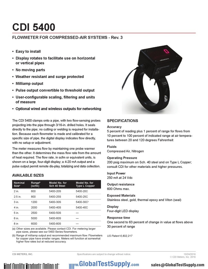
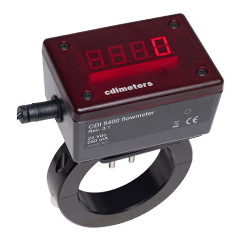
CDI Meters CDI 5400 User manual

CDI Meters

CDI Meters CDI 5400 User manual

CDI Meters CDI 5400 User manual

CDI Meters

CDI Meters CDI 5400 User manual

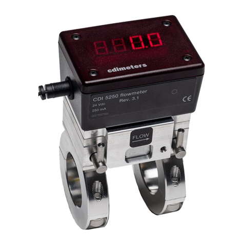
CDI Meters 5250 User manual

CDI Meters

CDI Meters 5250 User manual

CDI Meters CDI 5450 User manual

CDI Meters

CDI Meters CDI 5450 User manual

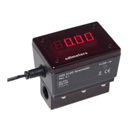
CDI Meters CDI 5100 User manual

CDI Meters

CDI Meters CDI 5100 User manual

CDI Meters CDI 25 User manual

CDI Meters

CDI Meters CDI 25 User manual

CDI Meters 5400 User manual

CDI Meters

CDI Meters 5400 User manual

CDI Meters CDI 25 User manual

CDI Meters

CDI Meters CDI 25 User manual

Popular Measuring Instrument manuals by other brands

hecht 2003 TRANSLATION OF ORIGINAL INSTRUCTIONS FOR USE

hecht

hecht 2003 TRANSLATION OF ORIGINAL INSTRUCTIONS FOR USE

Hitachi SML44 instruction manual

Hitachi

Hitachi SML44 instruction manual

SMC Networks PPA100 Series instruction manual

SMC Networks

SMC Networks PPA100 Series instruction manual

Waltron 9096 user manual

Waltron

Waltron 9096 user manual

LaserLiner AutoCross-Laser 360 PowerBright operating instructions

LaserLiner

LaserLiner AutoCross-Laser 360 PowerBright operating instructions

eHealthcare H100 user manual

eHealthcare

eHealthcare H100 user manual

PCB Piezotronics J356B08 Installation and operating manual

PCB Piezotronics

PCB Piezotronics J356B08 Installation and operating manual

Doyon WM35 manual

Doyon

Doyon WM35 manual

Eurotops M320 manual

Eurotops

Eurotops M320 manual

Knauer K-7400S user manual

Knauer

Knauer K-7400S user manual

Chauvin Arnoux Ulys MD45 Series quick start

Chauvin Arnoux

Chauvin Arnoux Ulys MD45 Series quick start

CNC CNCWL- 5136-XN Operator's manual

CNC

CNC CNCWL- 5136-XN Operator's manual

GLI International P33 Operating instructions manual

GLI International

GLI International P33 Operating instructions manual

Teledyne Lecroy WaveMaster 8000HD Getting started guide

Teledyne Lecroy

Teledyne Lecroy WaveMaster 8000HD Getting started guide

DAKOTA ULTRASONICS UMX-2 Operation manual

DAKOTA ULTRASONICS

DAKOTA ULTRASONICS UMX-2 Operation manual

Thermo Scientific AutoXP manual

Thermo Scientific

Thermo Scientific AutoXP manual

Spirax Sarco MTI10 Insertion Installation and maintenance instructions

Spirax Sarco

Spirax Sarco MTI10 Insertion Installation and maintenance instructions

Sartorius LMA200PM operating instructions

Sartorius

Sartorius LMA200PM operating instructions

manuals.online logo
manuals.online logoBrands
  • About & Mission
  • Contact us
  • Privacy Policy
  • Terms and Conditions

Copyright 2025 Manuals.Online. All Rights Reserved.