Toa TS-D1000 Series User manual

INSTRUCTION MANUAL
Thank you for purchasing TOA’s Digital Conference System.
Please carefully follow the instructions in this manual to ensure long, trouble-free use of your equipment.
DIGITAL CONFERENCE SYSTEM
TS-D1000 SERIES
Master control unit
Chairman unit
Delegate unit

2
TABLE OF CONTENTS
1. SAFETY PRECAUTIONS ............................................................................. 4
2. GENERAL DESCRIPTION .......................................................................... 6
3. FEATURES ............................................................................................................ 6
4. AVAILABLE INSTRUCTION MANUALS ............................................ 6
5. NOMENCLATURE AND FUNCTIONS ................................................. 7
5.1. TS-D1000-MU Master Control Unit ...................................................................... 7
5.2. TS-D1000-SU Sub Control Unit ........................................................................ 10
5.3. TS-D1000-EX Extension Unit ............................................................................ 11
5.4. TS-D1000-CU Chairman Unit ........................................................................... 12
5.5. TS-D1000-DU Delegate Unit ............................................................................. 14
6. CONFERENCE SYSTEM OPERATION ............................................. 16
6.1. Requesting Permission to Speak ....................................................................... 16
6.2. Initiating Priority Speech (TS-D1000-CU Chairman Unit Only) ......................... 17
7. USING THE RECORDING FUNCTION .............................................. 19
7.1. Notes on Use ...................................................................................................... 19
7.2. Usable USB Memory Devices ........................................................................... 19
7.3. Sound Source File Specifications and Filenames .............................................. 20
7.4. Recording to a USB Memory Device .................................................................. 21
7.5. Recording to the Internal Memory ...................................................................... 22
8. SYSTEM EXAMPLES ................................................................................... 23
8.1. Basic System Example ....................................................................................... 23
8.2. Expanded System Example – Connected Unit Expansion ............................... 24
8.3. Expanded System Example – Distance Extension ............................................ 25
9. CONNECTIONS ............................................................................................... 26
9.1. Power Supply Connections ................................................................................. 26
9.2. Signal Ground Connections ............................................................................... 26
9.3. Conference Unit and Sub Control Unit Connections ......................................... 27
9.4. LAN Connection ................................................................................................. 27
9.5. External Device Connections ............................................................................. 27
10. INSTALLATION .............................................................................................. 28
10.1. Mounting the Control Unit in an Equipment Rack ............................................. 28
10.2. Microphone Connection ................................................................................... 30
10.3. Connection Test ............................................................................................... 30
11. SETTINGS ......................................................................................................... 31
11.1. Conference Mode Setting ................................................................................. 31
11.2. Max. Open Mic No. Setting .............................................................................. 32
11.3. Mic Auto-Off Setting ......................................................................................... 33
11.4. Conference Unit Monitor Volume Setting ......................................................... 34
11.5. Setting Lock ...................................................................................................... 35

3
12. BROWSER SETTING ................................................................................ 36
13. FEEDBACK SUPPRESSION MEASURES ................................... 37
13.1. Internal FBS Function ....................................................................................... 37
13.2. Using an External Processor ........................................................................... 37
14. IF A FAILURE IS DETECTED ............................................................... 38
14.1. TS-D1000-MU Master Control Unit ................................................................... 38
14.2. TS-D1000-SU Sub Control Unit ....................................................................... 39
14.3. TS-D1000-EX Extension Unit .......................................................................... 39
14.4. TS-D1000-CU Chairman Unit and TS-D1000-DU Delegate Unit .................... 39
15. SPECIFICATIONS ........................................................................................ 41
15.1. TS-D1000-MU Master Control Unit .................................................................. 41
15.2. TS-D1000-SU Sub Control Unit ...................................................................... 42
15.3. TS-D1000-EX Extension Unit ........................................................................ 43
15.4. TS-D1000-CU Chairman Unit .......................................................................... 43
15.5. TS-D1000-DU Delegate Unit ........................................................................... 44
15.6. TS-D1000-M1 Standard Microphone and TS-D1000-M2 Long Microphone ... 44

4
1. SAFETY PRECAUTIONS
• Before installation or use, be sure to carefully read all the instructions in this section for correct and safe
operation.
• Be sure to follow all the precautionary instructions in this section, which contain important warnings and/or
cautions regarding safety.
• After reading, keep this manual handy for future reference.
Applicable to TS-D1000-MU, TS-D1000-CU, TS-D1000-DU, TS-D1000-SU, and TS-D1000-EX
• Do not expose the unit to rain or an environment where it may be splashed by water or other liquids, as doing
so may result in re or electric shock.
• Avoid installing or mounting the unit in unstable locations, such as on a rickety table or a slanted surface.
Doing so may result in the unit falling down and causing personal injury and/or property damage.
• Since the unit is designed for indoor use, do not install it outdoors. If installed outdoors, the aging of parts
causes the unit to fall off, resulting in personal injury. Also, when it gets wet with rain, there is a danger of
electric shock.
• Should the following irregularity be found during use, immediately switch off the power, disconnect the power
supply plug from the AC outlet and contact your nearest TOA dealer. Make no further attempt to operate the
unit in this condition as this may cause re or electric shock.
· If you detect smoke or a strange smell coming from the unit
· If water or any metallic object gets into the unit
· If the unit falls, or the unit case breaks
· If the power supply cord is damaged (exposure of the core, disconnection, etc.)
· If it is malfunctioning (no tone sounds)
• To prevent a re or electric shock, never open nor remove the unit case as there are high voltage components
inside the unit. Refer all servicing to qualied service personnel.
• Do not place cups, bowls, or other containers of liquid or metallic objects on top of the unit. If they accidentally
spill into the unit, this may cause a re or electric shock.
Applicable to TS-D1000-MU, TS-D1000-SU, and TS-D1000-EX
• Use the unit only with the voltage specied on the unit. Using a voltage higher than that which is specied
may result in re or electric shock.
• Do not cut, kink, otherwise damage nor modify the power supply cord. In addition, avoid using the power cord
in close proximity to heaters, and never place heavy objects -- including the unit itself -- on the power cord,
as doing so may result in re or electric shock.
• Do not touch a power supply plug during thunder and lightning, as this may result in electric shock.
Applicable to TS-D1000-MU, TS-D1000-CU, and TS-D1000-DU
• Do not insert nor drop metallic objects or ammable materials in the ventilation slots of the unit’s cover as this
may result in re or electric shock.
Indicates a potentially hazardous situation which, if mishandled, could
result in death or serious personal injury.
WARNING

5
Applicable to TS-D1000-MU, TS-D1000-CU, and TS-D1000-DU
• To prevent possible hearing damage, do not listen at high volume levels for long periods.
Indicates a potentially hazardous situation which, if mishandled, could
result in moderate or minor personal injury, and/or property damage.
CAUTION
Applicable to TS-D1000-MU, TS-D1000-CU, TS-D1000-DU, TS-D1000-SU, and TS-D1000-EX
• Avoid installing the unit in humid or dusty locations, in locations exposed to the direct sunlight, near the
heaters, or in locations generating sooty smoke or steam as doing otherwise may result in re or electric
shock.
• Do not place heavy objects on the unit as this may cause it to fall or break which may result in personal injury
and/or property damage. In addition, the object itself may fall off and cause injury and/or damage.
Applicable to TS-D1000-MU, TS-D1000-SU, and TS-D1000-EX
• Never plug in nor remove the power supply plug with wet hands, as doing so may cause electric shock.
• When unplugging the power supply cord, be sure to grasp the power supply plug; never pull on the cord itself.
Operating the unit with a damaged power supply cord may cause a re or electric shock.
• When moving the unit, be sure to remove its power supply cord from the wall outlet. Moving the unit with the
power cord connected to the outlet may cause damage to the power cord, resulting in re or electric shock.
When removing the power cord, be sure to hold its plug to pull.
• Use the specied AC adapter for the unit. Note that the use of other adapter may cause a re.
• If dust accumulates on the power supply plug or in the wall AC outlet, a re may result. Clean it periodically.
In addition, insert the plug in the wall outlet securely.
• Switch off the power, and unplug the power supply plug from the AC outlet for safety purposes when cleaning
or leaving the unit unused for 10 days or more. Doing otherwise may cause a re or electric shock.
Applicable to TS-D1000-MU and TS-D1000-SU
• Be sure to follow the instructions below when rack-mounting the unit. Failure to do so may cause a re or
personal injury.
· Install the equipment rack on a stable, hard oor. Fix it with anchor bolts or take other arrangements to
prevent it from falling down.
· When connecting the unit’s power cord to an AC outlet, use the AC outlet with current capacity allowable to
the unit.
· The rack-mounting screws supplied with the optional rack-mounting brackets* can be used for the TOA
equipment rack only. Do not use them for other rack.
* For TS-D1000-MU : MB-TS920
For TS-D1000-SU : MB-15B-BK, MB-15B-J
Applicable to TS-D1000-MU, TS-D1000-SU, TS-D1000-EX, TS-D1000-CU, and TS-D1000-DU
Warning: Operation of this equipment in a residential environment could cause radio interference.

6
2. GENERAL DESCRIPTION
The TOA TS-D1000 Series is a conference system specially designed for easy set up, disassembly and storage.
It can be used by merely connecting a number of conference units* to the TS-D1000-MU Master control unit.
Up to 32 Conference units can be connected. This number can be increased to up to 246 units (up to
2 Chairman Units) by further connecting a maximum of 5 TS-D1000-SU Sub control units.
* Collective name of the two models: TS-D1000-CU Chairman unit and TS-D1000-DU Delegate unit
3. FEATURES
• By simply connecting the required number of Conference units to the Master control unit, the system’s fully
digital audio processing system can clearly amplify all conference participant voices.
• Up to 32 Conference units can be connected to each Master control unit (1 line: 16 units × 2 lines).
• Up to 246 Conference units can be connected in a system if the maximum of 5 Sub control units are also
used.
• Inter-equipment connections can be performed in a daisy chain conguration using Cat5e STP LAN cable.
• Either ’Standard’ or ’Long’ versions of the exible microphone arm can be selected for use with the Conference
unit.
• The Conference unit’s microphone arm is designed to be easily detachable for space-saving storage.
• A test function allows easy conrmation of the Conference unit’s connection status.
• Conference mode can be selected for more effective operation during conference proceedings.
• The number of Delegate units that can simultaneously speak can be limited using the Max. open mic No.
restriction function.
• The Mic auto-off function automatically turns off the microphone after approximately 30 seconds, even if the
user forgets to turn off the microphone after speaking.
• Since the Master control unit is provided with its own individual recording function, the contents of the
conference can be recorded to either internal memory or a commercially-available USB memory device.
External recording devices can also be connected.
• The Master control unit’s power save function automatically powers down the system if the user forgets to turn
the power off.
• Conference units can be set to mute the monitor speaker or reduce sound volume when the microphone is
switched ON to eliminate concerns about feedback (howling).* Even if feedback briey occurs, the Master
Control unit’s feedback suppressor (FBS) function provides highly effective control.
* Squeal or howling sounds caused by a feedback loop created when the microphone picks up sound output
from the speaker, which is then further amplied by an amplier.
4. AVAILABLE INSTRUCTION MANUALS
The following two instruction manuals are made available for the TS-D1000 Series digital conference system:
Manual Name Manual Outline Remarks
(1) Instruction manual General explanations of installation,connection,
operation, settings, etc
The manual currently in hand
(2) Instruction manual
(Browser settings)
Explanation of browser settings Web only
Note
Regarding (2) above, since some items can only be set using a web browser, download the manual from the
TOA DATA Library. (https://www.toa-products.com/international/).

7
5. NOMENCLATURE AND FUNCTIONS
5.1. TS-D1000-MU Master Control Unit
[Top]
3 4 5 6 7 8
13
1
14
15
21
22
23
2
24 25 2619 20
17
10
9
11 12
18
16
1. Power switch (For 24 V DC)
Press this switch to turn the Power ON. Press the
switch again to switch the power OFF.
Note
The TS-D1000-MU is equipped with a Power save
function. If any device connected to the system,
including Conference units, is not operated for
more than two hours, power is automatically
turned OFF. However, when recording or speech
operations are in progress, the power turns off two
hours after such operations are terminated.
2. Power indicator (White)
Lights when power is turned ON.
3. Conference mode selector key
Used to select one of the following four conference
modes when a Conference unit’s Talk key is
pressed and the allowable number of speaking
Delegate units is exceeded:
• Standard (factory default setting)
• Override
• Voice activation
• Chairman only
Note
Refer to "Conference Mode Setting" on p. 31 for
details regarding each conference mode.
4. Conference mode indicators (Green)
The indicator corresponding to the selected by
conference mode selector key (3) lights.
5. Max. open mic No. setting Key
Used to set the number of units that can be used
simultaneously. Max. open mic No. indicators 1, 2
and 8 show the number of Delegate unit who can
simultaneously speak. (See "Max. Open Mic No.
Setting" on p. 32.)
6. Max. open mic No. indicators (Green)
The indicator that corresponds to the number of
speaking parties (selected with the Max. open mic
No. setting key) (5) lights.
All indicators light when the Max. open mic No. is
set to between 3 and 7 using the browser.
All indicators remain unlit when Voice activation
or Chairman only modes are selected using the
Conference mode selector key (3).
7. Mic auto-off setting key
Delegate unit microphones can be set to
automatically disable approximately 30 seconds
after speaking ends if the user forgets to turn it
OFF. The function switches between Enabled and
Disabled with each depression of this key.
Note
Factory preset to Disabled.

8
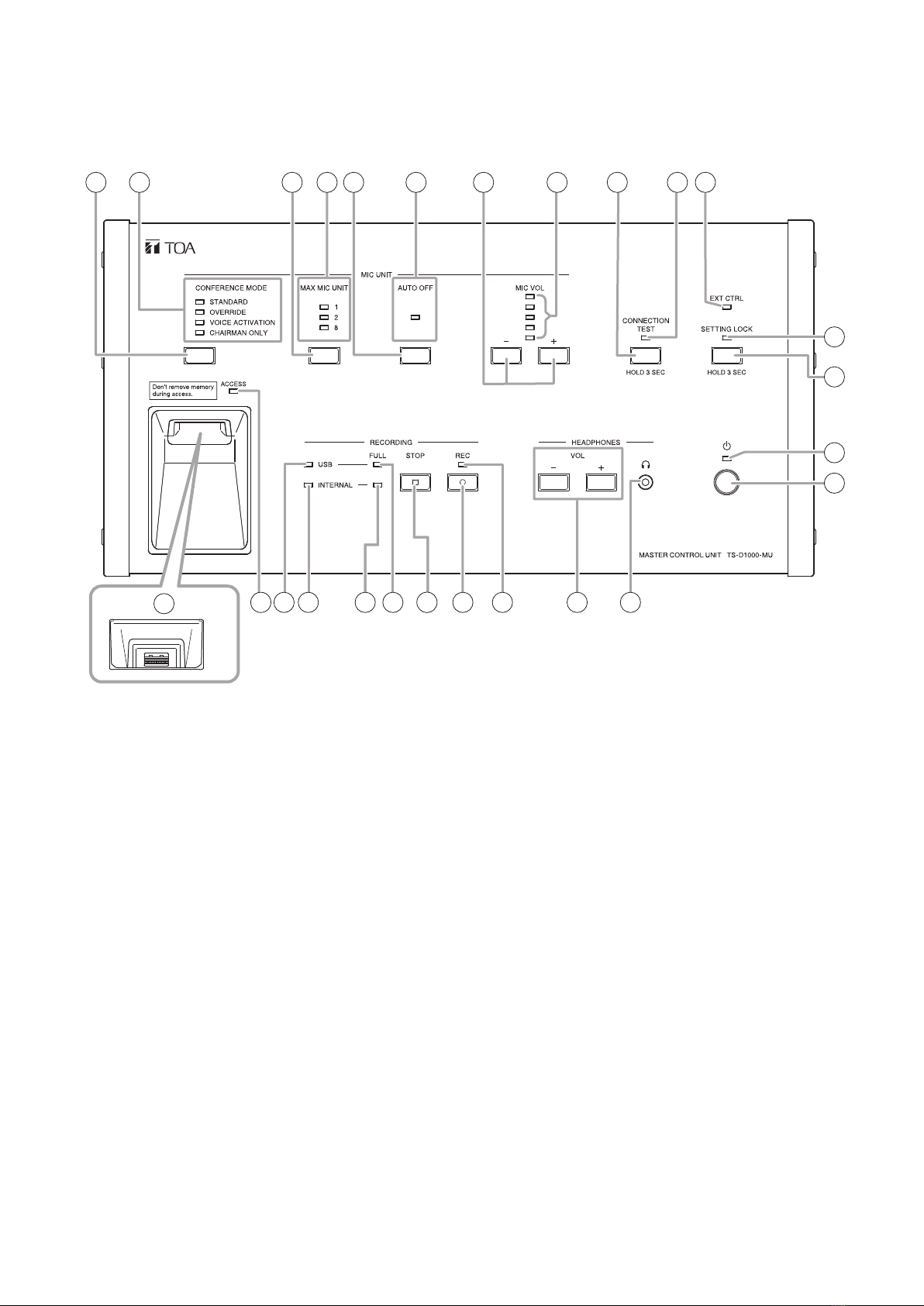
8. Mic auto-off indicator (green)
Lights when Mic auto-off is enabled, and
extinguishes when disabled.
Note
Factory preset to Disabled.
9.MonitorvolumecontrolKeys(−,+)
[−]: Pressing this key reduces the Conference
unit’s monitor speaker volume.
[+]: Pressing this key increases the Conference
unit’s monitor speaker volume.
10. Monitor volume indicators (Green)
Provide visual indication of the Conference unit’s
monitor sound volume level.
11. Connection test key
Pressing this key for 3 seconds or more provides
conrmation of a connection to the Conference
unit. Pressing the key again for 3 seconds or
more terminates the Connection test function.
(See "Connection Test" on p. 30.)
12. Connection test indicator (Orange)
Lights when Conference unit connection test is
enabled and extinguishes when nished.
13. External control indicator (Orange)
Lights when put in centralized control mode using
special-order software.
14. Setting lock indicator (Orange)
Lights when the Setting lock function is enabled,
and extinguishes when setting adjustment can be
performed.
15. Setting lock key
Press this key for 3 seconds or more when
disabling Master control unit key operation to
avoid mistaken operation. ("Setting Lock" on p.
35.)
16. USB memory device port
Insert a USB memory device into this port for
recording. For information on compatible USB
memory device types, please refer to "Usable
USB memory devices" on p. 19.
Note
Internal memory recording is disabled whenever
a USB memory device is inserted into this port.
17. Access indicator (Green)
Remains continuously lit until a compatible USB
memory device is inserted into the USB memory
device port (16). Also remains lit during recording
to the USB memory device.
Note
Do not remove the USB memory device or turn
OFF the power while this indicator is lit.
18. USB memory device indicator (Green)
Lights when the inserted USB memory device is
ready for recording.
19. Internal memory indicator (Green)
Lights when a USB memory device is not inserted
in the USB memory device port to indicate that
recording can be made to internal memory.
20. Internal memory remaining capacity warning
indicator (Orange)
Flashes whenever the internal memory’s
remaining available recording time falls to less
than one hour. Continuously lights to indicate that
no internal memory recording time remains.
21. USB memory device remaining capacity
warning indicator (Orange)
Flashes whenever the USB memory device’s
remaining available recording time falls to less
than one hour. Continuously lights to indicate that
no USB memory device recording time remains.
22. Recording STOP key
Press this key to stop recording.
23. Recording START key
Press this key to start recording.
24. Recording status indicator (Red)
Remains lit during recording.
25.Headphonevolumecontrolkeys(−,+)
[−]: Pressing this key reduces the headphone
sound volume.
[+]: Pressing this key increases the headphone
sound volume.
26. Headphone jack (Mini-Jack)
Connect any compatible monaural headphone to
this jack.
If the headphone is disconnected, headphone
sound volume will revert to the factory default
setting (−10 dB). Restarting the unit’s power will
also cause the sound volume to revert to the
default setting (−10 dB).

9
[Rear]
28 29 31 32
33
30
35
27
34 36 37
27. Cable clamp
Route the power cable through this clamp to
prevent the AC adapter plug from accidentally
being disconnected.
28. Signal ground terminal
When connection of an external device to the TS-
D1000-MU results in the generation of audible
noise, connect this terminal to the Signal ground
terminal of the external device. Noise output
should be greatly reduced.
Note
This is not a protective ground connection.
29. DC inlet
Insert the power plug from the unit’s supplied AC
adapter into this inlet.
30. Conference unit connection terminal
RJ45 x 2
Connects to the Conference unit by way of a
Cat5e STP LAN cable. Up to 16 conference units
can be daisy chain connected to each terminals.
31. Sub control unit connection terminal
RJ45
Connects to a maximum of 5 Sub-Control units by
way of a Cat5e STP LAN cable. If 5 Sub-Control
units are connected, up to 246 Conference units
can be connected to the system.
32. Network connection terminal
RJ45
Connects the PC to the network by way of a Cat5e
STP LAN cable.
• 10 BASE-T/100BASE-TX indicator (Orange)
Extinguishes when a 10BASE-T network is
connected to the TS-D1000-MU, and lights
when a 100BASE-TX network is connected.
• LINK/ACT indicator (Green)
Lights when the TS-D1000-MU is connected to
a network and ashes during data transmission/
reception.
33. Recording output terminals
(−10 dB*, 10 kΩ, unbalanced, RCA pin jack x 2)
Connect to external recording devices, such as
IC recorders. The same sound output is delivered
to both jacks so that simultaneous recordings can
be made using two recording devices.
34. Line output terminal
(−10 dB*, 10 kΩ, unbalanced, phone jack)
Connects to a PA amplier or other public address
device.
35. Equalizer connection terminals
(−10 dB*, 10 kΩ, unbalanced, RCA pin jack x 2)
Connect to an external processor, such as a
feedback suppressor (FBS). Depending on the
status of the input and output terminals, sound
routing and internal FBS ON/OFF status are
automatically switched.
[When connected to an external processor]
When an external processor is connected to
these SEND and RETURN terminals, the internal
FBS circuit is switched OFF.
[When not connected to an external processor]
When no external processor is connected to
these SEND and RETURN terminals, the internal
FBS circuit remains ON.
36. Video conference system connection terminals
(−10 dB*, 10 kΩ, unbalanced, RCA pin jack x 2)
Connect to external devices such as a video
conference system. Mix-minus function eliminates
unit-generated signals from the output.
37. Microphone input terminal
(−54 dB*, 600 Ω, unbalanced, phone jack)
Connects to a wired microphone.
* 0 dB = 1 V
LINK/ACT indicator
10BASE-T/
100BASE-TX indicator

10
1
5.2. TS-D1000-SU Sub Control Unit
[Front]
[Rear]
2
345 6
1. Power indicator (White)
Lights when power is switched ON.
This indicator interlocks with the Master control
unit’s power switch operation when the Master
control unit and the supplied AC adapter are
connected to the Sub control unit.
2. Signal ground terminal
When connection of an external device to the TS-
D1000-SU results in the generation of audible
noise, connect this terminal to the Signal ground
terminal of the external device. Noise output should
be greatly reduced.
Note
This is not a protective ground connection.
3. Cable clamp
Route the power cable through this clamp to
prevent the AC adapter plug from accidentally
being disconnected.
4. DC inlet
Insert the power plug from the unit’s supplied AC
adapter into this inlet.
5. Conference unit connection terminals
RJ45 × 3
Connect conference units to these terminals using
CAT5e STP LAN cables. Up to 16 Conference units
can be daisy chain connected to each terminal.
6. Sub-control unit connection terminals
RJ45 × 2
Connect the Master control unit or other Sub
control units to these terminals using CAT5e STP
LAN cables.
Tip
Either terminal may be used for connection.

11
5.3. TS-D1000-EX Extension Unit
[Top] [Rear]
1
22
34
1. Power indicator (Green)
Lights when power is switched ON.
This indicator interlocks with the Master control
unit’s power switch operation when the Master
control or the Sub control unit, and the supplied AC
adapter are connected to the Extension unit.
2. Mounting holes
Mounting holes for 3 mm (0.12") diameter screws.
Use these holes when attaching the unit to a wall
or other surface.
Note
Please note that the mounting screws themselves
are not supplied with the unit.
3. Conference unit connection terminals
RJ45 × 2
When extending the distance between two
Conference units, connect to either of these
terminals using a CAT5e STP LAN cable.
Tip
Either terminal may be used for connection.
4. DC inlet
Insert the power plug from the unit’s supplied AC
adapter into this inlet.

12
5.4. TS-D1000-CU Chairman Unit
[Top]
1
2 23 54
6
7
1. Monitor speaker
Speech signals from other Conference units and
other audio signals from the Master control unit are
output from this speaker.
Use the right-side Monitor volume control (10)
to adjust the volume. The sound volume of the
monitor speaker is attenuated whenever the unit is
being used for speaking.
Tip
Speaker output can be muted by way of browser
setting.*
2. Speech indicator (Red)
Remains lit while the microphone is in use (during
speech).
3. Talk key
When this key is pressed, both the Speech indicator
(2) and the Microphone in-use indicator (7) light,
and the microphone turns on. Pressing this key
again turns off both indicators and the microphone.
4. Priority speech key
Gives speaking priority to the current speaker.
When this key is used for speech, no other delegate
units can be used. Sound from both external
microphone and video conference inputs are also
muted. The key has 2 different operating modes,
PTT mode and ALT.
Factory preset to PTT mode.
PTT mode: Microphone turns ON only while the
Talk key is pressed.
ALT mode: Microphone turns ON when the
Talk key is pressed, and OFF when
pressed again.
If Chime is set to sound, a chime tone sounds when
the key is pressed.
Factory preset to ON.
A browser can be used to set key operation and
chime volume.
For more information regarding key operation
and its actions, please refer to "Initiating Priority
Speech" on p. 17.
5. Power indicator (White)
Lights when the power is switched ON.
6. Microphone
Use either the TS-D1000-M1 Standard microphone
or TS-D1000-M2 Long microphone.
7. In-use indicator (Red)
Lights when the microphone is turned on (for
speech).
* For details, please refer to the separate Instruction
Manual (Browser Settings), which can be
downloaded from the TOA DATA Library (https://
www.toa-products.com/international/).
Note: No microphone is supplied with the TS-D1000-CU.

13
10. Monitor volume control
Adjusts the output volume of the monitor speaker
and right-side earphone output.
11. Earphone Jacks
Connect earphone to this jack (mini-jack).
Note
A earphone jack is located on both the left and
right side panels.
Monitor speaker output is muted only when the
earphone plug is inserted into the right-side
earphone jack.
12. Earphone volume control
Adjusts the output volume of the left-side earphone
output.
[Bottom]
10 11
12
11
[Right side]
[Left side]
(Cover)
(The figure which took off the cover)
8
99
8. Connection terminal cover
Detach this cover when connecting Conference
units to the Conference unit connection terminals
(9). After completing connection, replace the cover
where it was.
9. Conference unit connection terminals
RJ45 x 2
Connect these terminals to the Conference
unit connection terminal of the TS-D1000-MU
Master control unit, a TS-D1000-SU Sub control
unit, a TS-D1000-EX Extension unit or another
Conference unit using CAT5e STP LAN cables.
Tip
Either terminal may be used for connection.

14
5.5. TS-D1000-DU Delegate Unit
[Top]
1
2 3 24
5
6
1. Monitor speaker
Speech signals from other Conference units and
other audio signals from the Master control unit are
output from this speaker.
Use the right-side Monitor volume control (9)
to adjust the volume. The sound volume of the
monitor speaker is attenuated whenever the unit is
being used for speaking.
Tip
Speaker output can be muted by way of browser
setting.*
2. Speech indicator (Red)
Remains lit while the microphone is in use (during
speech).
3. Talk key
When this key is pressed, both the Speech indicator
(2) and the Microphone in-use indicator (6) light,
and the microphone turns on. Pressing this key
again turns off both indicators and the microphone.
4. Power indicator (White)
Lights when the power is switched ON.
5. Microphone
Use either the TS-D1000-M1 Standard microphone
or TS-D1000-M2 Long microphone.
6. In-use indicator (Red)
Lights when the microphone is turned on (for
speech).
* For details, please refer to the separate Instruction
Manua l (B rows er S et t ing s), w hic h can be d ow nload ed
from the TOA DATA Library (https://www.toa-
products.com/international/).
Note: No microphone is supplied with the TS-D1000-DU.

15
9. Monitor volume control
Adjusts the output volume of the monitor speaker
and right-side earphone output.
10. Earphone jacks
Connect earphones to this jack (mini-jack).
Note
A earphone jack is located on both the left and
right side panels.
Monitor speaker output is muted only when the
earphone plug is inserted into the right-side
earphone jack.
11. Earphone volume control
Adjusts the output volume of the left-side earphone
output.
[Bottom]
(Cover)
(The figure which took off the cover)
7
8 8
10
9
11
10
[Right side]
[Left side]
7. Connection terminal cover
Detach this cover when connecting Conference
units to the Conference unit connection terminals
(8). After completing connection, replace the cover
where it was.
8. Conference unit connection terminals
RJ45 x 2
Connect these terminals to the Conference
unit connection terminal of the TS-D1000-MU
Master control unit, a TS-D1000-SU Sub control
unit, a TS-D1000-EX Extension unit or another
Conference unit using CAT5e STP LAN cables.
Tip
Either terminal may be used for connection.

16
6. CONFERENCE SYSTEM OPERATION
When the Voice activation conference mode is selected, no further operation of the Conference unit is required.
(See p. 31.)
6.1. Requesting Permission to Speak
Step 1. Press the Talk key.
Both the Speech and the microphone’s In-use indicators light
up, and the microphone turns on.
Notes
• The microphone cannot be turned on while the Chairman unit
has Priority speech enabled (the next page), even if the Talk
key is pressed.
• In the case of the TS-D1000-DU Delegate unit, the microphone
may not turn on, even if the Talk key is pressed, due to Max.
open mic No. restrictions being enabled (p. 32).
• Up to two Chairman units can always be used for speaking,
regardless of Max. open mic No. restrictions (Priority speech
excepted).
Tips
• Monitor speaker sound volume is automatically attenuated
whenever both the Speech and the microphone’s In-use
indicators are lit.
• Speaker volume can also be muted in the browser settings.
For details, please refer to the separate Instruction Manual
(Browser Settings), which can be downloaded from the TOA
DATA Library (https://www.toa-products.com/international/).
Step 2. Speak.
Step 3. After speaking is nished, press the Talk key again.
Both the Speech and the microphone’s In-use indicators
extinguish, returning the monitor speaker output to its original
volume.
[TS-D1000-DU Delegate unit example]
Talk key
Speech indicator
In-use indicator
TS-D1000-M1
Standard microphone
or
TS-D1000-M2
Long microphone

17
6.2. Initiating Priority Speech (TS-D1000-CU Chairman Unit Only)
Only the TS-D1000-CU Chairman unit has Priority control over speaking functions. Even when a speech is in
progress among Conference units, the Chairman unit can terminate the speech and supersede other speakers.
Chairman unit priority speech activation can differ depending on whether operation is set to PTT (see below)
or ALT (the next page). Priority speech operation can be changed by browser. For details, please refer to the
separate Instruction Manual (Browser Settings).*
Note
Chairman unit priority speech cannot be activated when the Conference mode is set to Voice activation.
(See "Conference Mode Setting" on p. 31).
6.2.1. When priority speech activation is set to PTT (factory default setting)
Step 1. Speak while holding down the Priority speech key.
Both the Speech and the microphone’s In-use indicators light,
and the microphone turns on.
A single-tone chime is sounded at all other Conference units,
indicating that the Delegate units cannot be used for speaking.
Chime ON/OFF settings can be changed via the browser
(factory default setting: ON).
For details, please refer to the separate Instruction Manual
(Browser Settings).*
Notes
• During Chairman unit priority speech, sound output from
connected wired microphones and the video conference
system are muted.
• In the case of systems congured with multiple Chairman
units, if one Chairman unit has initiated Priority speech, other
Chairman units cannot initiate Priority speech, even if their
Priority speech keys are pressed.
Tips
• Monitor speaker sound volume is attenuated when both
Speech and the microphone’s In-use indicators are lit.
• Monitor speaker volume can be muted in the browser settings.
For details, please refer to the separate Instruction Manual
(Browser Settings).
Step 2. Release the Priority speech key after speaking is completed.
Both the Speech and the microphone’s In-use indicators
extinguish, returning monitor speaker output to its original
volume.
Note
Terminated Conference units do not automatically revert to their
previous speaking modes after Priority speech is terminated.
In such cases, rst press the Talk key again to cause both the
Speech and the microphone’s In-use indicators to light, then
begin speaking.
* Can be downloaded from the TOA DATA Library (https://www.toa-products.com/international/).
TS-D1000-M1
Standard microphone
or
TS-D1000-M2
Long microphone
In-use indicator
Priority speech key
Speech indicator

18
6.2.2. When priority speech activation is set to ALT
Step 1. Press the Priority speech key.
Both the Speech and the microphone’s In-use indicators light,
and the microphone turns on.
A single-tone chime is sounded at all other Conference units,
disabling speech from the Delegate units.
The chime can be turned ON or OFF in the browser settings
(factory default setting: ON). For details, please refer to the
separate Instruction Manual (Browser Settings).*
Notes
• Monitor speaker sound volume is attenuated when both
Speech and the microphone’s In-use indicators are lit.
• Monitor speaker volume can be muted in the browser settings.
For details, please refer to the separate Instruction Manual
(Browser Settings).*
Step 2. Speak.
While speaking in Priority speech mode, no Delegate units can
speak.
Notes
• During Chairman unit Priority speech, sound output from
connected wired microphones and the video conference
system are muted.
• In the case of systems congured with multiple Chairman
units, if one Chairman unit has initiated Priority speech, other
Chairman units cannot use Priority speech, even if their
Priority speech keys are pressed.
Step 3. After speaking is nished, press the Priority speech key again.
Both the Speech and the microphone’s In-use indicators
extinguish, returning monitor speaker output to its original
volume.
Note
Terminated Conference units do not automatically revert to their
previous speaking modes after Priority speech is terminated.
In such cases, rst press the Talk key again to cause both the
Speech and the microphone’s In-use indicators to light, then
begin speaking.
* Can be downloaded from the TOA DATA Library (https://www.toa-products.com/international/).
TS-D1000-M1
Standard microphone
or
TS-D1000-M2
Long microphone
In-use indicator
Priority speech key
Speech indicator

19
7. USING THE RECORDING FUNCTION
The TS-D1000-MU Master control unit is equipped with a recording function, making it possible to create sound
source les by recording conference dialog and the like to a commercially available USB memory device. The
TS-D1000-MU is also equipped with internal memory for recording operations, and allows recording even when
abnormalities arise with the USB memory device.
Note
Only recording can be performed by the TS-D1000-MU. Use a PC to reproduce, delete or copy sound source
les.
7.1. Notes on Use
Important
Avoid removing the USB memory device during recording. If removed, the USB memory device might not
continue to function properly, or data could be lost.
• The USB memory device cannot be formatted by the TS-D1000-MU.
• Only USB memory devices can be inserted into the USB memory port. Inserting other USB devices could
result in operational failure.
• Move the sound source le created in the USB memory device to a PC or other device without saving it to the
USB memory device.
• When inserting or removing the USB memory device, do not apply unreasonable force to the port. Failure to
observe this instruction could lead to failure of the TS-D1000-MU or damage to the PC or other devices.
• Ensure that the USB memory device is removed when moving the TS-D1000-MU from one place to another.
Moving the TS-D1000-MU with such devices inserted could cause failure to the TS-D1000-MU or damage to
the USB memory device.
• Be sure to back up recorded internal memory sound source data to a PC or other device, as data could be
lost due to the TS-D1000-MU’s failure or faulty operation.
7.2. Usable USB Memory Devices
• USB memory device (ash drive) with a capacity of up to 32 GB.
• Compatible with USB 2.0 devices.
• When using a USB memory device with the TS-D1000-MU for the rst time, format it with a PC before using.
Formatting conditions are as follows:
File system: FAT32
Allocation unit size: At least 4KB
• Insert the USB memory device into the PC and perform error checking before use.
• Ensure that the USB memory device is ONLY used with the TS-D1000-MU, and avoid using it for other
purposes.
• USB memory devices having other specialized functions, such as security functions, cannot be used with the
TS-D1000-MU
• There may be cases in which a USB memory device cannot be used with the TS-D1000-MU, depending on
the drive’s attributes or recording conditions.

20
7.3. Sound Source File Specifications and Filenames
Notes
• All sound inputs are mixed and recorded.
• Noise may be generated, depending on the contents or volume settings of the input sound source. If annoying,
adjust the sound volume of the conference unit or external sound source.
Shown below are specications and lename format for recorded sound source les:
• Specications
Recording format: MP3 (monaural)
Sampling frequency: 32 kHz
Bit rate: 128 kbps
Maximum le size: 54.9 MB (recording time: 1 hour)
Tips
• Since the sound source le is automatically divided each time one hour elapses, the
above is the maximum size.
• The size of the internal memory is 1 GB, allowing recordings to be made for a total of
approximately 18 hours.
• Filename format
A lename indicating the Year, Month, Date, Hour, Minute and Second of the time that the recording was
started is automatically assigned to each le as follows:
Sound source lename: YYYYMMDD_HHMMSS.mp3
Example
In the case of a recording started at precisely 10 o’clock AM on January 1, 2020,
the lename “20200101_100000.mp3” is assigned when the recording is stopped.
When a recording is continuously made for longer than one hour, the sound source le will automatically be
divided whenever one hour passes, and the resulting le saved under a newly assigned lename.
[Time Setting and Confirmation]
The recording start time included in the sound source lename corresponds to the Master control unit’s internal
clock. The internal clock can be set via network using a PC browser.
For details, please refer to the separate Instruction Manual (Browser Settings), which can be downloaded from
the TOA DATA Library (https://www.toa-products.com/international/).
Other manuals for TS-D1000 Series
1
This manual suits for next models
5
Table of contents
Other Toa Conference System manuals