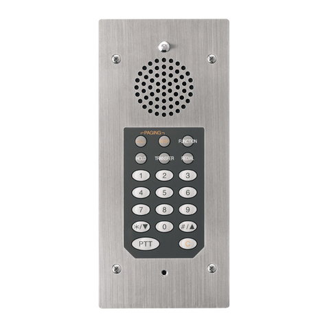
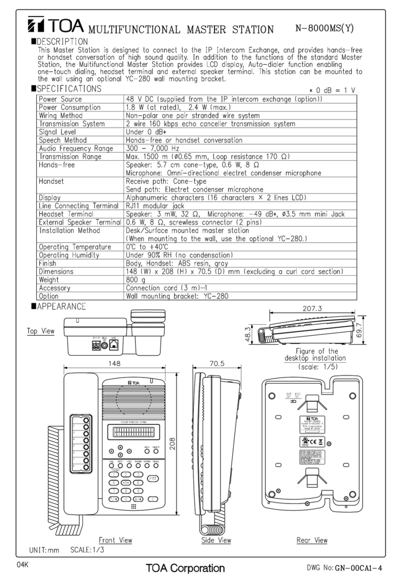
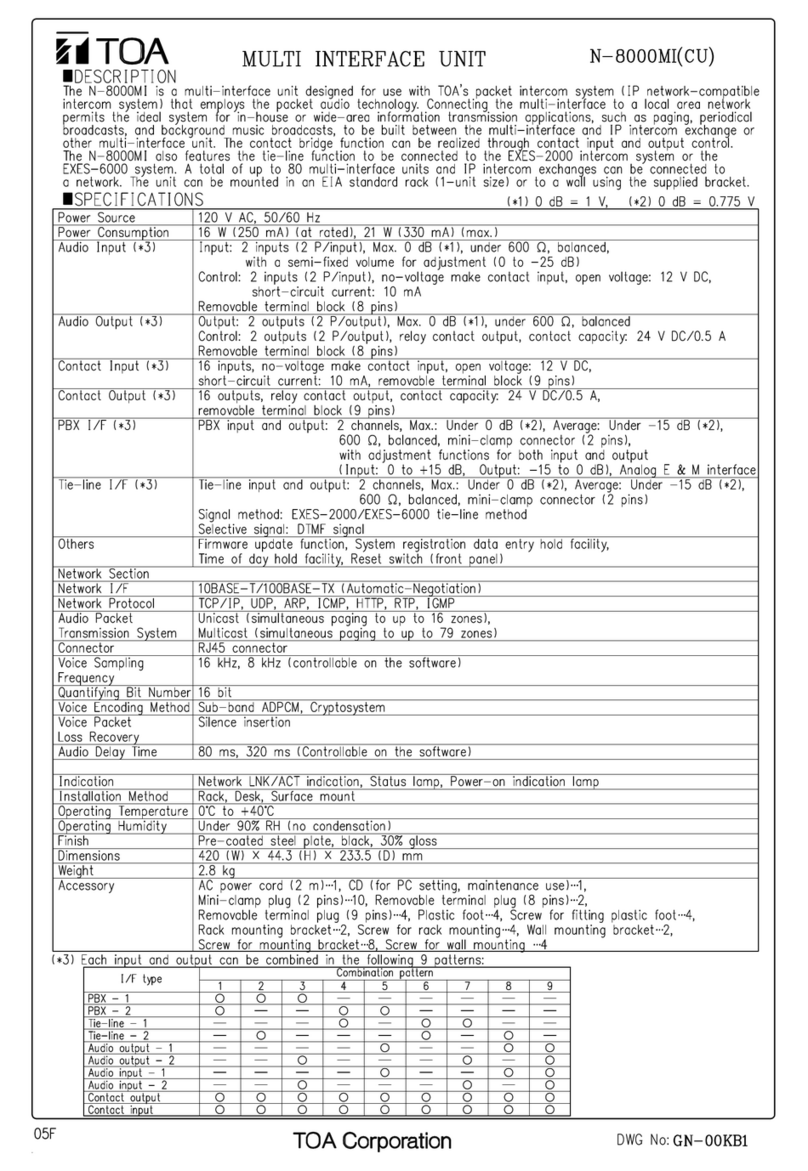
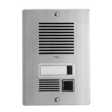
Toa RS-410EC e User manual

TOA Electronics Europe GmbH
Thank you for purchasing TOA's Intercom Station.
Please carefully follow the instructions in this manual to ensure long, trouble-free use of your equipment.
Note: For operation of the units, refer to the N-8000 series operating instructions.
OPERATING INSTRUCTIONS
Intercom Emergency Substation
RS-410EC e

2
When Installing the Unit
• Do not expose the unit to rain or an environment
where it may be constantly splashed by water
or other liquids, as doing so may result in fire or
electric shock.
• Use the unit only with the voltage specified on
the unit. Using a voltage higher than that which is
specified may result in fire or electric shock.
• Install the unit in a matching position. The unit
shall neither be installed in a position where the
calls can be released accidentially nor in a position
which the target group cannot access.
• The station shall be connected to the system's
power with a protective earthing connection.
• Mount the unit in a viable mounting plate or wall
whose structure is matching with the weight of the
substation.
• Fix the unit at the wall so that it can neither be
peeled off nor fall off.
When the Unit is in Use
• Should the following irregularity be found during
use, immediately switch off the system's power and
contact your nearest TOA dealer. Make no further
attempt to operate the unit in this condition as this
may cause fire or electric shock.
· If you detect smoke or a strange smell coming
from the unit.
· If water or any metallic object gets into the unit
· If the unit falls, or the unit case breaks
· If the power supply cord is damaged (exposure of
the core, disconnection, etc.)
· If it is malfunctioning (no tone sounds.)
• To prevent a fire or electric shock, never open nor
remove the unit panel as there are high voltage
components inside the unit. Refer all servicing such
as modification inside the unit to qualified service
personnel.
• Do not touch a plug during thunder and lightning,
as this may result in electric shock.
When Installing the Unit
• When unplugging be sure to grasp the plug; never
pull on the cord itself. Operating the unit with a
damaged cord may cause a fire or electric shock.
• Avoid installing the unit in dusty locations or in
locations exposed to the direct sunlight, near the
heaters, or in locations generating sooty smoke
or steam as doing otherwise may result in fire or
electric shock.
• To avoid electric shocks, be sure to switch off the
system's power while connecting.
When the Unit is in Use
• Do not operate the unit for an extended period of
time with the sound distorting. This is an indication
of a malfunction, which in turn can cause heat to
generate and result in a fire.
1. SAFETY PRECAUTIONS
• Before installation or use, be sure to carefully read all the instructions in this section for correct and safe
operation.
• Be sure to follow all the precautionary instructions in this section, which contain important warnings and/or
cautions regarding safety.
• After reading, keep this manual handy for future reference.
Safety Symbol and Message Conventions
Safety symbols and messages described below are used in this manual to prevent bodily injury and property
damage which could result from mishandling. Before operating your product, read this manual first and
understand the safety symbols and messages so you are thoroughly aware of the potential safety hazards.
WARNING
Indicates a potentially hazardous situation which, if mishandled, could
result in death or serious personal injury.
Indicates a potentially hazardous situation which, if mishandled, could
result in moderate or minor personal injury, and/or property damage.
WARNING
CAUTION
CAUTION
The lighting flash with arrowhead symbol,
within an equilateral triangle, is intended
to alert the user to the presence of
uninsulated "dangerous voltage" within
the product's enclosure that may be of sufficient
magnitude to constitute a risk of electric shock to
persons.

3
2. GENERAL DESCRIPTION
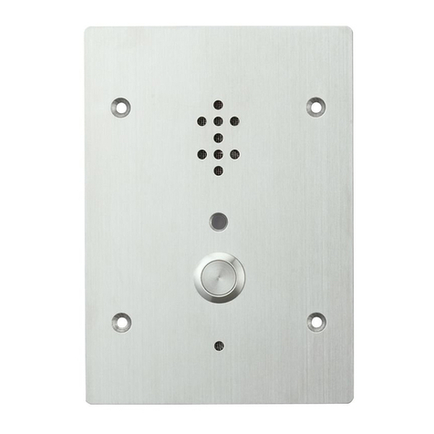
The RS-410EC e is an Information-/Emergency-Call Intercom substation, to be connected to the N-8400RS
4-wire Substation Interface Unit.
The substation is designed to be used in public areas under rough environmental conditions. It is impact proof
(IK10) and weather resistant (IP65) and therefore vandal proof. The operating temperature ranges from -10°C
up to + 50°C.
The front plate is made of brushed aluminum. The red emergency call button (illuminated if pressed) is
protected by a pane and can get highest call priority if programmed via Selective Response Mode + Priority
5. The metallic info-call button gets lower priority (1-4) and is intended for informational calls. It features 2
different programable call targets each one individual target per button.
Emergency calls are listed in position one of the call queue on the master station (N-8000MS/N-8600MS) and
in addition are signalled by a sound.
3. FEATURES
• Two different priotity-levels: Emergency and standard calls.
• Emergency calls can be forwarded to a security post.
• Vandal Proof.
• IK 10 impact tested.
• IP 65 weather resistant.
• Easy to use.
4. HANDLING PRECAUTIONS
• Install the unit in locations where the temperature is between –10 and +50°C and the moisture is less than
90%RH (no dew condensation must be formed).
• To clean wipe with a dry cloth. When the unit gets very dirty, use a cloth damped in a neutral cleanser.
Never use benzene, thinner, alcohol, or chemically-treated cleaning cloth because such volatile liquids could
deform or discolor the unit.

1
2
3
4
5
6
1 2 3 4 E
8
9
7
4
6. NOMENCLATURE AND FUNCTIONS
[Front]
1. Torx Screw
Use Torx Screwdriver: Size T10 to screw or to
unscrew the substation.
2. Speaker
Outputs call tones and used for hands-free
conversations. Protected against attacks by
means of wires or fluids.
3. Operation Indicator
Lights as long as the unit is connected to the
exchange.
4. Emergency Push Button
The button is protected by a protective pane.
In case of emergency this pane has to be
smashed.
5. Standard Push button
Used to call the pre-programmed master station.
(See p. 8)
6. Microphone
Used for hands-free conversation. For both
Emergency and Standard conversation. The
microphone will be opened after the call was
received.
7. Connection terminal [Earth]
Connects to Earth
8. Connection terminal [1-4]
Connects to the N-8400RS exchange. (Terminal
block) (See p. 7)
9. Ground terminal
Connects to Ground of OW-101
[Rear]

or
Duplex conversations
or
Duplex conversations
5
7. OPERATION
7.1. Calling
7.1.1. Emergency calls
Step 1 Smash the pane.
Step 2 Push the red button.
Then the button blinks
Step 3 After the called party responds the push button lights
and the emergency conversation can start.
Notes
The RS-410EC e processes one call at a time. Further pressing of a button
does not direct the call to another station. After the call has been proceeded
and finished a new call can be processed.
A smashed pane is to be replaced by a new pane (spare part).
7.1.2. Standard calls
The pre-programmed master station can be called by pressing
the lower station's call button.
Note
The master station to call to has been programmed (See page 8).
Programming can be performed by the N-8000 software program.
Push the button
Talk when the button lights
Push the button
Talk after the attention tone
HELP

RS-410EC
Wall
surface
OW-101
RS-410EC
Wall
surface
Wall
surface
IW-101
6
Torx Screws
8. Installation
8.2. Installation of the Substation RS-410EC e
8.1. Back Box
Mount the substation to the IW-101 electrical box if mounted in the wall.
Mount the substation to the OW-101 if mounted on the wall.
Note
Tightly seal all panel edges of the OW-101.
Notes
Make sure to seal the edges of both the panel and the box's rear surface when installing the RS-410EC
outdoors or in locations where it gets splashed with water.
Recommended Back Boxes for RS-410EC are either for ush-mounting IW-101 or for surface-mounting
OW-101
Provide a weep hole at the bottom of the mounting box to permit water to drain off.
To insert cable from top- or bottom-side of the box a cable gland must be installed to avoid damages such
as bending or rub through. Consider to use a cable gland that meets the desired water + dust protection.
Drill a hole according to the specications of the cable gland to be used.
Flush-Mounting:
The front edge of the IW-101 must not be more than 3mm away from the surface of the wall.
Note
Tightly seal all
panel edges of the
RS-410EC
e
e

3
2
4
7 mm
7
9. Connection
Wiring
Take care that earth terminal "E" will be connected to earth.
Make sure to connect the frame ground terminal at the rear side to ground.
1
2
3
4
Earth
9.1. Terminal plug connection
Step 1. Strip a cable jacket of approx. 7 mm from the cable end.
For cables, refer to p. 10, type of cable.
Note
Do not solder plate on exposed inner cables when using a stran-
ded wire.
Step 2. Loosen the terminal screws and insert the cables.
Step 3. Tighten the terminal screws securely.
Notes
• Tug lightly on the cable to be sure that it does not pull free. If the cable pulls free, loosen the terminal
screw again and reconnect from Step 2.
• Use the screwdriver appropriate to the screws tightened into the terminal plug.
Step 4. (Removable terminal plug only)
Insert the wired terminal plug into the terminal block or the pin header.
Connector
Tighten
Terminal block
Removable terminal plug (sup-
plied with the RS-410EC)
G 1 2 3 4 E
Ground

*
*
*
8
10. PROGRAMMING
The RS-410EC e shall be programmed via latest N-8000 Setting Software and it shall be registered via the
Model Name: RS-442.
The system mode shall be “Selective Response”
10.1 Programming the LED of emergency push button (lit if the emergency button was pressed)
Activate Calling Station Indication -> During call and talk
10.2 Programming the Call Targets and Priority Settings
see next page

150
45
114
247
221
153 141
49
49
114 114
249
240
221
214
OW-101 IW-101
9
11. DIMENSIONAL DIAGRAM
Unit: mm
[FRONT VIEW] [BOTTOM VIEW]
RS-410EC e
Priority:
Call 1 = 1 (low priority)
Call 2 = 5 (emergency call / high priority)
Call 3 = Not available
Call Master
Call 1 = Call Target for Standard Push Button
Call 2 = Call Target for Emergency Push Button
Call 3 = Not available

12. SPECIFICATIONS
Note: Change of design and specications without prior notice possible.
• Options
Surface-mount box: OW-101 ................................................... 1
Flush-mount box: IW-101 ......................................................... 1
Model RS-410EC e
Rated Input 1 W
Audio Frequency Range 300Hz – 7kHz
Speech Method Hands-free conversation
Hands-free Speaker: 3,5cm (1.38“) cone-type, maximum output 0,5W, 8Ω
Microphone: Omni-directional electret condenser microphone
Push-button Standard Momentary, stainless steel, silver
Push-button Emergency
Momentary, red (blinks red during calling, lights during conversation)
Description Emergency
Protective pane
Operation Indicator 1 LED
Wiring Twisted pair cables (2x pair)
Transmission Range
1km / Ø 0,5mm (AWG24)
1,5km / Ø 0,65mm (AWG22)
2km / Ø 0,9mm (AWG19)
Installation Method Flush-mount / Surface-mount
Housing Protection IEC 62262: IK10
Dust/ Water Protection EN 60529: IP 65. (panel edges must be sealed at installation)
Operating Temperature -10°C to 50 °C
Operating Humidity Under 90 % RH (condensation free)
Finish Front plate: Aluminum
Call-buttons: Steel
Dimensions 150 (W) x 247 (H) x 45 (D) mm
Weight 0.6 kg
Traceability Information for Europe (EMC directive 2004/108/EC)
Manufacturer:
TOA Electronics Europe GmbH
Suederstrasse 282, 20537 Hamburg, Germany
Authorised representative
TOA Electronics Europe GmbH
Suederstrasse 282, 20537 Hamburg,
Germany
http://www.toa.de/
833TEERZ1603b
Table of contents
Other Toa Intercom System manuals
Popular Intercom System manuals by other brands

Slinex
Slinex Design Direct Series user manual

Panasonic
Panasonic VL-V591 Installation and operation guide

Bpt
Bpt HEP/306 installation instructions

Esse-ti
Esse-ti Rubino user manual

urmet domus
urmet domus CROTHE VIDOORA Installation and operating instructions

WHD
WHD VoiceBridge Standard&Bluetooth Kit manual