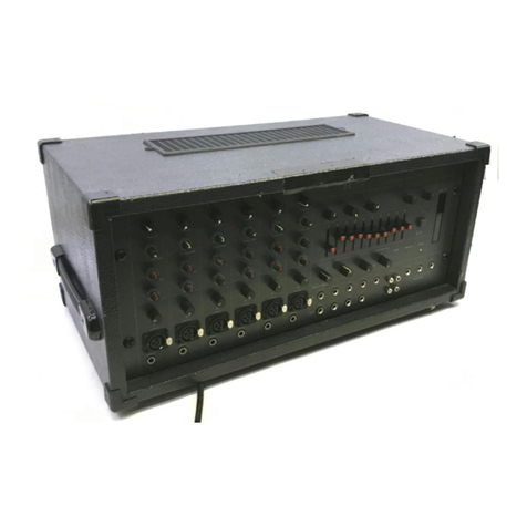
Toa M-124FX-EB User manual

CTRL ROOM SOURCE
OPERATING INSTRUCTIONS
12CH MIXER WITH EFFECT AND USB
M-124FX-EB
PC
/
Thank you for purchasing TOA's 12ch Mixer With Effect And USB.
Please carefully follow the instructions in this manual to ensure long, trouble-free use of your equipment.
1. IMPORTANT SAFETY INSTRUCTIONS .... 2
2. SAFETY PRECAUTIONS ........................... 3
3. GENERAL DESCRIPTION ......................... 5
....... 5
4. FEATURES ................................................. 5
5. NOMENCLATURE AND FUNCTIONS
6.
POWER AND
LEVEL ADJUSTMENT
7. CONNECTIONS ........................................ 12
...... 11
CONNECTIONS
8 EXAMPLE OF EXTERNAL EQUIPMENT
........................................ 13
9. DSP DIGITAL EFFECTS PRESET LIST ... 14
11. BLOCK DIAGRAM ................................... 15
10. RACK MOUNTING ................................... 14
12. SPECIFICATIONS . 16
13.
14. ARABIC IMPORTANT SAFETY
INSTRUCTIONS ........................................ 17
DIMENSIONAL DIAGRAM ....................... 16
...................................
TABLE OF CONTENTS

1. IMPORTANT SAFETY INSTRUCTIONS
• Read these instructions.
• Keep these instructions.
• Heed all warnings.
• Follow all instructions.
• Do not use this apparatus near water.
• Clean only with dry cloth.
• Do not block any ventilation openings. Install in accordance with the manufacturer's instructions.
• Do not install near any heat sources such as radiators, heat registers, stoves, or other apparatus (including
amplifiers) that produce heat.
• Do not defeat the safety purpose of the polarized or grounding-type plug. A grounding type plug has two
blades and a third grounding prong. If the provided plug does not fit into your outlet, consult an electrician
for replacement of the obsolete outlet.
• Protect the power cord from being walked on or pinched particularly at plugs, convenience receptacles, and
the point where they exit from the apparatus.
• Only use attachments/accessories specified by the manufacturer.
• Use only with the cart, stand, tripod, bracket, or table specified by the manufacturer,
or sold with the apparatus. When a cart is used, use caution when moving the
cart/apparatus combination to avoid injury from tip-over.
• Unplug this apparatus during lightning storms or when unused for long periods of time.
• Refer all servicing to qualified service personnel. Servicing is required when the apparatus has been
damaged in any way, such as power-supply cord or plug is damaged, liquid has been spilled or objects have
fallen into the apparatus, the apparatus has been exposed to rain or moisture, does not operate normally, or
has been dropped.
INSTRUCTIONS ESSENTIELLES POUR LA SÉCURITÉ
• Lire ces instructions.
• Conserver ces instructions pour référence ultérieure.
• Respecter tous les avertissements.
• Suivre toutes les instructions.
• Ne pas utiliser cet appareil à proximité d'eau.
• Nettoyer uniquement à l'aide d'un chiffon sec.
• Ne pas obstruer les orifices de ventilation. Installer conformément aux instructions du fabricant.
• Ne pas installer à proximité de sources de chaleur telles que des radiateurs, des registres thermiques, des
chaudières ou d'autres appareils (notamment des amplificateurs) produisant de la chaleur.
• Ne pas contourner la fonction de sécurité de la fiche polarisée ou de mise à la terre. Une fiche de mise à
la terre est équipée dedeux broches et d'une troisième pour la mise à la terre. Si la fiche fournie ne
peut être insérée dans la prise électrique souhaitée, consulter un électricien pour faire remplacer cette
dernière.
• Protéger le cordon d'alimentation pour éviter qu'il ne soit piétiné ou pincé, notamment au niveau des fiches,
des prises de courant ou de son point de sortie de l'appareil.
• Utiliser uniquement les accessoires spécifiés par le fabricant.
• Utiliser uniquement avec le chariot, support, trépied, la patte de montage ou la table
spécifiés par le fabricant ou vendus avec l'appareil. En cas d'utilisation d'un chariot,
manipuler la combinaison chariot/appareil pour éviter les blessures dues à un
renversement.
• Débrancher cet appareil pendant les orages ainsi que lorsqu'il reste inutilisé pendant une période prolongée.
• La maintenance de l'appareil doit être confiée à un technicien après-vente qualifié. Une maintenance s'avère
nécessaire si l'appareil est endommagé (au niveau du cordon d'alimentation ou de la fiche), a été mouillé
par un liquide, un objet est tombé à l'intérieur, s'il a été exposé à la pluie ou l'humidité, s'il ne fonctionne pas
normalement ou s'il est tombé.
2
When Installing the Unit
WARNING:
Do not expose the unit to rain or an environment where it may be splashed by water or other
liquids, as doing so may result in fire or electric shock.
Use the unit only with the voltage specified on the unit. Using a voltage higher than that which is specified
may result in fire or electric shock.
Do not cut, kink, otherwise damage nor modify the power supply cord. In addition, avoid using the power
cord in close proximity to heaters, and never place heavy objects -- including the unit itself -- on the power
cord, as doing so may result in fire or electric shock.
Avoid installing or mounting the unit in unstable locations, such as on a rickety table or a slanted surface.
Doing so may result in the unit falling down and causing personal injury and/or property damage.
External wiring connected to the terminals marked with requires installation by an instructed person.
The apparatus shall be connected to a mains socket outlet with a protective earthing connection.
The unit is not suitable for use in locations where children are likely to be present.
L'appareil doit être branché à une prise d'alimentation avec mise à la terre de protection.
The socket-outlet shall be installed near the equipment and the plug (disconnecting device) shall be easily
accessible.
When the Unit is in Use
Should the following irregularity be found during use, immediately switch off the power, disconnect the power
supply plug from the AC outlet and contact your nearest TOA dealer. Make no further attempt to operate the
unit in this condition as this may cause fire or electric shock.
· If you detect smoke or a strange smell coming from the unit
· If water or any metallic object gets into the unit
· If the unit falls, or the unit case breaks
· If the power supply cord is damaged (exposure of the core, disconnection, etc.)
· If it is malfunctioning (no tone sounds.)
To prevent a fire or electric shock, never opennor remove the unit case as there are high voltage
components inside the unit. Refer all servicing to your nearest TOA dealer.
Do not place cups, bowls, or other containers of liquid or metallic objects on top of the unit. If they
accidentally spill into the unit, this may cause a fire or electric shock.
Do not insert nor drop metallic objects or flammable materials in the ventilation slots of the unit's cover, as
this may result in fire or electric shock.
Indicates a potentially hazardous situation which, if mishandled, could
result in death or serious personal injury.
WARNING
2. SAFETY PRECAUTIONS
Before installation or use, be sure to carefully read all the instructions in this section for correct and safe
operation.
Be sure to follow all the precautionary instructions in this section, which contain important warnings and/or
cautions regarding safety.
After reading, keep this manual handy for future reference.
Safety Symbol and Message Conventions
Safety symbols and messages described below are used in this manual to prevent bodily injury and property
damage which could result from mishandling. Before operating your product, read this manual first and
understand the safety symbols and messages so you are thoroughly aware of the potential safety hazards.
The exclamation point within an equilateral triangle is intended to alert the user to the presence of
important operation and maintenance (servicing) instruction in the literature accompanying the
appliance.
Le point d'exclamation à l'intérieur d'un triangle équilatéral avertit l'utilisateur de l'existence
d'instructions d'utilisation et d'entretien (réparation) dans la documentation fournie avec l'appareil.
3

When Installing the Unit
• Never plug in nor remove the power supply plug with wet hands, as doing so may cause electric shock.
• When unplugging the power supply cord, be sure to grasp the power supply plug; never pull on the cord
itself. Operating the unit with a damaged power supply cord may cause a fire or electric shock.
• When moving the unit, be sure to remove its power supply cord from the wall outlet. Moving the unit with the
power cord connected to the outlet may cause damage to the power cord, resulting in fire or electric shock.
When removing the power cord, be sure to hold its plug to pull.
• Do not block the ventilation slots in the unit's cover. Doing so may cause heat to build up inside the unit and
result in fire.
• Avoid installing the unit in humid or dusty locations, in locations exposed to the direct sunlight, near the heaters,
or in locations generating sooty smoke or steam as doing otherwise may result in fire or electric shock.
• To avoid electric shocks, be sure to unplug the unit's power supply cord when connecting speakers.
• Be sure to follow the instructions below when rack-mounting the unit. Failure to do so may cause a fire or
personal injury.
· Install the equipment rack on a stable, hard floor. Fix it with anchor bolts or take other arrangements to
prevent it from falling down.
· When connecting the unit's power cord to an AC outlet, use the AC outlet with current capacity allowable to
the unit.
· No rack-mounting screws are supplied with the unit. Separately prepare the appropriate screws for the
rack.
When the Unit is in Use
• Do not place heavy objects on the unit as this may cause it to fall or break which may result in personal
injury and/or property damage. In addition, the object itself may fall off and cause injury and/or damage.
• Make sure that the volume control is set to minimum position before power is switched on. Loud noise
produced at high volume when power is switched on can impair hearing.
• Do not operate the unit for an extended period of time with the sound distorting. This is an indication of a
malfunction, which in turn can cause heat to generate and result in a fire.
• If dust accumulates on the power supply plug or in the wall AC outlet, a fire may result. Clean it periodically.
In addition, insert the plug in the wall outlet securely.
• Switch off the power, and unplug the power supply plug from the AC outlet for safety purposes when
cleaning or leaving the unit unused for 10 days or more. Doing otherwise may cause a fire or electric shock.
Indicates a potentially hazardous situation which, if mishandled, could
result in moderate or minor personal injury, and/or property damage.
CAUTION
The lighting flash with arrowhead symbol, within an equilateral triangle, is intended to alert the user
to the presence of uninsulated "dangerous voltage" within the product's enclosure that may be of
sufficient magnitude to constitute a risk of electric shock to persons.
L'éclair accompagné d'un symbole représentant une pointe de flèche à l'intérieur d'un triangle
équilatéral avertit l'utilisateur de la présence d'une "tension dangereuse" à l'intérieur de l'enceinte
du téléviseur, dont la magnitude peut être suffisante pour constituer un risque de choc électrique
pour les personnes.
L'appareil
ne doit pas être exposé
aux éclaboussures
ou écoulements
et tous objets remplis
de liquide,
tels
que vases, ne doivent pas être sur l’appareil.
ATTENTION
4

3. GENERAL DESCRIPTION
4. FEATURES
The M-124FX is a professional compact 12 Channel Mixing Console with great quality and better reliability.
You will get smooth, accurate, more natural and open sound from this apparatus. It is the ideal mixer for gigs,
recording and fixed PA installations.
It can be mounted an EIA standard equipment rack.
· 6 MIC balanced input channels with XLRs.
4 Line balanced input channels with TRS phone-jack.
·2 Stereo input channels with TRS phone-jack.
·2 Stereo input channels with RCA jacks.
MIC input with +48V phantom power.
Low cut filter for MIC 1~4 input.
Compressors control for channel 1~4.
3-band EQ with sweepable MID and signal/peak LEDs on channel 1~4.
4-band EQ and signal/peak LEDs on channel 5~12.
·AUX 1~ 2 Send Pre-Fader/Post-Fader per channel for monitoring or external effects.
AUX 3 & AUX 4/DFX Send POST Fader for internal effects or monitoring.
·PFL/Mute function for each channels, Fader for level control.
·Group 1/2, Group 3/4 and Main L-R bus assign for each channel.
5. NOMENCLATURES AND FUNCTIONS
·With USB port, record from MAIN MIX OUT and play to CH9/10.
·Built-in 24-bit DSP effect with 100 presets.
·Built-in USB player with playback/recording.
1. MIC INPUT JACKS
These are balanced XLR-type microphone input jacks
2. LINE INPUT JACKS
These are balanced TRS phone-jack line inputs.
You can connect either balanced or unbalanced phone plugs to these jacks.
3. LINE INPUT JACKS
They are organized in stereo pair and provided with TRS phone-jacks. It is used to connect the stereo
device, plug both the left input and the right input. Using the left input if connect a mono input signal to the
stereo channel, the output signal will appear on both sides.
4. LOW CUT
By pressing this button you will activate a 120Hz low frequency filter with a slope of 18dB per octave. You
can use this facility to reduce the hum noise infected by the mains power supply, or the stage rumble while
using a microphone.
3
1
2
4
5. RCA INPUT JACKS
They are organized in stereo pair and provided with RCA sockets.
It is used to connect the stereo device, plug both the left input and
the right input.
5
5

6. HI-Z
To change to a high impedance input, push the appropriate hi-z switch.
7. GAIN CONTROL
Adjusts the input signal level. To achieve the best balance between S / N and
dynamic range, adjust the level so that the peak LED indicator lights occasionally
only on the highest input transients. For each channel the MIC input adjustment
range of the Gain is 0 to 50dB and the sensitivity of line input is -30 to +20dB.
8. COMPRESSION CONTROL
Adjust the amount of compression applied to the channel. Turn the knob to the right to increase the compression
ration and the output gain will automatically adjusted. The result is a smoother, more even-sounding signal,
because louder signals are attenuated while the overall level is boosted.
6
7
8
9. LINE / PC INPUT
By pressing this button, it will switch to the PC IN mode, then the PC input signal can be sent to this channels;
by releasing this button, the RCA inputs signal will send to this channels.
10. LINE / USB PLAYER
By pressing this button, it will switch to the USB PLAYER mode,
then the signal of USB PLAYER module sent to this channels.
11. EQUALISER CONTROLS
There are 3-band EQ with sweepable MID on all mono input channel 1-4:
HI, MID and LOW band. There are 4-band fixed frequency EQ on the
stereo channel 5-12: HI, MID-HI, MID-LOW and LOW band. All bands
provide up to 12 or 15 dB of boost or cut.
--HI
If you turn this control up, you will boost all the frequencies above 12 kHz (shelving filter). You will add
transparency to vocals and guitar and also make cymbals crispier. Turn the control down to cut all frequencies
above 12 kHz In such way, you can reduce sibilances of human voice or reduce the hiss of a Tape player.
--MID (ONLY APPLICABLE TO CHANNEL 1-4)
This is a peaking filter and it will boost/cut frequencies from 100 Hz to 8 kHz depending on the position of
the MID freq control. This control will affect especially upper male and lower female vocal ranges and also the
harmonics of most musical instruments.
--MID-HI (ONLY APPLICABLE TO CHANNEL 5-12)
This control gives you up to 15 dB boost or cut at 3 kHz. It is useful for controlling voice. It can accurately
polish your performance via adjusting this knob.
--MID-LOW (ONLY APPLICABLE TO CHANNEL 5-12)
This control gives you up to 15 dB boost or cut at 500 Hz.
--LOW
If you turn this control up, you will boost all frequencies below 80 Hz. You will give more punch to bass drum
and bass guitar and make the vocalist more "macho". Turn it down, you will cut all the frequencies below 80 Hz.
In this way, you can avoid low frequency vibrations and resonance thus preserving the life of your woofers.
10
11
12
9
12. EQ SWITCH
This switch allows the user to use the EQ Section in signal path. Of course it can be used to make A/B
comparisons between equalized signal and not equalized signal. It also can be used to apply equalization at
a certain point of the show, excluding it when it's not necessary.
6

13. AUX SEND CONTROLS
These four controls are used to adjust the level of the respective signal sent to AUX bus and their
adjustable range is from -∞ to +10 dB .
14. PRE / POST-FADER
AUX1 and AUX2 can be switched to PRE/POST-FADER via the PRE/POST
button, so, generally, they can be used for monitor application and effects &
sound processors input. AUX3 and AUX4 are configured as POST-Faders.
15. PAN / BAL CONTROL.
The PAN control determines the stereo positioning of the channel signal on
the stereo L and R buses.The BAL control knob sets the balance between
left and right channels. Signal input through the stereo L/R bus.
16. MUTE
Each channel is equipped with the MUTE button, pressing this button is
equal to turning the fader down, which can mute the corresponding channel
output except for the PRE AUX sends, channel INSERT send and PFL, and
the MUTE LED will illuminate.
17. SIGNAL / PEAK LED
Indicate that the channel's incoming audio signal is with in an optimal range.
18. CHANNEL LEVEL
This fader will adjust the overall level of this channel and set the amount of signal sent to the main output.
19. GR1-2 / GR 3-4 / L-R
Each channel provides three push-buttons: GR1-2, GR3-4, L-R. The three buttons can be considered as
signal assignment switches. Pressing the GR1-2 will assign the channel signal to GROUP1-2, you can
depend on the PAN switch to adjust the amount of channel signal sent to the GR1 versus GR2, when turns
the PAN to completely left, then the signal can be only controlled by GROUP1 and viceversa. In the same way,
pressing the GR3-4 or L-R will assign the channel signal to GROUP3-4 or MAIN MIX L-R, and will also be
affected by PAN.
20. PFL (PRE-FADE LISTEN)
Each channel is equipped with the PFL button. The corresponding signal will be routed to CTRL ROOM/
PHONES outputs and METER display.
21. GROUPS LEVEL
These faders are used to control the levels of the signal send to the
GROUPS OUT, the adjustable range goes from -∞ to +10 dB. Any
channel that is assigned to the groups, not muted and not turned down
will be assigned to the GROUPS OUT.
13
14
15
19
16
17
18
20
2122
22. MAIN MIX LEVEL
This fader is used to set the amount of signal sent to the main mix output.
7

CTRL ROOM SOURCE
23. DIGITAL EFFECTS
It displays the selected preset.
24. PROGRAM
Adjust this knob to select the right effect you wish to
perform. There are totally 100 options for you: Echo,
Vocal, Plate and versatile two-effect combination.
When you are satisfied the right preset, please push
this knob to store this preset you want.
25. DFX/MUTE
Disables the internal effects processor; in this case
the red "PEAK" LED will be lit permanently.
26. DFX TO AUX SEND 1-2
The both rotary knobs assign the DFX signals to their
respective AUX SEND outputs.
27. AUX SEND CONTROLS
These four controls are used to determine the master AUX SEND levels, which can be varied from -∞to +10 dB.
When the external effect units which have no input gain control were connected to mixer, you can get a further
+10 dB gain available from these Aux Send outputs.
As to the AUX4, it can also provide the necessary level adjustment for the internal effect signal.
28. DFX OUT
These control is used to determine the internal DSP module levels and DFX sends output, which can be
varied from -∞ to +10dB
29. DFX TO MAIN
This control is used to assign the signal from DFX to MAIN MIX output.
30. OUTPUT LEVEL
This stereo 12 segments LED meter will be indicate the level of overall output signal.
31. MAIN / GR
If you release the MAIN/GR button, the signal will be come from the MAIN MIX output, it will not be affected
by pressing the GR1/2 / GR3/4 button. When you push down the MAIN/GR button and press GR1/2 / GR3/4,
the signal will be come from the GR3/4 output. When you release the GR1/2 / GR3/4, the signal will be come
from the GR1/2 output.
23
24
27
33
32
31
25
28 29
26
30
32. PHONES CONTROL
This control is used to adjust the signal present at the phones output, which can be varied from -∞ to +10 dB.
33. CONTROL ROOM CONTROL
This control is used to adjust the signal present at the control room output, which can be varied from -∞ to
+10 dB.
8

34. POWER LAMP socket
A lamp is very convenient for your operation. The USB socket provides 5V that
can drive standard USB-type lamps.
35. PHONES
This socket will be used to send out the mix signal to a pair of headphones.
36. POWER LED
This LED indicates when the power is on in your mixer.
37. +48V LED
This LED indicates when the phantom power is switched on.
34 35
37 36
3839 40 4145
42 43 44
USB PLAYER
The file system of USB memory for USB players is FAT16 and FAT32, and these players can only decode MP3.
It has 7 rank subordinate folders at most.
38. USB PORT
For connecting with USB memory, After the USB memory
is inserted, the first track will be played automatically.
39. PREVIOUS TRACK
In pause state, press this key, it will go to previous track
and keep in pause state. In play state, press this key, it
will go to the previous track & start playing.
40. NEXT TRACK
In pause state, press this key, it will go to next track and keep in pause state. In play state, press this key, it
will go to the next track and start playing.
41. REPEAT
Press this key, the player will change between the following four modes:
PER ALL means to repeat all tracks in the memory, mark on the screen is
PEP1 means to repeat one track, the mark on the screens is
Play in order means to play the tracks according to the order, the mark on the screen is blank.
Random play means to play the tracks at random,the mark on the screen is A.
42. PLAY / PAUSE
In play state, press PLAY/PAUSE key to pause the player. In pause state, press PLAY/PAUSE key to start
playing.
43. RECORD
When the USB player is in use, press the REC button to switch the to the recording mode. Press the REC
button again to start recording.
When the USB player is in recording mode, the player functions will not be operatable until the recording
mode is terminated through the STOP button.
44. STOP / POWER
When the unit is in recording mode, press this key to stop recording. When the unit is off, press this key and
hold for about 2 or 3 seconds to turn on the power supply of player. Repeat the above operation, you can turn
off the power supply of the player.
45. DISPLAY
ALL MP3 player information are monitored via this sexy&magic display.
/
9

BASIC INTERFACE INSTRUCTION
When the player isn't connected to a USB memory equipment, the interface is as follows:
When the player is searching for USB tracks, the interface is as follows:
When the player is in pause state, the interface is as follows:
When the player is in use, the interface is as follows:
4652 53 54 55 47 48 49 50 51
46. MAIN MIX OUTPUT
These stereo outputs are supplied with both the XLR and TRS phone-jacks and it is controlled by the Main
Mix Level.
47. MAIN INSERT
These two
TRS
phone-jacks are stereo insert points and used to connect processors such as compressors,
equalisers etc.. When an external processor is inserted into the jack, the Main stereo signal will be taken out
after the main bus and returned into the MAIN MIX output before the MAIN MIX fader.
48. DFX OUT
This TRS
phone-jack
are used to send the signal from DFX mix buses to external devices.
FOOT SW.
This TRS phone-jack is used to connect external footswitch for your convenient operation, it has the same
function as DFX MUTE button.
49. CONTROL ROOM
These
TRS
phone-jacks
will
be
used
to
send
the
signal
to
studio
monitor
speakers
or
to
a
second set of PA.
50. GROUP OUT
These
TRS phone-jacks
are
used
to
send
out
the
signal
from
the
GROUP
1/4
mix
bus
to
external devices.
51. AUX SENDS
These
TRS phone-jacks are used to send out the signal from the AUX bus to external devices such as effects.
52. AC Inlet with FUSE Holder
Use
it
to
connect
your
mixer
to
the
main
AC
with
the
supplied
AC
cord.
53. POWER Switch
This switch is used to turn the main power on and off.
54. +48 Voltage Phantom Power Switch
It
is
available
only
to
the
XLR
MIC
sockets.
Never plug in a microphone when phantom power is already on. Before turning phantom power on, make sure
that
all
faders
are
totally down.
In
this
way,
you
will
protect
your
stage monitors and main loudspeakers.
55. USB PORT
This USB port is used to connect the unit to PC with a transmission line. When it is in RECORD mode, it
can
connect
with
the MAIN
MIX
output;
in
the
PLAYBACK
mode,
it can
connect
with
the
last
stereo
channel
9/10 .
10

6.
POWER AND
LEVEL ADJUSTMENT
NOTE: Before connecting MICs or instruments, make sure that the power of all your systems components
including the mixer is turned off. Also, make sure that all input and output controls of your mixer are turned
down. This will avoid damage to your speakers and avoid excessive noise.
Properly connect all external devices such as MICs, power mplifiers, speakers, effect processor etc.
MUSIC AUDITION
Adjust the volume from very small to loud slowly, after you confirm the sound is normal then make it more
louder. When the speaker output is close to its limit, the PEAK light will lights up and you should turn down
your volume now, don't let the PEAK lights on long time, it means over load, may damage the system.
P
OWER ON
Peripheral devicesSource Mixer Power Amplifier
POWER OFF
40
18
15
12
9
6
3
0
CLIP
0
Mixer Processor
Put the CH
output to 0dB
LEVEL
CH MAIN
Adjust the
input level of
processor lik
the above
picture
40
18
15
12
9
6
3
0
CLIP
INPUT
LEVEL
VOLUME LEVEL ADJUSTMENT
Adjust EQ
Adjust PAN/BAL
Put the main
output to 0dB
Processor Amp
Mixer
The main output
amplitude set
should be
displayed
as: 0dB
Adjust the output level of
processor, the range like
the above picture shows.
Adjust the volune knob
and make the output level
within the range as above
picture shows.
Then adjust the input
gain to make the main
output less +4dB.
LEVEL LEVEL
GAIN
OUTPUT
LEVEL
GAIN
EQ
PAN/BAL
Adjust input
gain
11

1 = Earth
2 = Hot (+)
3 = Cold (-)
(seen from soldering side) Hot (+)
Cold (-)
Earth
Hot (+)
Earth
1 = Earth (1 pin and 3 pin
connected together)
2 = Hot (+)
(seen from soldering side)
7. CONNECTIONS
MIC input 1 - 8 connection (3-Pin XLR male plug)
Use for balanced inputs
RCA input 9 - 12 connection (RCA pin jack)
LINE input 1 - 8 connection
MAIN MIX OUTPUT connection
Use for balanced inputs/outputs (double pole
phone plug)
To signal source (Tuner,
Cassette Tape, etc)
MIC
Two core shielded cable
One core shielded cable
Use for unbalanced inputs
Use for unbalanced inputs/outputs (single pole
phone plug)
MIC
To power amplifier input
3 = Cold (-)
2 = Hot (+)
1 = Earth
(seen from soldering side)
To power amplifier input
2 = Hot (+)
1 = Earth
(seen from soldering side)
MAIN MIX OUTPUT connection (3-Pin XLR line socket)
Use for balanced outputs
Two core shielded cable
One core shielded cable
To be used when the processor does not employ a single jack connection for the IN/OUT connections.
Enables the insert to be used as a direct output while maintaining the channel signal flow.
Use for unbalanced outputs
Left Signal
Right Signal
Ground
Signal
Ground
PHONES / DFX output connection (double pole
phone plug)
CTRL ROOM / GROUP / AUX SEND output
connection (single pole phone plug)
Two core shielded cable
One core shielded cable
Send signal
Return signal
Ground
MAIN INSERT connection (phone plug)
USB Connection
To MAIN INSERT
To PC IN /OUT To PC
To processor input
To processor output
One core shielded cable
FOOT SW. connection (single pole phone plug)
FOOT SW.
Return signal (connected together)
Ground
To MAIN INSERT To tape or FX input
One core shielded cable
12

SMALL CLUB GIG
COMPUTER SET-UP
Keyboaro
MIC 1
MIC 2
MIC 3
DI Box
Guitar
Digital Audio
Workstation
Digital Audio
Interface
Drum Machine
CD Player 1
DAT Recorder
Headphone
8. EXAMPLE OF EXTERNAL EQUIPMENT CONNECTIONS
/
Wireless
Microphone
Power Amplifier
Stage Monitors
Active speaker
Keyboaro
MIC 1
MIC 2
MIC 3
Drum Machine
Headphone
/
Wireless
Microphone
Stage Monitors
Power Amplifier
Stage Monitors
Active Studio Monitors
13

9. DSP DIGITAL EFFECTS PRESET LIST
10. RACK MOUNTING
No. Preset Description Parameter
00~09
10~19
20~29
30~39
40~49
50~59
60~69
70~79
80~89
90~99
Vocal
Small Room
Large Hall
Echo
Echo+Verb
Flanger+Verb
Plate
Chorus + GTR
Rotary + GTR
Tremolo + GTR
Simulate a large
acoustic space
Simulate a small
space with slight
Simulate a bright
studio room
Echo/Delay effect
Echo & Reverb
combination
Flanger effect &
Reverb combination
Simulate classic
bright vocal plate
Guitar Effect: Chorus
Guitar Effect: Rotary
Guitar Effect: Tremolo
Rev.delay time: 0.8~0.9s
pre-delay: 10~45ms
Decay time: 0.7~2.1s
Pre-delay: 20~45ms
Decay time: 3.6~5.4s
Pre-delay: 23~55ms
Delay time: 145~205ms
Delay time: 208~650ms
Decay time: 1.7~2.7s
Decay time: 1.5~2.9ms
Rate: 0.8Hz~2.52Hz
Decay time: 0.9s~3.6s
Rate: 0.92Hz~1.72Hz
Modulation depth:
20% ~ 80%
Rate: 0.6Hz~5Hz
14
In one side of the package, you will find a pair of rack-mount. If you want to assemble mixer on an EIA
standard equipment rack, remove the rubber handle, and fix the rack-mount with the attached screws.
CTRL ROOM SOURCE

11. BLOCK DIAGRAM
15
4
FOOT SW.
DFX OUT
GR1/2 OUT
GR3/4 OUT
DFX OUT
MIC 1-4 IN
LINE 1-4 IN
MIC 5-8 IN
LINE 5-8 IN
LINE 5-8 IN
LINE 9-10 IN
LINE 9-10 IN
LINE 11-12 IN
LINE 11-12 IN
PC IN/OUT

12. SPECIFICATIONS
13. DIMENSIONAL DIAGRAM
Note : Design and specification are subject to change without prior notice for improvement.
Units : mm (inches)
AC INPUT
100-240V~ 50/60Hz
FUSE T1.25AL AC250V
RATED POWER CO NSUMPTION:30W
POWER
ON
OFF OFF
+48V
ON
PC IN/OUT MAIN MIX OUTPUT
R
(BAL) (BAL)
L
(UNBAL) (BAL) (UNBAL) (UNBAL) (UNBAL) (UNBAL)
MAIN
INSERT
DFX
OUT
CTRL
ROOM GROUP OUT
FOOT SW.
L
R
L
R
L
R
L
R
L
R
3
4
1
2
3
4
1
2
AUX SEND
0dBu
89.4(3.52)
16
Power Source 100-240V AC 50/60 Hz
LINE input 1-4: -30 dBu, 10 k Ω, electronic balanced, TRS phone-jack
S/N Ratio Over 100 dB (A weighted)
Operating Temperature 0 °C to +40 °C (32 °F to 104 °F)
Operating Humidity 90 % RH or less (no condensation)
Finish Case: Surface-treated steel plate, black, paint
Dimensions 388.1 (W) x 433.2 (H) x 89.4 (D) mm (15.28" x 17.05" x 3.52")
Weight 5.5 kg
Accessory ER type power cable ...1, UK type power cable ...1, rack mounting bracket ...2,
Frequency Response 20 - 20,000 Hz, ±3 dB
Total Harmonic Distortion 0.03 % (LPF 20 kHz)
+48 VDC, switchable, MIC input 1-8Phantom Power
Indicators Power (green) x 1, +48V (red) x 1, Mute (red) x 11, Signal (green) x 8, Peak (red) x 8
Audio Input MIC input 1-8: -50 dBu, 1.8 k Ω, electronic balanced, female XLR connector
Audio Output
MAIN INSERT: 0 dBu, 120 Ω, stereo pair, unbalanced, TRS phone-jack
Power Consumption 30W
PC input : -30 dBu, USB(B) connector
USB input : Audio formats: MP3, Format: FAT16, FAT32, Max. 32GB, USB(A) connector
MAIN MIX OUTPUT : 0 dBu, 120 Ω, stereo pair, electronic balanced,
Rack mounting screw ...8
LINE input 9-12: -30 dBu, 10 k Ω, stereo pair, unbalanced, RCA connector
LINE input 5-8: -30 dBu, 10 k Ω, stereo pair, electronic balanced, TRS phone-jack
MAIN INSERT: 0 dBu, 10 k Ω, stereo pair, unbalanced, TRS phone-jack
CTRL ROOM: 0 dBu, 120 Ω, stereo pair, unbalanced, TRS phone-jack
DFX OUT : 0 dBu, 120 Ω, stereo pair, unbalanced, TRS phone-jack
AUX SEND 1-4 : 0 dBu, 120 Ω, unbalanced, TRS phone-jack
GROUP OUT 1-4 : 0 dBu, 120 Ω, stereo pair, unbalanced, TRS phone-jack
male XLR connector/TRS phone-jack
Equaliser Channel 1-4 : ±15 dB at 80 Hz, ±12 dB at 100 Hz-8 kHz, ±15 dB at 12 kHz
Channel 5-12 : ±12 dB at 80 Hz, ±15 dB at 500 Hz, ±15 dB at 3 kHz, ±12 dB at 12 kHz
Crosstalk Over 90 dB (A weighted)
DSP Digital effects 100 Preset effects : vocal, small room, large hall, echo, echo+reverb, flanger+reverb
Mute Over 120 dB (A weighted)
Compressor 0 - 10 dB
plate, chorus (guitar), rotary (guitar), tremolo (guitar)
Output level (green) x 18, (yellow) x 4, (red) x 2
PFL (yellow) x 9, DFX mute (red) x 1, Compressor (yellow) x 4
PC OUT : 0 dBu, USB(B) connector
PHONES : 0 dBu, 120 Ω, stereo pair, unbalanced, TRS phone-jack
388.1(15.28)
433.2(17.05)
CTRL ROOM SOURCE
PC
/

17

18

19

Traceability Information for Europe
Manufacturer:
TOA Corporation
7-2-1, Minatojima-Nakamachi, Chuo-ku, Kobe, Hyogo,
Japan
Authorized representative:
TOA Electronics Europe GmbH
Suederstrasse 282, 20537 Hamburg,
Germany
URL: http://www.toa.jp/
202012
Table of contents
Other Toa Mixer manuals

Toa
Toa MX-401 Instruction Manual

Toa
Toa AX-1000A User manual

Toa
Toa MX-601 Instruction Manual

Toa
Toa D-4E Instruction Manual

Toa
Toa MX-113-AS User manual

Toa
Toa MX-106 Instruction Manual

Toa
Toa MX-101 Instruction Manual

Toa
Toa AX-1000A User manual

Toa
Toa M-8080D Series User manual

Toa
Toa MX-106 Instruction Manual