manuals.online logo
Brands
  1. Home
  2. •
  3. Brands
  4. •
  5. Toa
  6. •
  7. Mixer
  8. •
  9. Toa AX-1000A User manual

Toa AX-1000A User manual

Other manuals for AX-1000A

1

Other Toa Mixer manuals

Toa MX-106 Instruction Manual

Toa

Toa MX-106 Instruction Manual

Toa M-124FX-EB User manual

Toa

Toa M-124FX-EB User manual

Toa AX-1000A User manual

Toa

Toa AX-1000A User manual

Toa MX-601 Instruction Manual

Toa

Toa MX-601 Instruction Manual

Toa D-4E Instruction Manual

Toa

Toa D-4E Instruction Manual

Toa MX-113-AS User manual

Toa

Toa MX-113-AS User manual

Toa MX-101 Instruction Manual

Toa

Toa MX-101 Instruction Manual

Toa M-8080D Series User manual

Toa

Toa M-8080D Series User manual

Toa MX-106R Instruction Manual

Toa

Toa MX-106R Instruction Manual

Toa MX-106 Instruction Manual

Toa

Toa MX-106 Instruction Manual

Toa MX-401 Instruction Manual

Toa

Toa MX-401 Instruction Manual

Popular Mixer manuals by other brands

Oster FPSTSM2710 instruction manual

Oster

Oster FPSTSM2710 instruction manual

Aviom A-16II user guide

Aviom

Aviom A-16II user guide

Varimixer V30K Spare part and operation manual

Varimixer

Varimixer V30K Spare part and operation manual

Kohler Stillness K-T954 installation guide

Kohler

Kohler Stillness K-T954 installation guide

Wolf Gourmet WGSM300 Use & care guide

Wolf Gourmet

Wolf Gourmet WGSM300 Use & care guide

Team International TEAM MS 17 operating instructions

Team International

Team International TEAM MS 17 operating instructions

MULTIQUIP Whiteman WM45E Operation and parts manual

MULTIQUIP

MULTIQUIP Whiteman WM45E Operation and parts manual

KitchenAid KSM7581BZ0 Instructions and recipes

KitchenAid

KitchenAid KSM7581BZ0 Instructions and recipes

Jay-Lor 5050 owner's manual

Jay-Lor

Jay-Lor 5050 owner's manual

privileg MJ-BL1051W user manual

privileg

privileg MJ-BL1051W user manual

Fakir CULINA CHEF user manual

Fakir

Fakir CULINA CHEF user manual

Termozeta Bellacucina Instruction booklet

Termozeta

Termozeta Bellacucina Instruction booklet

Thinky ARE-250 instruction manual

Thinky

Thinky ARE-250 instruction manual

Midas XL4 manual

Midas

Midas XL4 manual

bianco PURO 4 manual

bianco

bianco PURO 4 manual

better chef IM-815WC Use and care book

better chef

better chef IM-815WC Use and care book

ALLEN & HEATH GR1 user guide

ALLEN & HEATH

ALLEN & HEATH GR1 user guide

Buffalo CP921 instruction manual

Buffalo

Buffalo CP921 instruction manual

manuals.online logo
manuals.online logoBrands
  • About & Mission
  • Contact us
  • Privacy Policy
  • Terms and Conditions

Copyright 2025 Manuals.Online. All Rights Reserved.

OPERATING INSTRUCTIONS
AUTOMATIC
MICROPHONE
MIXER
AX-1000A
Please follow the instructions in this manual to obtain the optimum results from this unit.
We also recommend you to keep this manual handy for future reference.
TOA Corporation
CONTENTS
Description
Introduction
eatures
NOM Attenuation
9 Series Compatibility
Channel Direct Outputs
Logic Outputs
Input Channel Controls
NOM Attenuation Control
Other Features
1. ront View
2. Rear View
3. Installation
4. Input Signal low
Threshold Adjustment
Off-Attenuation
5. Input Connections
Choosing the Correct Modules
Specific Module Applications
6. AX-1000A Configuration :
Quick Setup
Master Volume Control
NOM Attenuation Adjustment
7. Output Configuration
Main Output Connections
Remote Master Volume
Direct Outputs
Logic Outputs
8. Operation: Setup Checklist
General Operating Considerations
3
3
4
4
4
4
4~5
6
6
7
8
9
9
1
1
11
11
11
12
12
12
13
13
14~15
15
9. Setting Up Input Modules
Choosing Microphones
10. Setup Procedure : Mic Input
Modules
11. Setup Procedure : Mic Channels
12. ine-Tuning the AX-1000A
Installation
13. Using the AX-1000A System
Mute Bus
Configuration 1 : Internal Mute ; INT.
Priority Override
14. External Mute; EXT.: Using the 900
Series Module Mute Bus
Configuration 2 : Using Mute Receive
Modules
9 Series
15. Automatic Module Muting
Configuration 3 : Internal Mute
plus Automatic Module Muting
16. Stacking (Multiple Mixing)
17. Application Ideas
18. Block Diagram
19. Specifications
20. Appendix
Simplified Block Diagram
Setup Checklist
15
16
16
17
17
17
18
19
2
2 ~21
21~22
23
24
25
26~27
2
DESCRIPTION
The TOA Model AX-1 A is an eight-channel automatic microphone mixer. Using TOA 9 Series modules for
flexibility and reliability, it has been specifically designed for commercial sound reinforcement applications.
Microphone inputs may be mixed with line-level inputs in any combination. Where potential feedback is of major
concern, the AX-1 A incorporates the technology required to gate on quietly, quickly and automatically. The
AX-1 A is equipped with channel logic outputs, channel direct outputs, priority-override channel muting and
Master/Slave linking for up to ten units.
Applications include:
•Churches • Combinable function rooms • Boardrooms • Courtrooms
• Conference center systems • Teleconferencing and multi-media rooms.
eatures:
Inputs
Mixing and Muting
Outputs
9 Series compatibility
Uses 9 Series input modules
Up to 8 inputs, any combination
of Mic and Line
Gate-on LEDs
Link In / Out: up to 8 channels
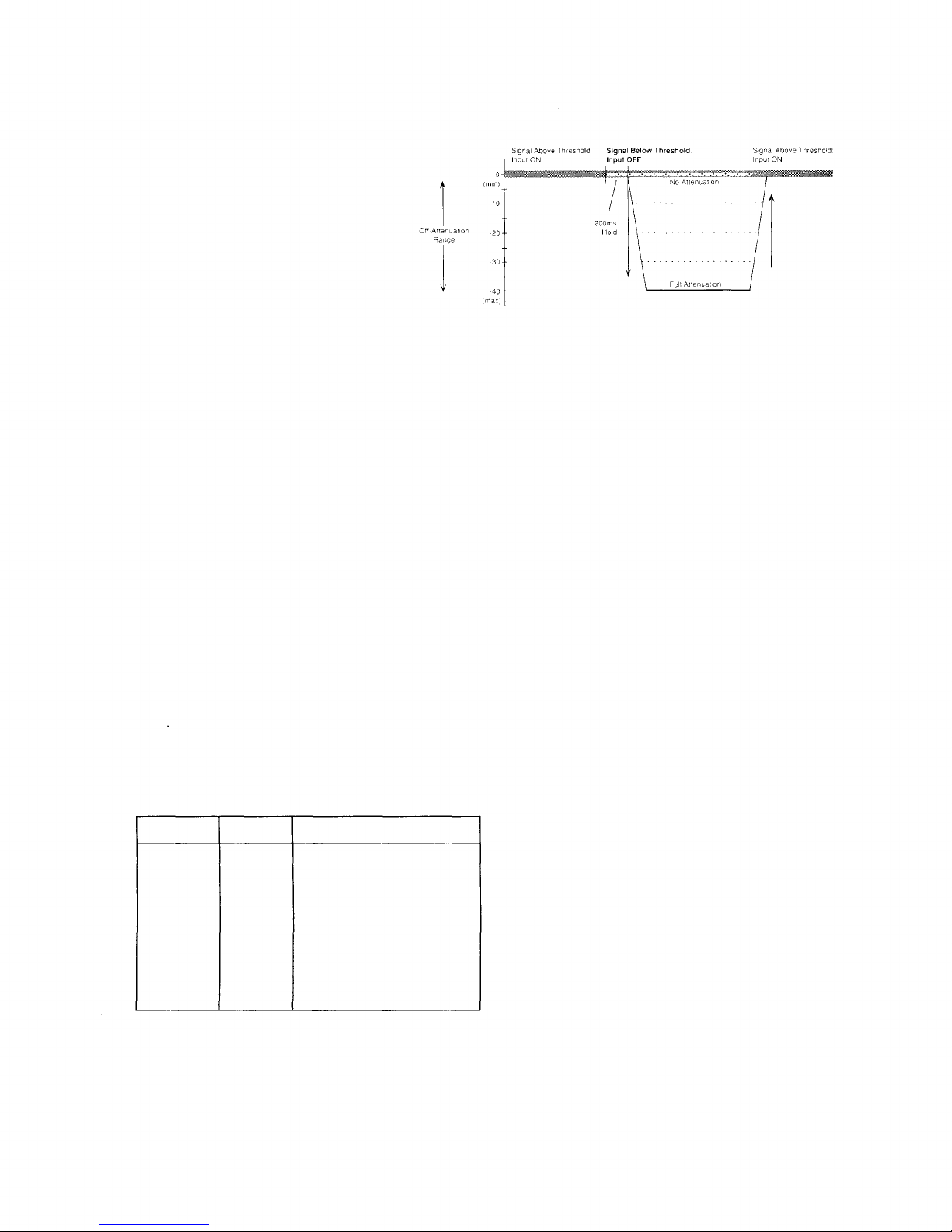
Adaptive Threshold circuit
Variable NOM Attenuation-
Output Gain from log NOM to
2 log NOM
Individual channel Threshold
and Off-Attenuation adjustment
Automatic or manual mixing is
user-configured
Internal Mute on any selected
combination of inputs
Input External Mute on any
mutable modules
Direct Outputs
Logic Outputs
Master Remote Volume Control
terminal
transformer-
isolated, balanced output.
INTRODUCTION
The AX-1 A is an economical and very versatile mixer. This manual will help you understand how to include the
AX-1 A in highly engineered sound systems. If you are simply installing a single AX-1 A for microphone
mixing (with perhaps a line input for music), the procedure is very simple. Basics are covered in Section 3~9:
3. Installation
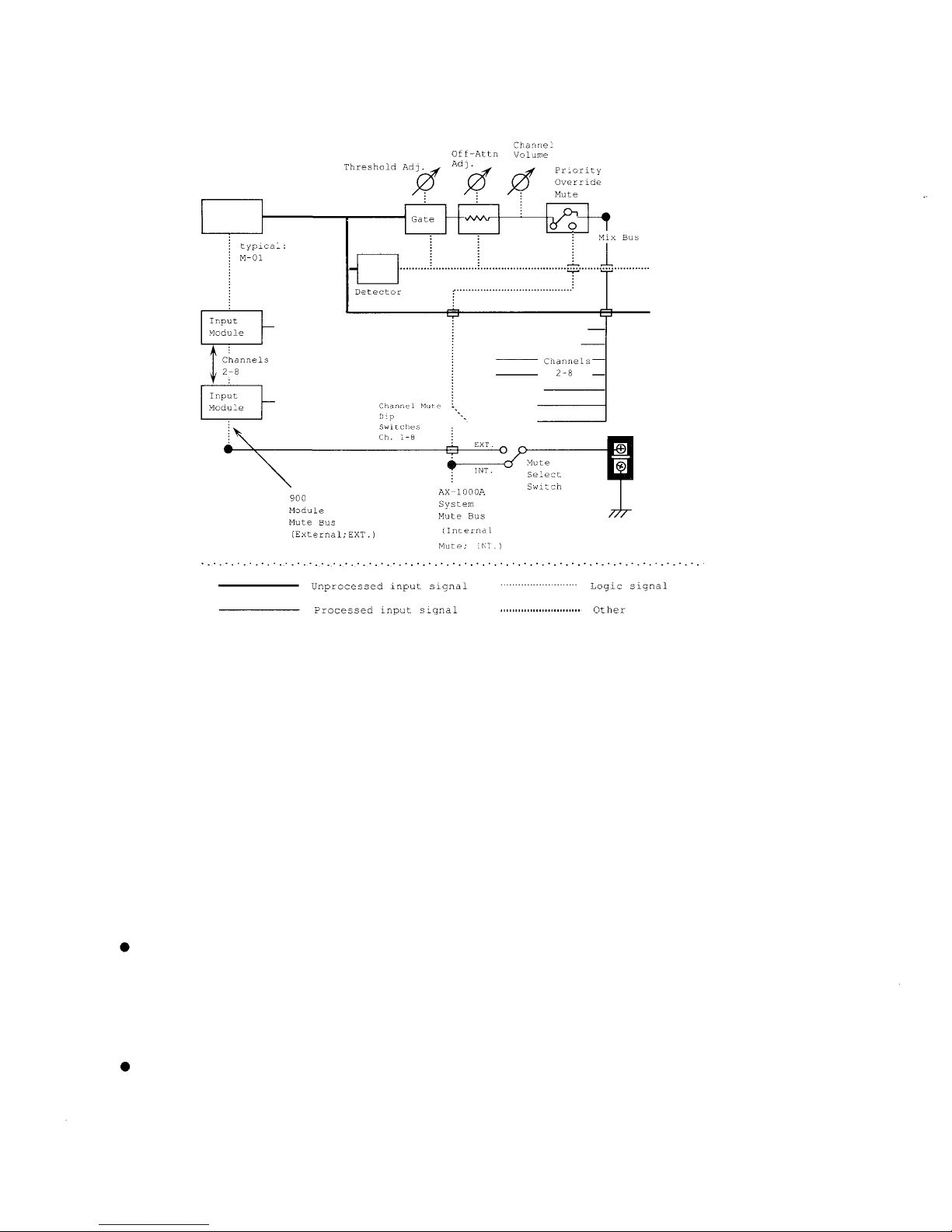
4. Input Signal Flow
5. Input Connections
6. AX-1 A Configuration: Quick Setup
7. Output Connections
8. Operation: Setup Checklist
9. Setting Up Input Modules
You will also find TOA's Input Module Instruction Manual helpful. Most of the time, this is all you need to know to
specify and install the AX-1 A. An Installation and Setup Checklist has been included in the Appendix. Copy the
pages for a complete on-the-job reminder of setup operations.
Because of its rich feature set, an AX-1 A can be used in almost any commercial application. However, if you
progress beyond basic applications it is a requirement that you study this manual carefully. Using the AX-1 A's
controls in Advanced Applications is covered in Sections 7-11.
3
EATURES
NOM Attenuation
The AX-1 A's NOM Attenuation circuitry automatically adjusts gain level according to the number of active
inputs. NOM = Number of Open Microphones. Most automatic mixers reduce output according to the formula 1
log NOM. When two mic inputs are active, the system gain is lowered 3 dB; when four are active, the output is
reduced by 6 dB; etc. TOA's NOM Attenuation circuitry allows adjustment from to 2 log NOM depending on the
system specifications. Consequently, installations incorporating the AX-1 A deliver maximum acoustic gain
without feed back.
900 Series Compatibility
Each of the AX-1 A's eight input ports accepts 9 Series Mic Level, Auxiliary, Phono, 6 ohm and 1 k ohm
Bridging, Signal Generator Modules and the T- 2 Module for Music-on-Hold. This allows the contractor or
specifying engineer ultimate flexibility in system design.
Up to ten AX-1 A mixers may be linked together to create a system with a maximum of 8 active input
channels. When units are linked, one mixer in the chain is the Master. This is accomplished by setting the
rear-panel Master/Slave switches.
In addition to the Main Output, the AX-1 A provides Direct and Logic Outputs for each channel.
Channel Direct Outputs
Channel Direct Output uses are limited only by the application. For example, direct signals can be input to a
logging recorder to provide an account of courtroom proceedings while the mixer controls the communications
system itself. Or, the Direct Outputs from certain channels can be fed into a second mixer or mixer-amplifier.
Logic Outputs
The Logic Output is an isolated open collector circuit that will trigger external devices. Applications include video
camera control, tape recorder control, and control of distributed speaker systems.
Input Channel Controls
Each channel has an Input Volume Control.
This adjusts channel gain and allows balancing
the mixing among the eight audio sources.
Behind a front-panel security cover lie the trim
controls for each channel's Threshold and
Off-Attenuation. The Threshold control adjusts
the signal level at which the input switches from
'off' to 'on'. As automatic mixing occurs, the
AX-1 A uses this setting as the 'base line'
and changes each channel's Threshold in an
adaptive manner.
Off-Attenuation sets channel attenuation depth
when the gate is 'off'. Inactive inputs may be
attenuated from dB to as much as 4 dB.
4
Variable Off-Attenuation
Adjustable Off-Attenuation allows the fine
adjustment necessary to assure smooth
channel turn on without missed syllables. When
Off-Attenuation is dB, the mixer channel
functions as a normal mixer: there is no
attenuation of an inactive channel.
Variable Off-Attenuation
Note : When Off-Attenuation is set to 0 dB, the AX-1000A still utilizes the channel's active/inactive status
for its automatic mixing logic.
To change the automatic mixing function, use the NOM Attenuation control.
Example : Here's an unusual example that shows how flexible the AX-1 A can be. Imagine a game show
produced by a small organization with its own video studio where a single mixer must work in a wide
variety of situations.
Perhaps this game show is staged as part of employee training.
An AX-1 A can be configured as four channels of normal mixing (sound effects source, studio
paging mic with press-to-talk switch, BG/FG music cassette, and MC's lavalier mic) with four channels
of automatic mixing (four panelists or game contestants). The only requirement is to set the
Off-Attenuation appropriately.
In this example, the module complement would be :
Input
MC*
Paging
Sound FX
BGM/FGM
Person 1
Person 2
Person 3
Person 4
Module
Mic
Mic
Aux
Aux
Mic
Mic
Mic
Mic
Off-Attenuation
dB... channel always on
because mic is PTT.
dB... channel always on
4 dB... automatic
4 dB... automatic
4 dB... automatic
4 dB... automatic
* Threshold could be reset to moderately high level to
gate out rustling clothes.
5
Attenuation
in dB
Active Inputs (NOM)
One
AX-1 A
Multiple
AX-1 A's
2 logNOM
Variable
Attenuation
1 logNOM
(normal)
Variable
Attenuation
dB Attn
Inputs
Inputs
NOM Attenuation Control
The NOM Attenuation Control is variable between log NOM and 2 log NOM. This allows the AX-1 A to be
adjusted for virtually any multi-microphone application.
Often, each microphone in an acoustic space exhibits a particular feedback mode, different from the other
microphones. In these cases, 1 log NOM reduces the gain too much when more microphones become active;
thus operating the system with lower gain than optimum. In such situations, a setting between and 1 logNOM
delivers less attenuation with each doubling of active inputs, therefore eliminating unnecessary attenuation.
Feedback modes in very reverberant spaces can be additive to degree that greater attenuation than normal is
needed with more mics on. A setting between 1 log NOM and 2 log NOM provides more gain reduction than
normal as additional microphones become active, preventing feedback.
Note: NOM Attenuation affects overall system gain and is totally independent from the input attenuation
depth function.
Other eatures
The AX-1 A's Priority Override Mute is especially attractive in conference systems where the chairman must
override other delegates. Selection of which channels mute when the Mute Terminals are shorted is preset with a
DIP switch. Mute Terminal can be alternatively routed to the module mute bus.
A Master Remote Volume Control may be wired to the Remote Master Volume Terminals on the rear-panel to
enable control of the system's overall output from a podium, projection booth, or similar location. The
Off-Attenuation, Threshold and NOM Attenuation Controls are hidden by a security cover to prevent unauthorized
or unnecessary adjustments.
The AX-1 A includes the hardware necessary for mounting in standard 19" equipment cabinets.
6
1. ront View
1. Input Volume Control
Adjusts input gain, after any gain stage(s) in the chosen 9 Series module.
2. Gate On/Off Indicator
Illuminates when the channel gates on.
3. Master/Slave Indicator
Illuminates when unit is the Master in a combinable system. Master/Slave switch is on the rear-panel.
4. Threshold Control
Adjusts the channel gate-on sensitivity. Turning fully counter-clockwise lowers the threshold, resulting in
maximum sensitivity.
5. Off-Attenuation Adjustment
Adjusts the inactive-input attenuation depth.
6. NOM Attenuation Control
Adjusts the operation of the automatic mixing system's gain-sharing circuitry. ( log NOM is fully counter-
clockwise position; 2 log NOM is fully clockwise position.)
7. Master Volume Control
Adjusts the overall sound system level.
8. Power On/Off Switch and Indicator
LED illuminates when unit is turned on.
7
2. Rear View
1. Remote Master Volume Control Terminals
Use a 1 k ohm linear potentiometer (1 k ohms = no gain reduction; ohm = full gain reduction).
2. Direct Outputs
Individual outputs for each of the eight inputs. The signal originates at the output of the module plugged into the
port; it is not gated by the mixer.
3. Logic Outputs
To trigger external devices.
4. System Mute Terminals
5. Link In
When more than one AX-1 A is being utilized, slaves are daisy-chained using Link In/Out.
6. Link Out
7. Main Output Terminals
15 /6 ohm barrier strip outputs.
8. Channel Mute DIP Switches
Chooses which channels mute in response to a short across the System Mute Terminals. As shipped the
default is 'on' (channels respond to a short across the mute terminals).
9. Mute unction Select Switch
Muting may be set for Internal Mute; INT., or for External Mute; EXT. For further details see "Using the
AX-1 A System Mute Bus".
10. Master/Slave Selector
If multiple units are incorporated in a combinable system, one AX-1 A must be the Master. The additional
units must be set up as Slaves.
11. Module Input Ports
For up to eight inputs. Each active input requires a 9 Series Module. See TOA's Input Module Instruction
Manual.
12. AC use
Replace only with a fuse of the same rating. Caution: If the fuse blows, please contact TOA dealer.
8
3. Installation
Unpacking and Inspection
Upon receiving the AX-1 A, please inspect it for any shipping damage. If damage is found, notify the carrier
immediately.
Rack Mounting
The AX-1 A requires 3-unit size. Mounting
brackets are provided. Remove the four
screws securing the case at the left and right
front. Attach the rack mounting brackets. Be
certain to only use the screws that are
included on the AX-1 A unit.
Note: Allow adequate ventilation: do not block the vents in the cover. Do not locate the AX-1000A :
In unventilated areas.
In an area subject to heavy vibration.
In an area with a high ambient temperature,
or immediately adjacent to equipment which
generates large amounts of heat.
Where it is exposed to direct sunlight.
In a dusty or extremely humid area.
Caution : There are no user-serviceable parts inside. Never remove the cover, or you run the risk of a fatal
electric shock.
4. Input Signal low
Since the AX-1 A has eight input ports for 9 Series plug-in modules, it is completely flexible. Requirements
often vary from installation to installation, and the AX-1 A can be configured exactly to suit each one. In order to
change a given channel's function, simply specify the proper 9 Series input module. The signal flow from the
output of the module(s) is the same for every channel. See Figure 1.
This simplified 'map' of the signal flow does not represent the actual circuitry, only the stages of processing
that occur. Functions that occur after the signals reach the Mixing Bus have been omitted for clarity.
External/Internal Mute buses :
The AX-1 A has two Mute buses, External Mute Bus and the AX-1000A Internal Mute Bus. Each one
can operate independently, and each one operates at a different stage of the signal chain. Configuring
mutes is explained in detail, below.
9
Channel Signal low (simplified)
Logic Output
Direct Output
Mute
Terminals
Input
Ch. 1
Threshold Adjustment
The heart of an automatic mixer is the circuit that determines which inputs should gate on and which inputs should
remain off. The AX-1 A does this by comparing constantly and rapidly an individual channel's level and the
levels of all the inputs. This adaptive threshold system results in very smooth mixing.
Channel threshold determines how easily an input gates 'on'. Once the channel is 'on', the gating circuit
incorporates a preset Hold, 2 msec long, to keep the mic channel open between words as an individual speaks.
Channel threshold settings will vary from installation to installation since they depend on the acoustics of the site. If
Threshold is set too low (too sensitive), ambient noise may cause a channel's gate to flutter open and closed
randomly. If it is too high, the input will not gate open reliably when presented with a low-level signal. However,
these represent extremes. The AX-1 A's mixing circuitry works well over a range of 'middle ground' threshold
settings.
If the Threshold control is turned fully counter-clockwise, the channel remains on all the time.
Off-Attenuation
When a channel gates 'off', the output of the channel is attenuated. The factory setting is maximum attenuation, 4
dB. This is considered 'completely inaudible' for all practical purposes.
There may be applications in which an absence of ambient noise in the mix would be objectionable, or
where switching to full-attenuation would sound overly disruptive. Therefore, the Off-Attenuation may be set
at a lower level, such as 1 to 15 dB.
You may have other applications where less-than-full channel attenuation is desirable.
10