Front Panel
Peak Indicator (PEAK)
The peak indicator lights when
the pre or post EQ signal level
reaches 3dB below clipping,
giving a visual reference for
opti u setting of the tri
control.
Foldback Control (FB)
The Foldback control deter ines
the level of signal assigned to the
foldback ixing buss, thus set-
ting the level of that channel in
the on-stage onitor ix.
High Equalizer Control
(HIGH EQ)
The high EQ control alters the
high frequency response of the
input channel, providing ±13dB
at 10kHz, and ±15dB at 20kHz of
continuously variable active
shelving equalization. The "0"
detented position provides flat
audio response.
Middle Equalizer Control
(MID
EQ)
The id EQ control provides
±15dB of continuously variable
active peaking equalization at
2kHz. and has a flat audio
response when set to the "0"
detented position.
Low Equalizer Control
(LOW
EQ)
The low EQ control provides
±13dB at 100Hz and ±15dB at
50Hz of continuously variable
active shelving equalization.
The "0" detented position pro-
vides flat audio response.
Echo/Effects Control
(ECHO/EFF)
This control deter ines the
level of signal assigned to the
echo effects buss. Rotating the
control clockwise increases the
a ount of echo effect in that
channel.
Input Level Control
(INPUT LEVEL)
The level control provides con-
tinuously variable adjust ent
of the channel output of the
progra ixing buss, thus deter-
ining the level of that channel
in the ain sound syste ix.
Since the echo/effects signal is
"post" this control, an increase
in the level of the channel's
output will also result in a cor-
responding increase in the echo
effect of that channel. The
no inal level of the input level
control is at the "10" position.
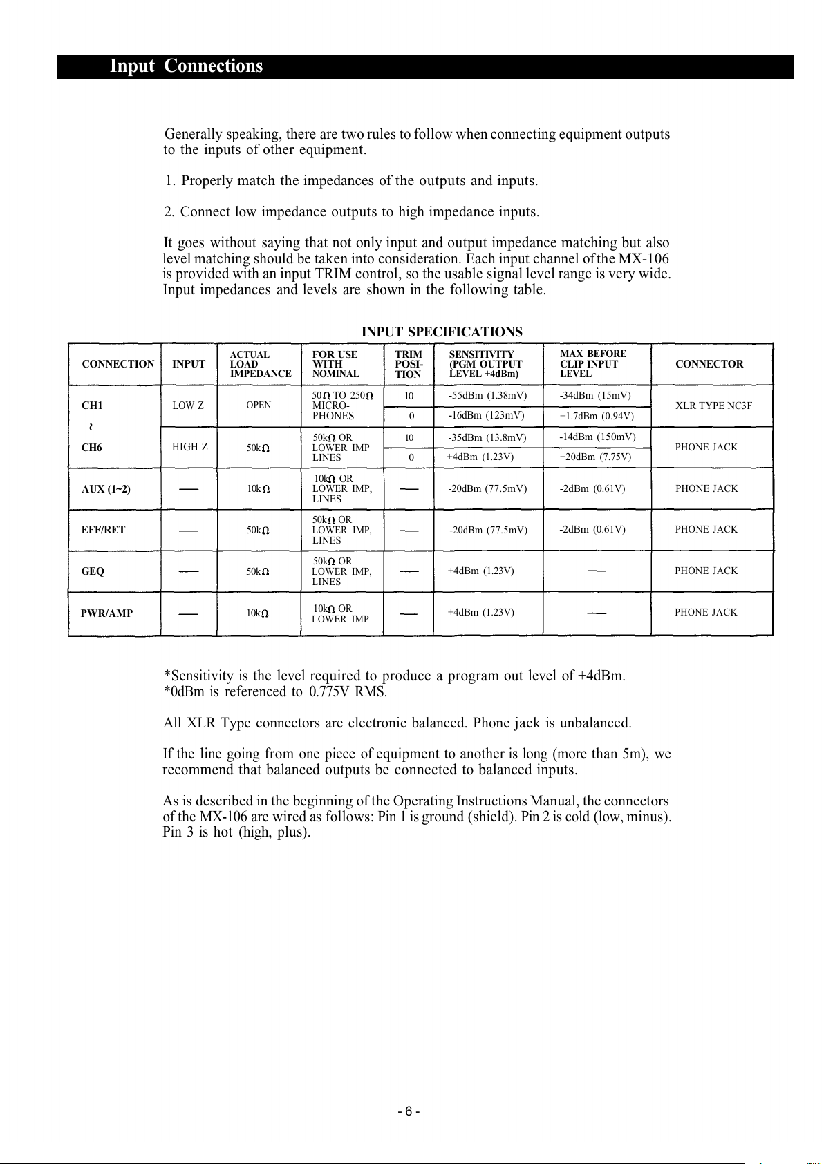
Input Tri Control (TRIM)
The input tri adjusts the gain
of the head-a p stage of the
associated channel, providing
39dB of gain control. When the
tri control is set to the "10"
position, the no inal input
levels of the low-Z and high-Z
inputs are —55dB and —35dB
respectively. At the "0" position
the levels are -16dB and +4dB.
The tri of each channel should
be adjusted so that the peak LED
just begins to light, or only
flashes occasionally. This will
ensure lowest distortion levels
and opti u signal to noise
ratio.
Foldback Master Control (FB)
The FB aster control adjusts
the overall co bined signal
level of the six independent
channel foldback sends, and
thus the level of the entire on-
stage onitor ix.
Echo/Effects to Foldback
Control (ECHO/EFF TO FB)
This control adjusts the a ount
of echo/effects signal that is
returned to the foldback buss
and thus the level of echo/effects
contained in the on-stage oni-
tor
ix.
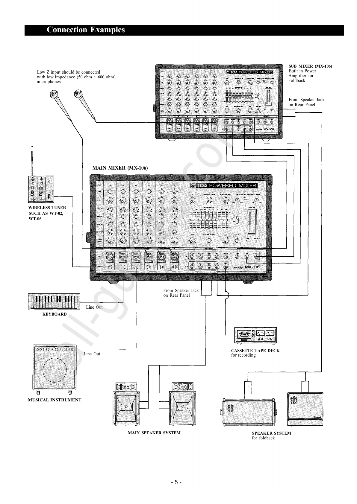
Low I pedance Connectors
(LOW
Z)
The XLR connectors are low
i pedance, electronically bal-
anced inputs with an input
i pedance of 1k oh s.
High I pedance Connectors
(HIGH Z)
These connectors are unba-
lanced, standard 1/4" phone
jacks with an input i pedance
of 50k oh s, and an input level
of —35dB when the tri control
is set t o "10". When a plug is
inserted into the high —Z input,
the corresponding XLR connec-
tor is auto atically switched
out of the input circuitry.
Progra Master Control
(PGM)
The PGM control adjusts the
overall co bined signal level of
the six independent channel
level controls, and thus the level
of the ain sound syste .
Echo/Effects to Progra
Control (ECHO/EFF TO PGM)
This control adjusts the a ount
of echo/effects signal that is
returned to the progra buss
and thus the level of echo/effects
contained in the ain sound
syste .
Aux Level Control (AUX)
This control sets the overall
level of the Aux input signal.
Patching Jack
(PATCH BAY/IN)
Patching Jack
(PATCH BAY/OUT)
Aux Panpot (AUX PAN)
This control assigns the auxili-
ary input signal (a tapedeck,
etc., connected to the aux input
jacks) to either the progra or
the foldback ixing busses. At
the center position, the signal is
routed equally to both busses.
Panning fro one side to the
other gradually assigns the sig-
nal to either independently.
Power A p Co pression
Indicator (COMP)
The Co p LED lights when the
internal co pressor is acti-
vated. The co pressor is
provided to protect speaker
syste s by co pressing the
input signal level of the power
a plifier when clipping occurs
in the output stage. Frequent
flashing of the LED is not reason
for alar . However, a constant
or steady light indicates that the
MX-106 is being overdriven and
that the internal power a plifier
is possibily "under powered" for
that application. The output
level of the MX-106 should be
decreased until the LED only
flashes inter ittently.
Echo/Effects Send Control
(ECHO/EFF SEND)
This control adjusts the overall
signal level of the effects ix
that is delivered to the internal
echo unit, or to an external
effects device through the ef-
fects output. The send control
works in conjunction with the
Echo/EFF to PGM and the
Echo/EFF to FB controls to set
the overall level of echo/effects
in the ain and onitor sound
syste s.
Delay Ti e Control
(T1 DELAY)
The Tl control per its continu-
ously variable adjust ent of the
echo ti e, fro 10 seconds
(SHORT) to 100 seconds
(LONG).
Regeneration Control
(T2 REGEN)
The T2 control deter ines the
nu ber of "repeats" of the
delayed signal fro the internal
echo unit.
Graphic Equalizer
(EQUALIZATION)
The graphic equalizer is 1/1
octave with 9 independent ac-
tive bands (filters), providing
12dB of boost or cut at each
center frequency. The "0" de-
tented position provides flat
audio response.
Graphic Equalizer In/Out
Switch (IN/OUT)
The in/out switch enables co -
parison between a flat response
(out) and the equalized response
(in). The "out" position co -
pletely re oves the equalizer
fro the MX-106 circuitry.
Fluorescent Bargraph Peak
Meters (PGM/FB)
The high intensity eters enable
visual onitoring of the pro-
gra and foldback output signal
levels.
Power A p Protection
Indicator (PROTECT)
The indicator LED lights if the
power a plifier output is short-
ed, if the te perature of the unit
rises above acceptable levels, or
if DC is drifted to the speaker
outputs. If the LED should light,
speaker wiring and a bient
te perature of the MX-106
should be checked. If the LED
re ains lighted, the unit should
be referred to qualified service
personnel for repair.
Note:
The MX-106 protection circuitry
will (1) detect 'faulty conditions'
within the power a plifier, (2)
give a visual indication, and (3)
auto atically shut down until
the fault condition is alleviated.
This special circuitry ensures
axi u reliability and virtu-
ally eli inates equip ent da -
age due to unsafe or fault
conditions. Please refer to fault
protection table on page 7 for
full explanation of this i por-
tant feature.
- 3 -
Buss Link Jack
(BUSS LINK)