Cross Phase key (X PHASE)
When this key is pressed, the
LED lights and the phase of the
delayed signals of 1(L) and 3(R)
is reversed. The reversed phase
of 1(L) signal is sent to 3(R) and
mixed, with that of 3(R) sent to
1(L).
Note
Pressing the cross phase key
when the delay time of both 1(L)
and 3(R) is the same causes the
signals to cancel each other, and
as a result, no output is pro-
vided from 1(L) and 3(R). Press-
ing the key when only one (1)
MIX output jack is used, or if
the connected equipment is in-
ternally wired in parallel (even
when both L and R jacks are
used) will also result in no out-
put.
Delay time programming key
Pressing this key reduces the de-
lay time. Pressing the key con-
tinuously increases the rate of
change.
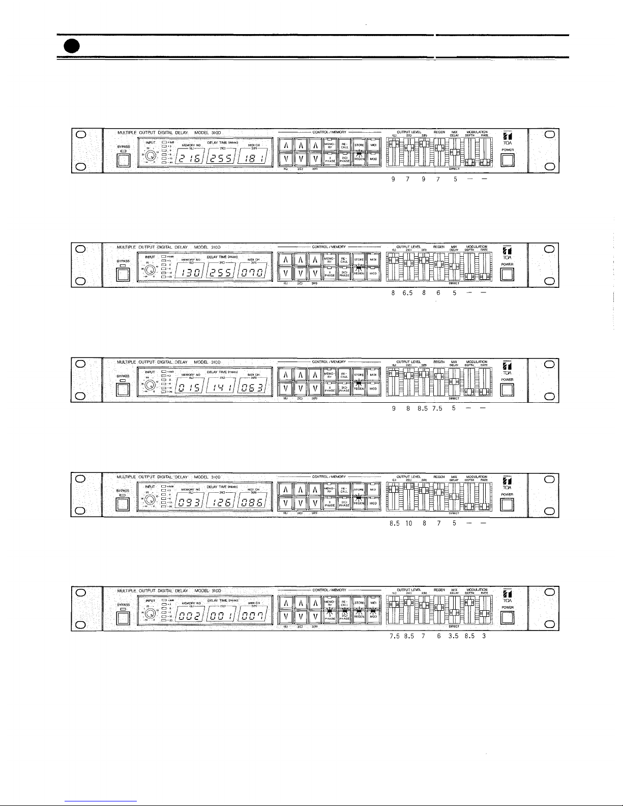
Memory Key (MEMORY)
When this key is pressed, the
LED illuminates and the mem-
ory number is indicated on the
delay time display. In order to
obtain a specific memory loca-
tion, press the or key until
the desired memory number is
displayed and then press the re-
call key.
In order to store delay times in a
specific memory number, press
the or key to select a spe-
cific memory number, and then
press the store key continuously
for 2 seconds. The memory key
LED flashes to indicate comple-
tion of storage.
The current program can be re-
tained even when power has
been switched off. The last delay
time and switch positions before
power is switched off are stored
and will be recalled automatical-
ly when the unit is again pow-
ered.
Note
The 310D is employing lithium
batteries for memory backup
purposes. Although the battery
life is longer than 5 years, the
first set of batteries may have to
be replaced earlier. Be sure to
consult qualified personnel
when replacing batteries.
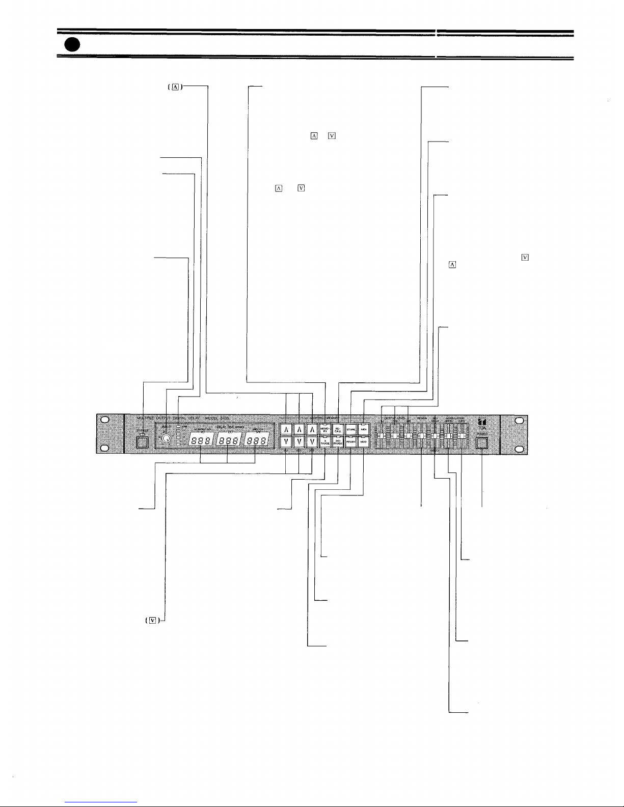
Front Panel
Delay time programming key
Pressing this key increases the
programmed delay time in mil-
liseconds. Pressing the key con-
tinuously increases the rate of
change.
Input level indicator LED's
Input level control (INPUT)
This control sets the input signal
level. To use, press and release
the control to make it spring out.
Adjust the level so the " + 6dB"
indicator LED lights intermit-
tently. (The input signal begins
to clip at +12dB.)
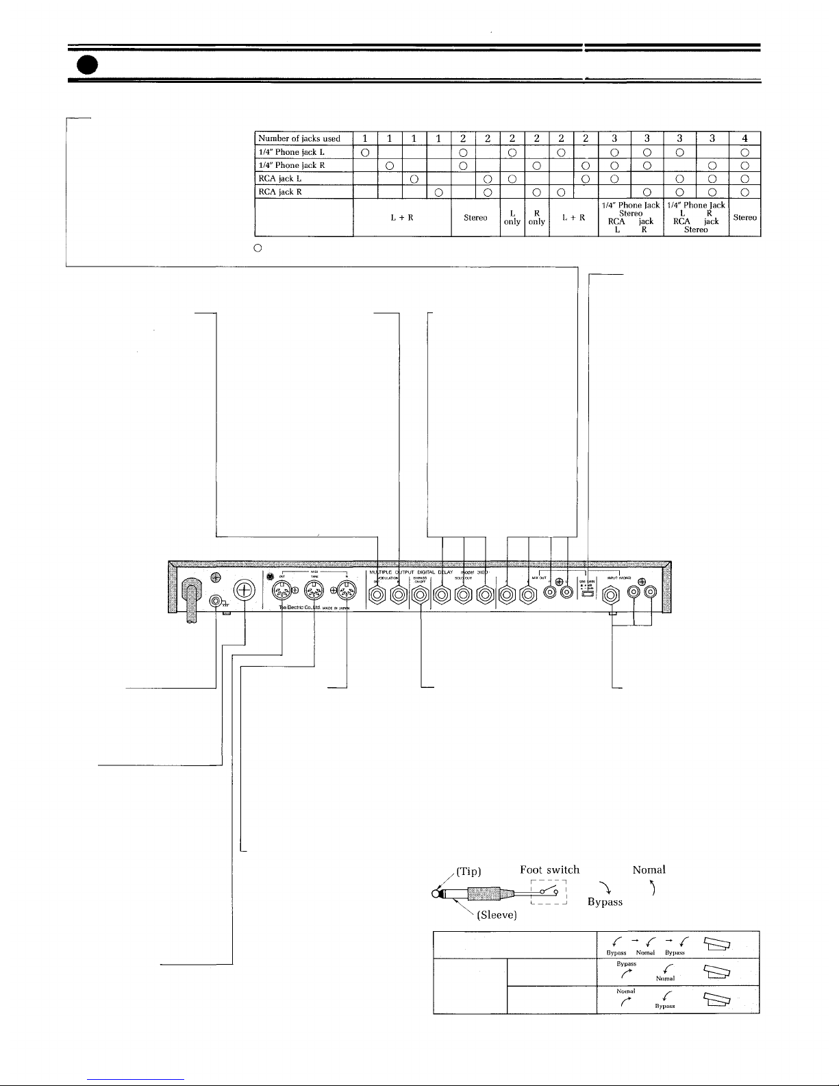
Bypass switch (BYPASS)
When this switch is pressed, the
LED comes on and the input sig-
nal is sent directly to the MIX
output terminals, bypassing the
internal circuit. If power is
switched off, the input signal
similarly bypasses the internal
circuit and goes to the MIX out-
puts directly. (In either case, the
input signal is not delivered to
Recall Key (RECALL)
Pressing this key recalls the
program stored in the specific
memory number that is selected
with the memory key.
Store Key (STORE)
Stores three different delay
times in a selected memory
number, or changes MIDI chan-
nel number.
MIDI Key (MIDI)
When this key is pressed, the
associated LED illuminates and
the MIDI channel number is in-
dicated on the delay time dis-
play.
In order to change the MIDI
channel number, press key or
key to select the desired MIDI
channel number, and then press
the store key continuously for 2
seconds, the MIDI key LED will
flash to indicate completion of
changing.
MIX output level control
(OUTPUT LEVEL)
This control adjusts the output
level of the delayed signals from
1 (L), 2 (C), and 3 (R) channels.
The output level from the SOLO
output is not affected by this
control.
Power switch (POWER)
The power switch alternately
turns AC power to the 310D
"on" and "off".
Modulation rate control
(MODULATION RATE)
This control adjusts the oscilla-
tion frequency of the built-in
low frequency oscillator. The
speed of variation of the delay
sound increases as the control is
moved upward.
Modulation depth control
(MODULATION DEPTH)
This control adjusts the delay
sound modulation ratio by the
built-in low frequency oscillator.
The modulation becomes deeper
as the control is moved upward.
Mixing level control
(MIX DELAY/DIRECT)
This control adjusts the output
level of the delayed signal. De-
lay signal to direct signal ration
=
1:1
when the control is lo-
cated in the center.
Regeneration (feedback) control
(REGEN)
This control sets the number of
regenerations of delay signal.
Modulation key (MOD)
The LED lights and the delay
time can be modulated when
this key is pressed.
Regeneration key (REGEN)
Pressing this key causes the LED
to light, and the delay signal is
regenerated.
Delay 2(C) phase key (2(C)
PHASE)
The LED lights and the phase of
signal of 2(C) is reversed when
this key is pressed.
Delay time display (DELAY
TIME)
Delay times from 0 to 999 msec
are available. 1(L), 2(C) and 3(R)
correspond with the following
MIX outputs, respectively.
1 (L): left
2 (C): center
3 (R): right
–3–
the SOLO output.)