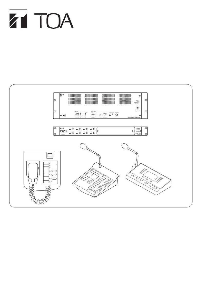
Toa VX-2000 Series Guide

Contents
2
1. General Description
.................................................................................................... 1-1
2. System Features
.......................................................................................................... 2-1
3. Maximum System Examples
3.1. Block Diagram .............................................................................................................. 3-1
3.2. Maximum System Configuration Table ......................................................................... 3-2
4. Specifications
4.1. Fireman's Microphone RM-200XF .............................................................................. 4-1
4.2. Remote Microphone RM-200X ................................................................................... 4-2
4.3. Remote Microphone Extension RM-210 ..................................................................... 4-3
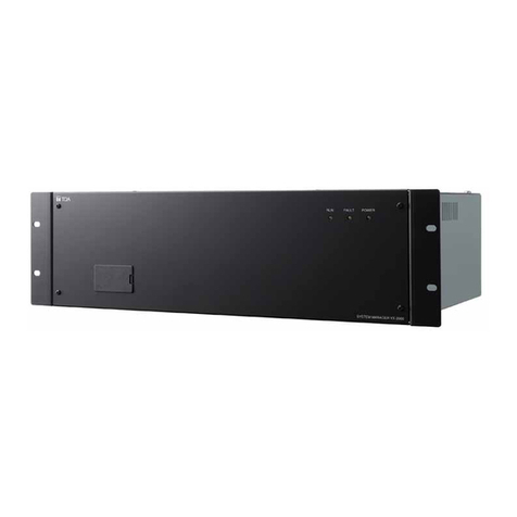
4.4. System Manager VX-2000 ......................................................................................... 4-4
4.5. Remote Microphone Input Module VX-200XR ........................................................... 4-5
4.6. Audio Input Module with Control input VX-200XI ....................................................... 4-6
4.7. Voice Announcement Board EV-200 .......................................................................... 4-7
4.8. Surveillance Frame VX-2000SF ................................................................................. 4-8
4.9. Impedance Detection Module VX-200SZ ................................................................... 4-9
4.10. Pilot Tone Detection Module VX-200SP .................................................................. 4-10
4.11. Control Input Module VX-200SI ................................................................................ 4-11
4.12. Control Output Module VX-200SO ........................................................................... 4-12
4.13. Equaliser Card VX-200SE ........................................................................................ 4-13
4.14. Power Amplifier 4 x 60 W VP-2064 ......................................................................... 4-14
4.15. Power Amplifier 2 x 120 W VP-2122 ....................................................................... 4-15
4.16. Power Amplifier 1 x 240 W VP-2241 ....................................................................... 4-16
4.17. Power Amplifier 1 x 420 W VP-2421 ....................................................................... 4-17
4.18. Power Amplifier Input Module VP-200VX ................................................................. 4-18
4.19. Power Supply Unit VX-200PS .................................................................................. 4-19
4.20. Emergency Power Supply VX-2000DS .................................................................... 4-20
4.21. Power Supply Frame VX-2000PF ............................................................................ 4-21
5. Typical System Examples
5.1. Typical System Outline
5.1.1. External View of the Building .............................................................................. 5-1
5.1.2. Internal Wiring ................................................................................................... 5-2
5.1.3. Block Diagram ................................................................................................... 5-3
5.1.4. Equipment Rack Conceptual Drawing ............................................................... 5-5
5.2. Equipment Interconnection Examples
5.2.1. VX-2000 Connections to Remote Microphones and Input Source Equipment ... 5-6
5.2.2. Connections between VX-2000 and VX-2000SF ............................................... 5-7
5.2.3. SF Modules (VX-200SP, VX-200SZ, VX-200SI, VX-200SO) Connections ........ 5-8
5.2.4. Connections Between VX-2000SF and Standby Amplifier ............................... 5-11
5.2.5. Connections Between VX-2000SF and VX-2000DS ........................................ 5-12
5.2.6. Connections Between VX-2000DS and VX-2000PS ........................................ 5-13
5.2.7. VX-2000 Cable Usage Table ............................................................................ 5-14
5.2.8. 5.2.8. VX-2000DS Cautions on Cable Connection to the Battery Terminal....... 5-17
3
Contents
5.3. Settings
5.3.1. PC Hardware Requirements ............................................................................. 5-17
5.3.2. Offline Settings ................................................................................................. 5-18
5.4. Installation
5.4.1. Online Settings ................................................................................................. 5-21
5.4.2. Connections Between VX-2000 and PC .......................................................... 5-22
5.4.3. System File Download ...................................................................................... 5-23
5.4.4. Equipment Configuration Check ....................................................................... 5-24
5.4.5. SF Initialisation and Equipment Interconnection Check ................................... 5-26
5.4.6. Introduction of Other Functions
5.4.6.1. Reading Logs
(1) Loading Logs ................................................................................. 5-29
(2) Storing Logs ................................................................................... 5-31
(3) Printing Logs .................................................................................. 5-31
5.4.6.2. Printing Out System File Settings
(1) Printing Out .................................................................................... 5-32
(2) Printout Examples .......................................................................... 5-33
5.5. System Operation
5.5.1. Emergency Mode Operation (EV Single-source Sequence) ............................ 5-53
5.5.2. Remote Microphone Operation Examples
5.5.2.1. Emergency Mode Activation and Restoration ..................................... 5-55
(1) From Emergency Mode Activation to Restoration ......................... 5-56
(2) Making a microphone restoration announcement after returning
to general-purpose broadcast mode by pressing the Emergency
Restoration key. ............................................................................. 5-58
5.5.2.2. General-Purpose Broadcast ................................................................ 5-61
(1) Making Microphone Announcements ............................................. 5-63
(2) Changing the Base Pattern ............................................................ 5-64
(3) Changing Sound Volume ............................................................... 5-65
(4) Failure Indication ............................................................................ 5-67
5.6. Examples of Connections to the VM-2120 or VM-2240
(1) Systems Using the VX-200SP Pilot Tone Detection Module ................................ 5-71
(2) Systems Using the VX-200SZ Impedance Detection Module ............................... 5-73
(3) Using the SV-200M Surveillance Board with the VM-2122 or VM-2240 ............... 5-74
6. System Examples
6.1.School
6.1.1. External View of the school ................................................................................ 6-1
6.1.2. Internal Wiring .................................................................................................... 6-2
6.1.3. Block Diagram .................................................................................................... 6-3
6.2. Department Store
6.2.1. External View of the Building .............................................................................. 6-4
6.2.2. Internal Wiring .................................................................................................... 6-5
6.2.3. Block Diagram .................................................................................................... 6-6
6.2.4. Emergency Mode Operation (Dual-Origin EV Broadcasts) ................................ 6-7

1. General Description
1-1
The TOA VX-2000 Series broadcast system is designed for both general-purpose and emergency broadcasts.
It is comprised of the System Manager, Surveillance Frame, Power Amplifiers, Power Supply unit, Emergency
Power Supply, and a user-specified number of Remote Microphones. The system complies with the EN60849
Standard and its failure detection circuitry operates continuously to check components and speaker lines for
any irregularities. If detected, failure warnings are provided by way of an LED indicator and a buzzer.

2-1
2. System Features
2. System Features
Modular System Offers Connection to Various Sound Sources.
The VX-2000 System Manager features 8 input slots that permit the use of various input sources with the
selection of corresponding modules.
Up to 8 Remote Microphones Can Be Connected.
• A total of 8 RM-200X and RM-200XF Remote Microphones can be connected to the VX-2000. Up to 4 RM-
200XF units can be installed.
• RM-210 extension capability permits the number of Remote Microphone function keys to be increased to up
to 105 keys per unit.
• The system can be configured for up to 305 function key settings.
Sound Source Devices
• Up to 2 EV-200 units can be connected to the VX-2000.
• The VX-2000 features 4 different chime sound sources.
Standard-Equipment Control Input and Output
The VX-2000 features 16 control inputs and 16 control outputs as standard equipment.
Expansion to Up to 50 Output Zones
The VX-2000SF Surveillance Frame can be expanded to up to 5 units, increasing the number of available
output zones to up to 50 zones.
Control Input and Output Modules, and 2 Types of Speaker Output Modules
• The VX-2000SF is designed to accept up to 10 modules. The control input module, control output module,
and 2 types of speaker output modules are available.
• Speaker output modules feature failure-detection circuitry. Two failure detection methods are provided:
impedance checking and pilot signal monitoring. Such failure modes as speaker line shorts, open circuits
and ground faults can be detected.
• With the addition of extra control input modules and control output modules, the number of control inputs
and outputs can be expanded to up to a total of 128 terminals within the system. (Sixteen terminals are
included as standard equipment in the VX-2000.)
9-Band Graphic Equaliser Card
Provides 9 bands of computer-adjustable graphic equalisation to the system's speaker output module.
Standby Amplifier Function
A standby amplifier can be installed for each VX-2000SF to automatically provide substitute amplifier output
should the main power amplifier fail.
CPU OFF Switch
Enables broadcast from the RM-200XF Fireman's Microphones to all output zones even if the system's main
CPU fails.

2. System Features
2. System Features
2-2
Individual Block Failure Detection Circuitry
• This failure detection function monitors cable connections between the Remote Microphones and the VX-
2000, between the VX-2000 and the VX-2000SF, between the VX-2000SF and the VP power amplifiers, and
between the VP power amplifiers and the speakers.
• The function detects and warns of such failure modes as blown fuses or overheating in the VP power
amplifier.
• Can detect and indicate failure of the VX-2000DS' charging circuitry, or battery irregularities.
Failure Indication
• The failure LED indicators for the VX-2000, VX-2000SF and Remote Microphone light when any failure is
detected within the system.
• The failure indication function can be assigned to the Remote Microphone. When assigned, the LEDs flash
and a buzzer is sounded if a failure is detected.
Monitoring Function
The sound output of a selected output zone can be monitored using the Remote Microphone's internal
speaker or the VX-2000's monitor output.
Time Schedule Function
• A weekly schedule can be programmed.
• Up to 40 specific day programs can be set for any desired date and time.
• A summertime period can be set by either the system's PC software or the VX-2000's Summertime Setting
switch.
Energy Saving Mode
Battery consumption can be reduced by using the VP power amplifier's standby function (since the entire
system's power consumption is reduced by putting unnecessary power amplifiers in standby mode).
PC Setting Software
PC software is used to select input and output equipment, or set priorities, broadcast patterns, items to be
activated, etc. Various functions can also be freely assigned to the Remote Microphone' s function keys.
PC Software Provides Versatile Auxiliary Operation
• The VX-2000's memory can log up to 2,000 events, which can be read into a PC.
• System block diagrams and individual equipment settings can be printed out using the VX-2000's PC
software.
• Remote Microphone function key names can be printed out and used as name labels.
• System configurations and connections can be checked during equipment installation.
• Inspection mode permits inspection of emergency broadcast equipment operations without actually making
broadcasts.

3-1
3. Maximum System Examples
3.1. Block Diagram
MD Player
CD Player
RM-200XF + RM-210 x 10
RM-200X + RM-210 x 9
RM-200XF + RM-210 RM-200X + RM-210
RM-200XF + RM-210 RM-200X
RM-200X + RM-210 RM-200XF
PM-660U
Control Input x 16
Control Output x 16
VX-2000SF No.2
VX-2000SF No.3
VX-2000SF No.4
VX-2000SF No.5
ZONE 1
SF-1
Standby Amplifier
x 16
x 16
x 16
x 16
VX-2000 VX-2000SF No.1
VX-200XR
VX-200XR
VX-200XR
VX-200XR
VX-200XR
VX-200XI
U-01R
EV-200 No.1
EV-200 No.2
Chime
U-01R
VX-200SZ VP-200VX
VP-200VX
VP-200VX
VP-200VX
VP-200VX
VP-200VX
VP-200VX
VP-200VX
VP-200VX
VP-200VX
VP-200VX
VP-200VX
VP-200VX
VP-200VX
VP-200VX
VP-200VX
VP-200VX
VP-200VX
VP-200VX
VP-200VX
VX-200SZ
VX-200SZ
VX-200SZ
VX-200SZ
VX-200SP
VX-200SP
VX-200SP
VX-200SP
VX-200SP
VX-200SZ
VX-200SZ
VX-200SZ
VX-200SZ
VX-200SP
VX-200SP
VX-200SP
VX-200SI
VX-200SO
VX-200SZ
ZONE 2
ZONE 3
ZONE 4
ZONE 6
ZONE 7
VP-2064
ZONE 5
VP-2122
VP-2241
ZONE 9
ZONE 8
ZONE 10
VP-2122
VP-2421
VP-2421
ZONE 42
SF-5
Standby Amplifier
ZONE 43
ZONE 44
ZONE 45
ZONE 48
VP-2064
VP-2241
ZONE 41
VP-2241
ZONE 47
ZONE 46
VP-2122
VP-2241
The following block diagram shows the maximum size system that can be assembled with the VX-2000 Series.

3. Maximum System Examples
3-2
3.2. Maximum System Configuration Table
Component
Input Source Equipment
Maximum No. of Units
RM-200XF
RM-200X
EV-200
Chime (built-in)
Paging Microphone and Music
Sources (MD, CD, etc.)
4 units
8 units
2 units
1 unit
8 units
8 units in total of
both models
18 units in total of all
Input Source Equipment
RM-200XF's and RM-200X's Function Key Extension
RM-210 10 units per RM-200XF
9 units per RM-200X
315 function keys per system
VX-2000
VX-2000 1 unit
VX-2000SF
VX-2000SF 5 units
Input Module
VX-200XR
VX-200XI
900 module
8 units in total of all Input Modules
Usable 900 modules: M-01F, M-01M, M-01P, M-51F, M-51S, M-61F, M-61S,
U-01F, U-01P, U-01R, U-01S, and U-61S
SF Module
VX-200SP 50 units
VX-200SZ 50 units
VX-200SI 7 units
VX-200SO 7 units
50 units in total of all SF Modules
(10 units per VX-2000SF)
Optional Equaliser Card (to be installed in VX-200SP and VX-200SZ)
VX-200SE 50 units
Control Input
VX-2000
VX-200SI
16 inputs
(as standard equipment)
112 inputs (7 units)
128 inputs in total
Control Output
VX-2000
VX-200SO
16 outputs
(as standard equipment)
112 outputs (7 units)
128 outputs in total
Power Amplifier
VP-2064 (4 ch)
VP-2122 (2 ch)
VP-2241 (1 ch)
VP-2421 (1 ch)
50 channels (50 zones)
Standby Amplifier 5 channels (1 channel per VX-2000SF)
Note: The number and type of power amplifiers should be determined
depending on the required speaker output for each zone.
Note: Necessary power capacity should be calculated based on total system
specifications.
Power Amplifier Input Module
VP-200VX 55 units in total of modules installed in Power and Standby Amplifiers
Power Supply
VX-2000DS 10 units 2 units per VX-2000SF
VX-200PS 30 units 2 units per VX-2000DS
Battery 40 units 2 or 4 units per VX-2000DS

4-1
4. Specifications
4.1. Fireman's Microphone RM-200XF
[Top] [Bottom][Side]
* 0 dB = 1 V
Note: LONWORKS is a trademark of Echelon Corporation.
• Accessory
Plug-in screw terminal ................................1
Wall mounting bracket ................................1
Wall mouting screw ....................................2
Box mounting screw ...................................2
(Applicable Box: YC-301, YS-11A)
24 V DC (Operating range: 16 – 40 V DC)
Under 200 mA (RM-200XF), 850 mA (with 10 RM-210s connected)
0 dB*, 600Ω, balanced
Dynamic microphone, Function switch (default: Press-to-talk),
Microphone element fault detection
Under 1%
200 – 15,000 Hz
Over 55 dB
200 mW
Microphone volume control, Monitor speaker volume control
5 (including Hand-held microphone's switch),
extendable up to 105 (with 10 RM-210s connected)
10 keys extension per RM-210, EXTENSION connector
4
LONWORKS twisted pair free topology transceiver
Category 5 STP cable, plug-in screw connector
500 m (Free topology wiring)
ABS resin, blueish gray (PANTONE 538 or its equivalent)
200 (w) x 215 (h) x 82.5 (d) mm (excluding the coiled cord)
1.2 kg
Power Source
Current Consumption
Audio Output
Hand-Held Microphone
Distortion
Frequency Response
S/N Ratio
Internal Monitor Speaker
Volume Control
Number of Function Keys
Key Extension
Number of Connectable Units
Communication System
Connection Cable and Connector
Communication Distance
Finish
Dimensions
Weight

4. Specifications
4-2
4.2. Remote Microphone RM-200X
[Top] [Side] [Rear]
* 0 dB = 1 V
Note: LONWORKS is a trademark of Echelon Corporation.
24 V DC (operating range: 16 – 40 V DC), supplied from RJ45 connector
or power input jack (non-polarity type)
Usable power input plug: 5.5 mm outer diameter, 2.1 mm inner diameter,
and 9.5 mm long
Under 200 mA (RM-200X), 750 mA (with 9 RM-210s connected)
0 dB*, 600Ω, balanced, RJ45 connector
Unidirectional electret condenser microphone
–40 dB*, 2.2kΩ, unbalanced, mini jack, phantom powering
Under 1%
100 – 20,000 Hz
Over 60 dB
200 mW
Microphone volume control, Monitor speaker volume control
15, extendable up to 105 (with 9 RM-210s connected)
10 keys extension per RM-210, EXTENSION connector
8 (include RM-200XF)
LONWORKS twisted pair free topology transceiver
Category 5 STP cable, RJ45 connector
500 m (Free topology wiring)
ABS resin, blueish gray (PANTONE 538 or its equivalent)
190 (W) x 76.5 (H) x 215 (D) mm (gooseneck microphone excluded)
850 g
Power Source
Current Consumption
Audio Output
Gooseneck Microphone
External Microphone Input
Distortion
Frequency Response
S/N Ratio
Internal Monitor Speaker
Volume Control
Number of Function Keys
Key Extension
Number of Connectable Units
Communication System
Connection Cable and Connector
Communication Distance
Finish
Dimensions
Weight

4-3
4. Specifications
4.3. Remote Microphone Extension RM-210
[Top]
[Rear]
[Side]
• Accessories
Extension cable .......................................... 1
Linkage bracket A ...................................... 2
Linkage bracket B ...................................... 1
Screw for linkage bracket ......................... 12
20mA max. (in terms of RM-200M's DC power input)
75mA max. (in terms of DC power inputs of RM-200X and RM-200XF)
Connection to RM-200M, RM-200X or RM-200XF by way of dedicated cable
10
When used to expand the RM-200M:
Selects and activates the Voice Announcement Board messages.
When used to expand the RM-200X and RM-200XF (PC software setting):
Emergency activation, emergency reset, BGM pattern selection,
EV message activation, broadcast zone selection,
monitor zone selection, chime activation, Talk switch activation,
control output activation, input volume adjustment,
zone volume adjustment, and failure output indication and reset.
ABS resin, blueish gray (PANTONE 538 or its equivalent)
110 (W) x 76.5 (H) x 215 (D)mm
350g
Current Consumption
Connection
Number of Function Keys
Function
Finish
Dimensions
Weight

4. Specifications
4-4
4.4. System Manager VX-2000
[Front section without front panel]
[Rear]
[Front]
Power Source 24V DC (operating range: 20 – 40V DC)
M3.5 screw terminal, distance between barriers: 8.8m
Current consumption Under 650mA (20V DC)
Input –20dB*, unbalanced, Number of module slots: 8
Usable module: VX-200XR, VX-200XI, 900 series plug-in modules (M-01F,
M-01M, M-01P, M-01S, M-03P, M-51F, M-51S, M-61F, M-61S, M-61T, U-01F,
U-01P, U-01R, U-01S, U-01T, M-03R, U-03S, U-61S, U-61T)
Audio Link Output Number of audio buses: 4
0dB*, electronically balanced, RJ45 female connector
Twisted-pair straight cable (TIA/EIA-568A standard)
Monitor Output 0dB*, electronically balanced, XLR receptacle (3 pins)
Frequency Response 20 – 20,000Hz
S/N Ratio Over 60dB
Distortion Under 0.5%
Cross Talk Under –60dB (1kHz, 0dB*)
Control Input 16 inputs, no-voltage make contact, open voltage: 17V DC,
Short circuit current: Under 5mA, RJ45 connector x 2
Control Output 16 outputs, open collector output, withstand voltage: 30V DC,
Control current: Under 5mA, RJ45 connector x 2
Chime Tone Built-in chime: 4-tone chime (up)/4-tone chime (down)/2-tone chime/Gong
Communication System PC (Setting software to be installed): D-sub connector (9 pins), cross cable,
RS-232C
VX-2000SF: RJ45 female connector,
Twisted-pair straight cable (TIA/EIA-568A standard), LONWORKS RS-485
Operating Temperature 0˚ C to +40˚ C
Finish Panel: Surface-treated steel plate, black, 30% gloss, paint
Dimensions 482 (W) x 132.6 (H) x 337 (D)mm
Weight 6.4kg
• Accessories
Rack mounting bracket (preinstalled on the unit) x 2, Rack mounting screw x 4, Fiber washer x 4,
Blank panel x 7, Blank panel mounting screw x 14, Setting software installation CD x 1,
Fuse (T1.6A L) x 1/(T6.3A L) x 1
* 0 dB = 1 V
• Optional products
Voice announcement board: EV-200, Isolation transformer: IT-450 (audio link output)

4-5
4. Specifications
4.5. Remote Microphone Input Module VX-200XR
Supplied from VX-2000
Under 15 mA
RM-200X and RM-200XF
RJ45 female connector
Twisted-pair straight cable (TIA/EIA-568A standard)
Panel: Alumite finished aluminum, white
35 (W) x 78 (H) x 88 (D) mm
70 g
VX-2000
Power Source
Current Consumption
Connectable Remote Microphone
Input Connector
Finish
Dimensions
Weight
Applicable Model
[Front] [Side]
• Accessory
Mounting screw .......................................... 2

4. Specifications
4-6
4.6. Audio Input Module with Control input VX-200XI
Supplied from VX-2000
Under 30 mA
MIC: –70 to – 42.5dB* (adjustable)
LINE: –20 to +7.5dB* (adjustable)
MIC or LINE selectable by the built-in switch
9 to 15 dB attenuation (adjustable)
8 to 14 dB attenuation (adjustable)
Under 0.5%
50 – 20,000 Hz
15V (open), 6V (current consumption: 3.3mA)
No-voltage make contact, open voltage: 17V DC,
short-circuit current: Under 5mA
RJ45 female connector
Twisted-pair straight cable (TIA/EIA-568A standard)
Panel: Alumite finished aluminum, white
35 (W) x 78 (H) x 88 (D) mm
70 g
VX-2000
*0 dB = 1 V
Power Source
Current Consumption
Input Sensitivity
(Rated Output –20dB)
Low Cut Filter (100 Hz)
High Cut Filter (10 kHz)
Distortion
Frequency Response
Phantom Power
Control Input
Input Connector
Finish
Dimensions
Weight
Applicable Model
[Front] [Side]
• Accessory
Mounting screw............................................2
• Optional products
Isolation transformer: IT-450

4-7
4. Specifications
4.7. Voice Announcement Board EV-200
*
1
0 dB = 1 V
*
2
Trademark of SanDisk Corporation.
Note: Use the CompactFlash card adapter on the market for recording by the EV-350R.
• Accessory
Mounting screw .......................................... 2
24 V DC, 0.2 A
5 W
0 dB*
1
20 – 20,000 Hz (44.1 kHz sampling)
20 – 14,000 Hz (32 kHz sampling)
Under 0.3% (44.1 kHz, recording method: Extremely High)
SanDisk*
2
CompactFlash*
2
card is optionally required.
Number of mountable card: 1
Single source playback
8 programs
0°C to +50°C
Under than 90% RH (must be free from dew condensation)
120 (W) x 18.6 (H) x 121 (D) mm
110 g
Power Source
Power Consumption
Output
Frequency Response
Distortion
Memory Card
Playback Mode
No. of Playback Program
Operating Temperature
Operating Humidity
Dimensions
Weight
[Front]
[Top]

4. Specifications
4-8
4.8. Surveillance Frame VX-2000SF
[Front section without front panel]
[Rear]
[Front]
Power Source 24 V DC (operating range: 20 – 40 V DC)
M3.5 screw terminal, distance between barriers: 8.8m
Current consumption Under 2 A (40 V DC)
Number of Module Slot 10, usable modules: VX-200SZ, VX-200SP, VX-200SI, VX-200SO
Frequency Response 20 – 20,000Hz
S/N Ratio Over 60dB
Distortion Under 0.5%
Cross Talk Under –60dB (1kHz, 0dB*)
Audio Link Input/Output Number of audio busses: 4
0dB*, electronically balanced, RJ45 female connector
Twisted-pair straight cable (TIA/EIA-568A standard)
Standby Amplifier Link RJ45 female connector for connecting the VP-2064, VP-2122, VP-2241, VP-2421
Power Amplifier.
Twisted-pair straight cable (TIA/EIA-586A standard)
Communication System VX-2000, VX-2000SF: RJ45 female connector x 2, LONWORKS RS-485
VX-2000DS: RJ45 female connector x 2,
Twisted-pair straight cable (TIA/EIA-586A standard)
Operating Temperature 0˚ C to +40˚ C
Finish Panel: Surface-treated steel plate, black, 30% gloss, paint
Dimensions 482 (W) x 132.6 (H) x 337 (D)mm
Weight 5.6 kg
* 0 dB = 1 V
Note: LONWORKS is a trademark of Echelon Corporation.
• Accessories
Rack mounting bracket (preinstalled on the unit) x 2, Rack mounting screw x 4, Fiber washer x 4,
Blank panel x 9, Blank panel mounting screw x 18, Standby amp. cable (3m) x 1
• Optional products
Isolation transformer: IT-450 (audio link output)

4-9
4. Specifications
4.9. Impedance Detection Module VX-200SZ
[Side][Front]
[Top]
• Optional product
Equaliser card: VX-200SE
• Accessory
Plug-in screw terminal ................................ 1
Supplied from VX-2000SF
Under 150mA
RJ45 female connector for connecting the VP-2064, VP-2122,
VP-2241, VP-2421 Power Amplifier.
Twisted-pair straight cable (TIA/EIA-568A standard)
Plug-in screw connector, relay, no-voltage make contact output, transfer type,
withstand voltage: 30V DC, 250V AC, contact current: Under 7A (DC),
under 7A (AC)
Applicable cable diameter: AWG24 – AWG 22
Plug-in screw connector
Applicable cable diameter: AWG24 – AWG 22
Plug-in screw connector for connecting the VP-2064, VP-2122, VP-2241,
VP-2421 Power Amplifier.
Applicable cable diameter: AWG24 – AWG 22
Short circuit, open circuit (impedance detection method), ground fault
Panel: Surface-treated steel plate
30.5 (W) x 132.6 (H) x 290.3 (D)mm
320g
VX-2000SF
Power Source
Current Consumption
Power Amplifier Link
External Attenuator Control
Output
Speaker Output
Power Amplifier Input
Fault Detection System
Finish
Dimensions
Weight
Applicable Model

4. Specifications
4-10
4.10 Pilot Tone Detection Module VX-200SP
[Side]
[Front]
[Top]
• Optional product
Equaliser card: VX-200SE
• Accessory
Plug-in screw terminal ................................ 1
Supplied from VX-2000SF
Under 100mA
RJ45 female connector for connecting the VP-2064, VP-2122, VP-2241,
VP-2421 Power Amplifier.
Twisted-pair straight cable (TIA/EIA-568A standard)
Plug-in screw connector
Applicable cable diameter: AWG24 – AWG 22
Plug-in screw connector, relay, no-voltage make contact output, transfer type,
withstand voltage: 30V DC, 250V AC, contact current: Under 7A (DC),
under 7A (AC)
Applicable cable diameter: AWG24 – AWG 22
Plug-in screw connector
Applicable cable diameter: AWG24 – AWG 22
Plug-in screw connector for connecting the VP-2064, VP-2122,
VP-2241, VP-2421 Power Amplifier.
Applicable cable diameter: AWG24 – AWG 22
Short circuit, open circuit (pilot tone detection method), ground fault
Panel: Surface-treated steel plate
30.5 (W) x 132.6 (H) x 290.3 (D)mm
240g
VX-2000SF
Power Source
Current Consumption
Power Amplifier Link
Line Monitor
External Attenuator Control
Output
Speaker Output
Power Amplifier Input
Fault Detection System
Finish
Dimensions
Weight
Applicable Model

4-11
4. Specifications
4.11. Control Input Module VX-200SI
[Side][Front]
[Top]
Supplied from VX-2000SF
Under 100 mA
16 inputs, no-voltage make contact, open voltage: 24V DC,
short circuit current: under 10mA, RJ45 connector
Panel: Surface-treated steel plate
30.5 (W) x 132.6 (H) x 290.3 (D) mm
200 g
VX-2000SF
Power Source
Current Consumption
Control Input
Finish
Dimensions
Weight
Applicable Model

4. Specifications
4-12
4.12. Control Output Module VX-200SO
[Side][Front]
[Top]
Supplied from VX-2000SF
Under 150 mA
16 outputs, no-voltage make contact, contact capacity: 28V DC, 1A,
RJ45 connector
Panel: Surface-treated steel plate
30.5 (W) x 132.6 (H) x 290.3 (D) mm
250 g
VX-2000SF
Power Source
Current Consumption
Control Output
Finish
Dimensions
Weight
Applicable Model
Other manuals for VX-2000 Series
1
This manual suits for next models
2
Table of contents
Other Toa Security System manuals

Toa
Toa VX-3000 SERIES User manual

Toa
Toa VX-3000IM-EB User manual

Toa
Toa VM-3000 Series User manual

Toa
Toa VS-900 User manual

Toa
Toa VX-2000 Series User manual

Toa
Toa VX-3000 SERIES User manual

Toa
Toa SX-2000AI User manual

Toa
Toa Netcansee N-VR2010 User manual

Toa
Toa ALARM INPUT UNIT C-AL80(H) User manual

Toa
Toa VX-3308WM User manual