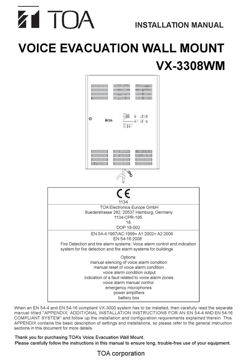
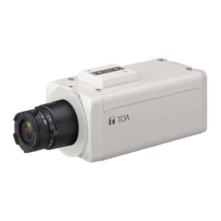
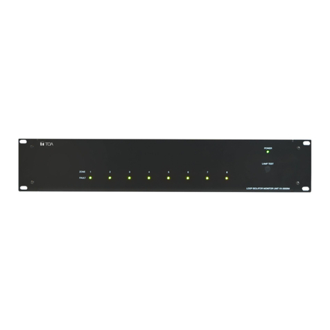
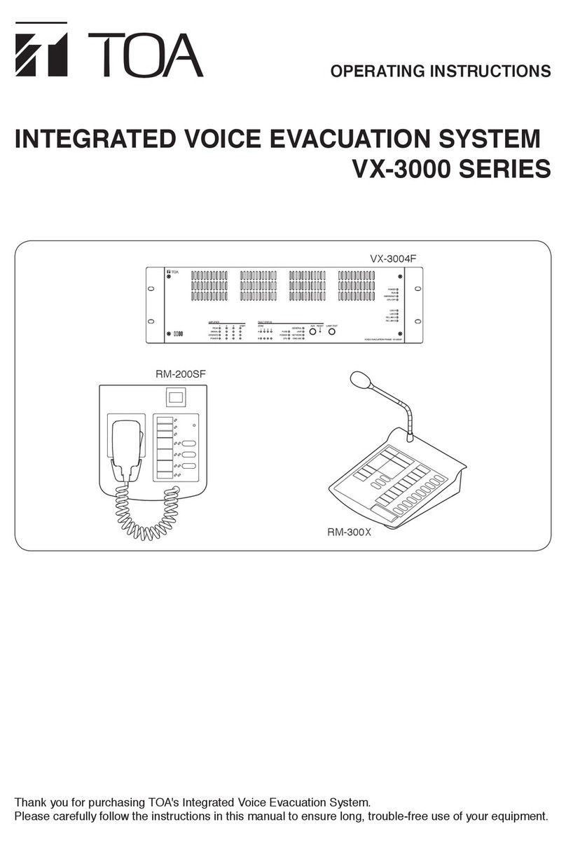
Toa VX-2000 Series User manual

INSTRUCTION MANUAL
INTEGRATED VOICE EVACUATION SYSTEM
VX-2000 series
1134
TOA Electronics Europe GmbH
Suederstrasse 282, 20537 Hamburg, Germany
1134-CPR-110
EN 54-16: 2008
Fire detection and fire alarm systems
— Part 16: Voice alarm control and indicating equipment
Options:
Audible warning of emergency
Manual silencing of the voice alarm condition
Manual reset of the voice alarm condition
Voice alarm condition output to CIE
Indication of faults related to voice alarm zones
Emergency microphone(s)
Voice alarm manual control
Redundant power amplifiers
14
DoP 14-002
Thank you for purchasing TOA's Integrated Voice Evacuation System.
Please carefully follow the instructions in this manual to ensure long, trouble-free use of your equipment.
When an EN 54-16 compliant VX-2000 system has to be installed, then carefully read the separate manual
titled "APPENDIX: ADDITIONAL INSTALLATION INSTRUCTIONS FOR AN EN 54-16 COMPLIANT
SYSTEM" and follow up the installation and configuration requirements explained therein. This APPENDIX
contains the basic description of settings and installations, so please refer to the general instruction
sections in this document for more details.
Note
Refer to the Instruction Manual attached to the VX-2000DS/3000DS for the installation of the the VX-
2000DS or VX-3000DS Emergency power supply, the VX-2000PF Power supply frame, and the VX-200PS
Power supply unit.
Система оповещения TOA VX-2000 | toa.com.ua

2
TABLE OF CONTENTS
SAFETY PRECAUTIONS ................................................................................. 10
1. GENERAL DESCRIPTION ....................................................................... 1-2
2. SYSTEM FEATURES ................................................................................... 1-3
3. HANDLING PRECAUTIONS ................................................................... 1-5
1. MAXIMUM SYSTEM EXAMPLE ........................................................... 2-2
1.1. Block Diagram .................................................................................................... 2-2
1.2. Maximum System Configuration Table ............................................................. 2-3
2. NOMENCLATURE AND FUNCTIONS ............................................. 2-4
2.1. Fireman's Microphone RM-200XF .................................................................... 2-4
2.2. Remote Microphone RM-200X ........................................................................ 2-6
2.3. Remote Microphone Extension RM-210 .......................................................... 2-8
2.4. System Manager VX-2000 ............................................................................... 2-9
2.5. Voice Announcement Board EV-200 .............................................................. 2-11
2.6. Remote Microphone Input Module VX-200XR ................................................ 2-12
2.7. Audio Input Module with Control input VX-200XI ............................................ 2-13
2.8. Surveillance Frame VX-2000SF ..................................................................... 2-14
2.9. Pilot Tone Detection Module VX-200SP ......................................................... 2-16
2.10. Impedance Detection Module VX-200SZ ...................................................... 2-17
2.11. Equaliser Card VX-200SE ............................................................................. 2-18
2.12. Control Input Module VX-200SI ..................................................................... 2-19
2.13. Control Output Module VX-200SO ................................................................ 2-20
2.14. Power Amplifiers VP-2064, VP-2122, VP-2241, and VP-2421 ....................... 2-21
2.15. Power Amplifiers VP-3154, VP-3304, and VP-3504 ....................................... 2-22
2.16. Power Amplifier Input Module VP-200VX ...................................................... 2-24
1. OPERATION MODES ................................................................................. 3-2
1.1. Drive Mode ........................................................................................................ 3-2
1.2. System Operation Mode ................................................................................... 3-2
2. MONITOR FUNCTION ............................................................................... 3-3
2.1. Continuous Monitoring ...................................................................................... 3-3
2.2. Monitoring That Requires Interval Settings ...................................................... 3-4
3. AMPLIFIER STANDBY FUNCTIONS ............................................... 3-5
4. SPEAKER LINE FAILURE DETECTION METHODS ............. 3-6
4.1. Impedance Detection Method ........................................................................... 3-6
4.2. Pilot Tone Detection Method ............................................................................. 3-6
Chapter 1: NOTE
Chapter 2: PRODUCT DESCRIPTIONS
Chapter 3: SYSTEM OPERATION OUTLINE

3
5. EXTERNAL ATTENUATOR CONTROL
TERMINAL OPERATION ........................................................................... 3-7
5.1. Operation ............................................................................................................ 3-7
5.2. Operation During Monitoring ............................................................................ 3-8
6. CPU SWITCH ................................................................................................... 3-9
7. SWITCHING OFF SYSTEM POWER ................................................ 3-10
8. BROADCAST PRIORITIES .................................................................... 3 -11
8.1. Duplicate Broadcasts from both Higher and Lower Priority Equipment ........... 3-12
8.2. FIFO/LIFO Priorities ......................................................................................... 3-13
8.3. Broadcasts from the Daisy-Chain Connected Remote Microphones .............. 3-14
1. OPERATION OUTLINE .............................................................................. 4-2
2. PATTERNS ........................................................................................................ 4-3
2.1. Emergency Broadcast Patterns ......................................................................... 4-3
2.2. Control/General-Purpose Broadcast Patterns .................................................. 4-4
2.3. Failure Output Patterns ..................................................................................... 4-5
3. ACTIVATION ITEMS .................................................................................... 4-6
3.1. Remote Microphone Function Keys .................................................................. 4-6
3.1.1. Emergency ................................................................................................ 4-7
3.1.2. Base pattern change ............................................................................... 4-8
3.1.3. Base pattern end ..................................................................................... 4-8
3.1.4. Control output interlock ........................................................................... 4-8
3.1.5. Audio monitoring ..................................................................................... 4-8
3.1.6. Volume UP operation .............................................................................. 4-9
3.1.7. Volume DOWN operation ........................................................................ 4-9
3.1.8. Failure output reception ........................................................................... 4-9
3.1.9. Failure output reset .................................................................................. 4-9
3.1.10. Zone selection ...................................................................................... 4-10
3.1.11. All-Zone selection .................................................................................. 4-10
3.1.12. Clear ..................................................................................................... 4-10
3.1.13. Talk ....................................................................................................... 4-11
3.1.14. General-Purpose EV Message ............................................................. 4-12
3.1.15. Chime .................................................................................................... 4-12
3.2. Control Input .................................................................................................... 4-13
3.3. Internal Timer ................................................................................................... 4-14
3.3.1. Preparing day programs ......................................................................... 4-14
3.3.2. Timer management ................................................................................ 4-15
3.3.3. Summer time settings ............................................................................ 4-16
3.4. Activation Item Function Table ......................................................................... 4-17
Chapter 4: FUNCTIONS

4
1. OPERATING THE REMOTE MICROPHONE
BY USING A PASSWORD ....................................................................... 5-2
1.1. Entering a Password .......................................................................................... 5-2
1.2. Bringing the Remote Microphone into Password Entry Status ......................... 5-2
2. EMERGENCY BROADCASTS .............................................................. 5-3
2.1. Dual-Origin EV Message Broadcast ................................................................. 5-3
2.2. Single-Origin EV Message Broadcast (Sequential Operation) ......................... 5-8
2.3. Emergency Mode Activation and Reset ........................................................... 5-12
3. GENERAL-PURPOSE BROADCAST .............................................. 5-19
3.1. Making Announcements from the Remote Microphone .................................. 5-20
3.2. Making BGM Broadcasts ................................................................................ 5-22
3.2.1. Recalling base patterns using the internal timer ................................... 5-22
3.2.2. Recalling base patterns from the Remote Microphone ......................... 5-24
3.3. Changing the Input Sensitivity and Output Volume Level ............................... 5-26
3.3.1. Changing the input sensitivity and output volume level
at the Remote Microphone .................................................................... 5-26
3.3.2. Changing the input sensitivity and output volume
by way of the control input or internal timer .......................................... 5-29
3.4. Interrupt Broadcasts ........................................................................................ 5-30
3.5. EV Message Broadcasts ................................................................................ 5-31
3.5.1. Making EV broadcasts from the Remote Microphone .......................... 5-31
3.5.2. Making EV broadcasts by way of the control input or internal timer ..... 5-32
4. AUDIO MONITORING .............................................................................. 5-33
4.1. Monitoring by means of a Remote Microphone ............................................... 5-33
4.2. Monitoring by means of the VX-2000's MONITOR OUT Terminal .................. 5-33
5. FAILURE OUTPUT DETECTION ....................................................... 5-34
5.1. Failure Output Indication ................................................................................. 5-34
5.2. Monitoring Log List ......................................................................................... 5-37
1. PROCEDURE TO SYSTEM OPERATION ...................................... 6-2
1. SETUP PROCEDURE (from installation to settings) ........... 7-2
2. HARDWARE REQUIREMENT ................................................................ 7-4
3. SOFTWARE INSTALLATION ................................................................. 7-5
4. SCREEN AND MENU DESCRIPTIONS ........................................... 7-8
4.1. Screen ................................................................................................................ 7-8
4.2. Menu .................................................................................................................. 7-9
5. VX-2000 SETTING SOFTWARE ACTIVATION ......................... 7-10
Chapter 5: OPERATION
Chapter 6: FLOWCHART FROM SYSTEM SETUP TO OPERATION
Chapter 7: PC SOFTWARE OFFLINE SETTINGS

5
6. NEW FILE CREATION .............................................................................. 7-11
7. CONFIGURATION SETTING MODE ................................................ 7-13
7.1. SF Module Properties Setting ........................................................................... 7-13
7.2. Control Output Name Setting ........................................................................... 7-19
7.3. VX-2000 Properties Settings ............................................................................ 7-20
7.4. Remote Microphone Properties Settings ......................................................... 7-23
7.5. Remote Microphone (RM) Unit Expansion ....................................................... 7-25
7.6. Electronic Voice File (EV) Unit Message Types ............................................... 7-28
7.7. Monitor Settings ................................................................................................ 7-29
8. SYSTEM SETTING MODE ..................................................................... 7-30
8.1. Broadcast Priority Settings ............................................................................... 7-30
8.1.1. Emergency RM ....................................................................................... 7-31
8.1.2. Emergency EV ....................................................................................... 7-32
8.1.3. General (General-Purpose Broadcast) .................................................. 7-33
8.1.4. BGM ....................................................................................................... 7-34
8.2. Initial Volume Settings ..................................................................................... 7-35
8.2.1. Initial source input volume settings ........................................................ 7-35
8.2.2. Initial output volume settings ................................................................. 7-36
8.3. Equaliser Settings ............................................................................................ 7-37
9. OPERATION SETTING MODE ............................................................ 7-39
9.1. Emergency Broadcast Settings ........................................................................ 7-39
9.1.1. When no EV units are used .................................................................... 7-39
9.1.2. When using a single EV unit .................................................................. 7-40
9.1.3. When using 2 EV units ........................................................................... 7-42
9.2. Pattern Creation ............................................................................................... 7-45
9.2.1. Control output interlock pattern .............................................................. 7-45
9.2.2. Interrupt broadcast pattern ................................................................... 7-46
9.2.3. EV broadcast pattern ............................................................................. 7-47
9.2.4. Base pattern .......................................................................................... 7-48
9.2.5. Volume pattern ...................................................................................... 7-50
9.3. Failure Output Pattern Creation ....................................................................... 7-51
10. ACTIVATION SETTING MODE ......................................................... 7-52
10.1. Remote Microphone Function Key Assignment ............................................ 7-52
10.2. Control Input Settings .................................................................................... 7-56
10.3. Timer Settings ................................................................................................ 7-58
10.3.1. Day programs ....................................................................................... 7-58
10.3.2. Weekly program ................................................................................... 7-60
10.3.3. Holiday programs ................................................................................. 7-61
10.3.4. Summer time ........................................................................................ 7-62
11. PRINTING OUT SETTING DATA ..................................................... 7-63

6
1. RM-200XF AND RM-200X MICROPHONES ................................ 8-2
1.1. DIP Switch Settings ........................................................................................... 8-2
1.1.1. DIP switch functions ................................................................................. 8-2
1.1.2. Unit ID number settings (Switches 1 – 4) ................................................ 8-3
1.1.3. Microphone input sensitivity adjustment using Level
Meter Mode (Switch 5) ............................................................................. 8-4
1.1.4. Compression settings (Switch 6) ............................................................. 8-5
1.1.5. Enable/Disable switching for the Emergency button and Function key 2 8-5
(Switches 7 and 8, and RM-200XF only) ................................................ 8-5
1.2. RM-200XF Wall Mounting ................................................................................. 8-6
1.3. Mounting the Assembly of RM-200XF and Its Extension RM-210 on a Wall .... 8-8
1.4. RM-200X Wall Mounting .................................................................................. 8-10
1.5. Mounting the Assembly of RM-200X and Its Extension RM-210 on a Wall ..... 8 -11
1.6. RM-200X Expansion With the Addition of the RM-210
(Installed on a Flat Surface) .............................................................................. 8-13
1.7. Creating Remote Microphone Name Labels .................................................... 8-14
2. VX-2000, VX-200XR, VX-200XI, AND EV-200 ........................... 8-15
2.1. Removing the VX-2000's Top and Front Panels .............................................. 8-15
2.2. Changing the RS-232C Connector Location ................................................... 8-16
2.3. Insulating the VX-2000 Control I/O .................................................................. 8-17
2.4. Installing the Insulating Transformer in the VX-2000 System Manager .......... 8-18
2.5. Mounting the EV-200 Voice Announcement Board
on the VX-2000 System Manager .................................................................... 8-19
2.6. Setting the VX-200XI Audio Input Module DIP Switch ..................................... 8-21
2.7. Insulating the VX-200XI Control and Audio Inputs ......................................... 8-22
2.8. Mounting the VX-200XR and VX-200XI in the VX-2000 System Manager ..... 8-23
2.9. VX-2000 System Manager's DIP Switch Settings ........................................... 8-23
2.9.1. DIP switch functions .............................................................................. 8-23
2.9.2. Setting the VX-2000's UK standby mode (switch 5) ............................. 8-23
3.
VX-2000SF, VX-200SZ , VX-200SP, VX-200SI , VX-200SO,
AND VX-200SE
............................................................................................. 8-24
3.1. VX-2000SF Surveillance Frame's DIP Switch Settings .................................... 8-24
3.1.1. DIP switch functions ............................................................................... 8-24
3.1.2. Setting the unit ID number for the VX-2000SF Surveillance Frame ..... 8-25
3.1.3. Setting the VX-2000SF's terminator (switch 5) ..................................... 8-26
3.2. Installing the Insulating Transformer in the VX-2000SF Surveillance Frame . 8-27
3.3 Changing the VX-200SZ's ATT CTRL Output to Photocoupler Type .............. 8-29
3.4. Installing the VX-200SE in the VX-200SZ and VX-200SP .............................. 8-30
3.5. Changing the VX-200SI's Logic ...................................................................... 8-31
3.6. Insulating the VX-200SI ................................................................................. 8-32
3.7. Installing Modules (VX-200SZ, VX-200SP, VX-200SI, and VX-200SO) ......... 8-33
in the VX-2000SF Frame ................................................................................ 8-33
4. VP-2064, VP-2122, VP-2241 AND VP-2421
POWER AMPLIFIERS .............................................................................. 8-34
4.1. Removing the VP Power Amplifier's Top Panel ............................................... 8-34
4.2. Changing the Speaker Line Voltage ............................................................... 8-34
Chapter 8:
INSTALLATION AND SETTING PROCEDURES (HARDWARE)

7
4.3. Installing the VP-200VX Power Amplifier Input Module
in the VP Power Amplifiers ............................................................................. 8-36
4.4. Ground Lifting Using the VP-200VX Power Amplifier Input Module ............... 8-38
4.5. Replacing the Blade Fuse ............................................................................... 8-39
5. VP-3154, VP-3304 AND VP-3504 POWER AMPLIFIERS . 8-40
5.1. Changing the Speaker Line Voltage ................................................................ 8-40
5.2. Ground Lifting .................................................................................................. 8-41
5.3. BGM Input Sensitivity Setting ......................................................................... 8-42
5.4. Replacing the Fuse ......................................................................................... 8-43
6. RACK MOUNTING ..................................................................................... 8-44
1. VX-2000 CONNECTIONS TO REMOTE MICROPHONES
AND INPUT SOURCE EQUIPMENT ................................................. 9-2
2. CONNECTIONS BETWEEN VX-2000 AND VX-2000SF ..... 9-3
3.
SF MODULES (VX-200SP, VX-200SZ, VX-200SI, VX-200SO)
CONNECTIONS
............................................................................................... 9-4
3.1. SF Modules Configuration Example .................................................................. 9-4
3.2. VX-200SP and VX-200SZ Connection to Power Amplifier and Speakers ........ 9-4
3.3. VX-200SP Connection to External Attenuator ................................................... 9-7
3.3.1. 3-wire system connection ......................................................................... 9-7
3.3.2. 4-wire system connection ........................................................................ 9-7
3.4. VX-200SZ Connection to External Attenuator ................................................... 9-7
3.5. VX-200SI and VX-200SO Connection to External Devices .............................. 9-8
4. CONNECTIONS BETWEEN VX-2000SF AND STANDBY
AMPLIFIER ........................................................................................................ 9-9
5. VX-2000 CABLE USAGE TABLE ....................................................... 9 -11
6. CONNECTION CABLE PIN ASSIGNMENT ................................ 9-16
6.1. RJ45 Connector-to-RJ45 Connector Connections ........................................... 9-16
6.2. VX-200XR to Remote Microphone (RM-200XF or RM-200X) Connections .... 9-17
6.3. VX-200XI Connections .................................................................................... 9-22
6.4. VX-2000 Control Input Connections ................................................................ 9-24
6.5. VX-2000 Control Output Connections ............................................................ 9-28
6.6. VX-200SI Connections .................................................................................... 9-30
6.7. VX-200SO Connections .................................................................................. 9-33
7. CABLE DISTANCE BETWEEN COMPONENTS ..................... 9-35
7.1. VX-2000 to Remote Microphone Cable Distance ............................................ 9-35
7.2. VX-200XR to Remote Microphone Cable Distance Extension ....................... 9-36
7.2.1. Mount the Repeater on the VX-200XR and set the Free Topology ....... 9-36
7.2.2. Mount the Repeater on the VX-200XR and set
the Doubly Terminated Bus Topology ................................................... 9-38
7.3. Cable Distance between the VX-2000 and VX-2000SF ................................. 9-43
Chapter 9: CONNECTIONS

8
1. SYSTEM SETUP PROCEDURE .......................................................... 10-2
2. SYSTEM SETTING FILE DOWNLOAD ......................................... 10-3
2.1. Connections between VX-2000 and pc ........................................................... 10-3
2.2. VX-2000 Setting Software Activation .............................................................. 10-4
2.3. General Settings ............................................................................................. 10-5
2.3.1. Communication Port Settings ............................................................... 10-5
2.3.2. Current Date/Time Settings .................................................................. 10-6
2.4. System Setting File Download ......................................................................... 10-7
3. SYSTEM CHECK FUNCTIONS .......................................................... 10-8
3.1. Configuration Check ........................................................................................ 10-8
3.2. Initial Impedance Settings ............................................................................. 10-10
3.2.1. Using the PC software initial impedance settings ................................ 10 -11
3.2.2. Using the VX-2000SF's initial setting switch ....................................... 10-12
3.3. Connection Check ......................................................................................... 10-13
4. VOLUME AND EQUALISER SETTINGS .................................... 10-15
4.1. Initial Volume Settings .................................................................................... 10-15
4.2. Equaliser Settings .......................................................................................... 10-16
1. MONITOR OPERATION CHECK ........................................................ 11-2
2. SYSTEM SETTING FILE UPLOAD ................................................... 11- 5
3. READING LOGS ........................................................................................... 11-7
4. VERSION DISPLAY .................................................................................. 11-10
1. CF CARD RECORDING METHODS ................................................. 12-2
1.1. Recording by the EV-350R ............................................................................... 12-2
1.1.1. Program .................................................................................................. 12-2
1.1.2. CF Card Recording Contents ................................................................. 12-3
1.1.3. Setting Example ..................................................................................... 12-4
1.1.4. Usable CF cards (their card adapter required) ....................................... 12-5
1.2. Recording by the EV-200 Data Edit Software .................................................. 12-6
1. BLOCK DIAGRAM ....................................................................................... 13-2
1.1. Fireman's Microphone RM-200XF ................................................................... 13-2
1.2. Remote Microphone RM-200X ....................................................................... 13-3
1.3. Remote Microphone Input Module VX-200XR ................................................ 13-4
1.4. Audio Input Module with Control Input VX-200XI ............................................ 13-4
1.5. System Manager VX-2000 .............................................................................. 13-5
1.6. Surveillance Frame VX-2000SF ..................................................................... 13-6
1.7. Pilot Tone Detection Module VX-200SP .......................................................... 13-7
Chapter 10: PC ONLINE CHECKS AND ADJUSTMENTS
Chapter 11: OTHER PC SOFTWARE FUNCTIONS
Chapter 12: APPENDIX
Chapter 13: SPECIFICATIONS

9
1.8. Impedance Detection Module VX-200SZ ....................................................... 13-8
1.9. Power Amplifier Input Module VP-200VX ....................................................... 13-9
1.10. Power Amplifier 1 x 240 W VP-2241 and Power Amplifier
1 x 420 W VP-2421 ........................................................................................ 13-9
1.11. Power Amplifier 2 x 120 W VP-2122 ........................................................... 13-10
1.12. Power Amplifier 4 x 60 W VP-2064 ............................................................ 13 -11
1.13. Power Amplifier 4 x 150 W VP-3154, Power Amplifier 4 x 300 W
VP-3304, and Power Amplifier 4 x 500 W VP-3504 ................................... 13-12
2. SPECIFICATIONS ...................................................................................... 13-13
2.1. Fireman's Microphone RM-200XF ................................................................. 13-13
2.2. Remote Microphone RM-200X ..................................................................... 13-14
2.3. Remote Microphone Extension RM-210 ....................................................... 13-15
2.4. System Manager VX-2000 ............................................................................ 13-16
2.5. Voice Announcement Board EV-200M ......................................................... 13-17
2.6. Remote Microphone Input Module VX-200XR .............................................. 13-17
2.7. Audio Input Module with Control Input VX-200XI .......................................... 13-18
2.8. Surveillance Frame VX-2000SF ................................................................... 13-19
2.9. Pilot Tone Detection Module VX-200SP ....................................................... 13-20
2.10. Impedance Detection Module VX-200SZ .................................................... 13-21
2.11. Equaliser Card VX-200SE ........................................................................... 13-22
2.12. Control Input Module VX-200SI ................................................................... 13-22
2.13. Control Output Module VX-200SO .............................................................. 13-22
2.14. Power Amplifier 4 x 60 W VP-2064 ............................................................ 13-23
2.15. Power Amplifier 2 x 120 W VP-2122 ........................................................... 13-24
2.16. Power Amplifier 1 x 240 W VP-2241 ........................................................... 13-25
2.17. Power Amplifier 1 x 420 W VP-2421 ........................................................... 13-26
2.18. Digital Power Amplifier 4 x 150 W VP-3154 ............................................... 13-27
2.19. Digital Power Amplifier 4 x 300 W VP-3304 ............................................... 13-28
2.20. Digital Power Amplifier 4 x 500 W VP-3504 .............................................. 13-29
2.21. Power Amplifier Input Module VP-200VX .................................................. 13-30
2.22. Wall Mounting Bracket WB-RM200 ........................................................... 13-30

10
SAFETY PRECAUTIONS
• Besuretoreadtheinstructionsinthissectioncarefullybeforeuse.
• Makesuretoobservetheinstructionsinthismanualastheconventionsofsafetysymbolsandmessages
regarded as very important precautions are included.
• Wealsorecommendyoukeepthisinstructionmanualhandyforfuturereference.
Safety Symbol and Message Conventions
Safety symbols and messages described below are used in this manual to prevent bodily injury and property
damage which could result from mishandling. Before operating your product, read this manual first and
understand the safety symbols and messages so you are thoroughly aware of the potential safety hazards.
[All units]
• Topreventafireorelectricshock,neveropennorremovetheunitcaseastherearehighvoltagecomponents
inside the unit. Refer all servicing to your nearest TOA dealer.
• Donotplacecups,bowls,orothercontainersofliquidormetallicobjectsontopoftheunit.Iftheyaccidentally
spill into the unit, this may cause a fire or electric shock.
[RM-200XF, RM-200X, RM-210 only]
• Avoidinstallingormountingtheunitinunstablelocations,suchasonaricketytableoraslantedsurface.
Doing so may result in the unit falling down and causing personal injury and/or property damage.
• Installtheunitonlyinalocationthatcanstructurallysupporttheweightoftheunitandthemountingbracket.
Doing otherwise may result in the unit falling down and causing personal injury and/or property damage.
[VX-2000DS, VX-3000DS, VX-200PS only]
• Donotexposetheunittorainoranenvironmentwhereitmaybesplashedbywaterorotherliquids,asdoing
so may result in fire or electric shock.
• Usetheunitonlywiththevoltagespecifiedontheunit.Usingavoltagehigherthanthatwhichisspecified
may result in fire or electric shock.
• Donotcut,kink,otherwisedamagenormodifythepowersupplycord.Inaddition,avoidusingthepowercord
in close proximity to heaters, and never place heavy objects -- including the unit itself -- on the power cord,
as doing so may result in fire or electric shock.
• Shouldthefollowingirregularitybefoundduringuse,immediatelyswitchoffthepower,disconnectthepower
supply plug from the AC outlet and contact your nearest TOA dealer. Make no further attempt to operate the
unit in this condition as this may cause fire or electric shock.
· If you detect smoke or a strange smell coming from the unit.
· If water or any metallic object gets into the unit
· If the unit falls, or the unit case breaks
· If the power supply cord is damaged (exposure of the core, disconnection, etc.)
· If it is malfunctioning (no tone sounds.)
• Donotinsertnordropmetallicobjectsorflammablematerialsintotheunit,asthismayresultinfireorelectric
shock.
• Donottouchaplugduringthunderandlightning,asthismayresultinelectricshock.
[VX-2000DS, VX-3000DS only]
• Toavoidelectricshock,disconnectboththeACplug andbatteryterminalsbeforeperformingcomponent
installation or service.
[VX-200SP, VX-200SZ, VP-2000 series amplifiers, VP-3000 series amplifiers only]
• Componentsorpartshavingthesymbol" " are live and dangerous. Refer connections of these terminals to
a professional electrical contractor to avoid electric shocks.
[VX-2000SF, VP-2000 series amplifiers, VP-3000 series amplifiers only]
• Donotinsertnordropmetallicobjectsorflammablematerialsintotheunit,asthismayresultinfireorelectric
shock.
Indicates a potentially hazardous situation which, if mishandled, could
result in death or serious personal injury.
WARNING
11
[All units]
• Avoid installing the unit in humid or dusty locations, in locations exposed to the direct sunlight, near the
heaters, or in locations generating sooty smoke or steam as doing otherwise may result in fire or electric
shock.
• Notecorrectpolarity(positiveandnegativeorientation)whenconnectingthepowersupplycord.Reversed
polarity connections will cause damage to the amplifier or car.
• Installtheunitonlyinstablelocations,andmakeappropriatearrangementstopreventitfromfallingdownor
rolling cross the floor. If it falls down or moves, this may cause personal injury and/or property damage.
• UsethededicatedACadapterorDCpowersupplyunitfortheunit.Notethattheuseofotheradaptermay
cause a fire.
• Havetheunitcheckedperiodicallybytheshopfromwhereitwaspurchased.Failuretodosomayresultin
corrosion or damage to the unit that could cause the unit to fall, possibly causing personal injury.
[VX-2000DS, VX-3000DS only]
• Neverpluginnorremovethepowersupplyplugwithwethands,asdoingsomaycauseelectricshock.
• Whenunpluggingthepowersupplycord,besuretograspthepowersupplyplug;neverpullonthecorditself.
Operating the unit with a damaged power supply cord may cause a fire or electric shock.
• Donotblocktheventilationslotsintheunit'scover.Doingsomaycauseheattobuildupinsidetheunitand
result in fire.
• ContactyourTOAdealerastothecleaning.Ifdustisallowedtoaccumulateintheunitoveralongperiodof
time, a fire or damage to the unit may result.
• Makesuretoobservethefollowinghandlingprecautionssothatafireorpersonalinjurydoesnotresultfrom
explosion of the battery.
· Do not short, disassemble, heat nor put the battery into a fire.
· Avoid using both new and old batteries together.
· Do not solder a battery directly.
· Be sure to use the specified type of batteries.
· Note correct polarity (positive and negative orientation) when inserting a battery in the unit.
· Avoid locations exposed to the direct sunlight, high temperature and high humidity when storing batteries.
[VX-200PS only]
• Neverpluginnorremovethepowersupplyplugwithwethands,asdoingsomaycauseelectricshock.
• Whenunpluggingthepowersupplycord,besuretograspthepowersupplyplug;neverpullonthecorditself.
Operating the unit with a damaged power supply cord may cause a fire or electric shock.
• Donotblocktheventilationslotsintheunit'scover.Doingsomaycauseheattobuildupinsidetheunitand
result in fire.
• ContactyourTOAdealerastothecleaning.Ifdustisallowedtoaccumulateintheunitoveralongperiodof
time, a fire or damage to the unit may result.
[VX-2000SF only]
• Donotblocktheventilationslotsintheunit'scover.Doingsomaycauseheattobuildupinsidetheunitand
result in fire.
[VP-2000 series amplifiers, VP-3000 series amplifiers only]
• Donotblocktheventilationslotsintheunit'scover.Doingsomaycauseheattobuildupinsidetheunitand
result in fire.
• Donotoperatetheunitforanextendedperiodoftimewiththesounddistorting.Thisisanindicationofa
malfunction, which in turn can cause heat to generate and result in a fire.
• ContactyourTOAdealerastothecleaning.Ifdustisallowedtoaccumulateintheunitoveralongperiodof
time, a fire or damage to the unit may result.
Indicates a potentially hazardous situation which, if mishandled, could
result in moderate or minor personal injury, and/or property damage.
CAUTION

Chapter 1
NOTE

1-2
Chapter 1: NOTE
1. GENERAL DESCRIPTION
1-2
1. GENERAL DESCRIPTION
The TOA VX-2000 Series broadcast system is designed for both general and emergency purpose broadcasts.
It is comprised of the System Manager, Surveillance Frame, Power Amplifiers, Power Supply unit, Emergency
Power Supply, and a user-specified number of Remote Microphones. The system complies with the EN60849
Standard and its failure detection circuitry operates continuously to check components and speaker lines for
any irregularities. If detected, failure warnings are provided by way of an LED indicator and a buzzer.

1-3
Chapter 1: NOTE
2. SYSTEM FEATURES
1-3
2. SYSTEM FEATURES
Modular System Offers Connection to Various Sound Sources.
The VX-2000 System Manager features 8 input slots that permit the use of various input sources with the
selection of corresponding modules.
Up to 8 Remote Microphones Can Be Connected.
• Atotalof8RM-200XandRM-200XFRemoteMicrophonescanbeconnectedtotheVX-2000.Upto4RM-
200XF units can be installed.
• RM-210extensioncapabilitypermitsthenumberofRemoteMicrophonefunctionkeystobeincreasedtoup
to 105 keys per unit.
• Thesystemcanbeconfiguredforupto315functionkeysettings.
Sound Source Devices
• Upto2EV-200unitscanbeconnectedtotheVX-2000.
• TheVX-2000features4differentchimesoundsources.
Standard-Equipment Control Input and Output
The VX-2000 features 16 control inputs and 16 control outputs as standard equipment.
Expansion to Up to 80 Output Zones*
The VX-2000SF Surveillance Frame can be expanded to up to 8 units, increasing the number of available
output zones to up to 80 zones.
* Available when the label on each packing box of the VX-2000 system components (VX-2000, VX-2000SF,
RM-200X, and RM-200XF) indicates "EN80," and the Setting Software Version is 3.0 or later.
Control Input and Output Modules, and 2 Types of Speaker Output Modules
• TheVX-2000SFisdesignedtoacceptupto10modules.Thecontrolinputmodule,controloutputmodule,
and 2 types of speaker output modules are available.
• Speaker output modules feature failure-detection circuitry. Two failure detection methods are provided:
impedance checking and pilot signal monitoring. Such failure modes as speaker line shorts, open circuits
and ground faults can be detected.
• Withtheadditionofextracontrolinputmodulesandcontroloutputmodules,thenumberofcontrolinputsand
outputs can be expanded to up to a total of 128 terminals within the system. (16 terminals are included as
standard equipment in the VX-2000.)
9-Band Graphic Equaliser Card
Provides 9 bands of computer-adjustable graphic equalisation to the system's speaker output module.
Standby Amplifier Function
A standby amplifier can be installed for each VX-2000SF to automatically provide substitute amplifier output
should the main power amplifier fail.
CPU Switch
Enables broadcast from the RM-200XF Fireman's Microphones to all output zones even if the system's main
CPU fails.
Individual Block Failure Detection Circuitry
• ThisfailuredetectionfunctionmonitorscableconnectionsbetweentheRemoteMicrophonesandtheVX-
2000, between the VX-2000 and the VX-2000SF, between the VX-2000SF and the VP power amplifiers, and
between the VP power amplifiers and the speakers.
• ThefunctiondetectsandwarnsofsuchfailuremodesasblownfusesoroverheatingintheVPpoweramplifier.
• CandetectandindicatefailureoftheVX-2000DS'andVX-3000DS’chargingcircuitry,orbatteryirregularities.

1-4
Chapter 1: NOTE
2. SYSTEM FEATURES
1-4
Failure Indication
• ThefailureLEDindicatorsfortheVX-2000,VX-2000SFandRemoteMicrophonelightwhenanyfailureis
detected within the system.
• ThefailureindicationfunctioncanbeassignedtotheRemoteMicrophone.Whenassigned,theLEDsflash
and a buzzer is sounded if a failure is detected.
Monitoring Function
The sound output of a selected output zone can be monitored using the Remote Microphone's internal speaker
or the VX-2000's monitor output.
Time Schedule Function
• Aweeklyschedulecanbeprogrammed.
• Upto40specificdayprogramscanbesetforanydesireddateandtime.
• Asummertimeperiodcanbesetbyeitherthesystem'sPCsoftwareortheVX-2000'sSummertimeSetting
switch.
Energy Saving Mode
Battery consumption can be reduced by using the VP power amplifier's standby function (since the entire
system's power consumption is reduced by putting unnecessary power amplifiers in standby mode).
PC Setting Software
PC software is used to select input and output equipment, or set priorities, broadcast patterns, items to be
activated, etc. Various functions can also be freely assigned to the Remote Microphone' s function keys.
PC Software Provides Versatile Auxiliary Operation
• TheVX-2000'smemorycanlogupto2,000events,whichcanbereadintoaPC.
• SystemblockdiagramsandindividualequipmentsettingscanbeprintedoutusingtheVX-2000'sPCsoftware.
• RemoteMicrophonefunctionkeynamescanbeprintedoutandusedasnamelabels.
• Systemconfigurationsandconnectionscanbecheckedduringequipmentinstallation.
• Inspectionmodepermitsinspectionofemergencybroadcastequipmentoperationswithoutactuallymaking
broadcasts.

1-5
Chapter 1: NOTE
3. HANDLING PRECAUTIONS
1-5
3. HANDLING PRECAUTIONS
• Donotinstalltheunitinlocationsexposedtothedirectsunlightorheaters,astheunitcouldbedeformedor
discoloured.
• Avoid installing or storing the unit in dusty or humid locations, as doing otherwise could cause the unit's
failure.
• Keepaunitasfarawayaspossiblefromafluorescentlamp,digitalequipment,PCorotherequipmentwhich
generate high frequency noise.
[VX-2000, VX-2000SF, VP-2000 series amplifiers, VX-2000DS, VX-2000PF]
• Theseunitsaredesignedexclusivelyforrackmountuse.If2ormoreunitsaremountedinanequipment
rack, space should be provided upper and lower side of the units for ventilation. The perforated panel is
recommended in place of space. For rack mounting, refer to p. 8-44.
[VX-2000, VX-2000SF, VP-2000 series amplifiers, VP-3000 series amplifiers]
• Topreventnoiseoscillation,keepinputandoutputcablesasfarawayfromeachotheraspossible.
[VX-2000, VX-2000SF, VP-2000 series amplifiers, VP-3000 series amplifiers VX-2000DS, VX-3000DS]
• Humnoisemaybegeneratedifgroundloopsarecreated.Thisnoisecanbeminimizedbyconnectingeach
component's rear panel ground terminal to earth.
[VP-2000 series amplifiers, VP-3000 series amplifiers]
• Avoidparallelamplifierconnections,whichcouldresultinamplifierfailure.
[VX-2000DS, VX-3000DS, VX-200PS]
• Eachunitisapermanentconnectedapparatushavingnopoweron/offswitchonitself.Itspowercordshould
be connected to the AC power outlet of the junction panel, so that you can control the power on/off for each
unit. For the power line of the rack system, ALL-Pole Mains Switch with a contact separation of at least 3 mm
in each pole should be incorporated in the electrical installation of the building.
[VX-200XR/200XI/200SZ/200SP/200SI/200SO, 900 modules]
• Becauseeachunitisnot"hot-pluggable,"thesystemneedstobeshutdownwhenitisinstalledorremoved.
For turning the system power off, refer to the Instruction Manual attached to the VX-2000DS or VX-3000DS.
[VP-2000 series amplifiers, VP-3000 series amplifiers, VX-2000DS, VX-3000DS]
• TheVP-2000seriesamplifierscanbeusedinconjunctionwiththeVX-2000DSorVX-3000DSwhiletheVP-
3000 series amplifiers can be used in conjunction with the VX-3000DS only, not with the VX-2000DS.

Chapter 2
PRODUCT DESCRIPTIONS

Chapter 2: PRODUCT DESCRIPTIONS
1. MAXIMUM SYSTEM EXAMPLE
2-2
1. MAXIMUM SYSTEM EXAMPLE
1.1. Block Diagram
The following block diagram shows the maximum size system that can be assembled with the VX-2000 Series.
Cassette Player
CD Player
RM-200XF + RM-210 x 10
RM-200X + RM-210 x 9
RM-200XF + RM-210 RM-200X + RM-210
RM-200XF + RM-210 RM-200X
RM-200X + RM-210 RM-200XF
PM-660U
Control Input x 16
Control Output x 16
VX-2000SF No.2
VX-2000SF No.3
VX-2000SF No.4
VX-2000SF No.8
ZONE 1
SF-1
Standby Amplifier
x 16
x 16
x 16
x 16
VX-2000 VX-2000SF No.1
VX-200XR
VX-200XR
VX-200XR
VX-200XR
VX-200XR
VX-200XI
U-01R
EV-200 No.1
EV-200 No.2
Chime
Internal Timer
U-01R
VX-200SZ VP-200VX
VP-200VX
VP-200VX
VP-200VX
VP-200VX
VP-200VX
VP-200VX
VP-200VX
VP-200VX
VP-200VX
VP-200VX
VP-200VX
VP-200VX
VP-200VX
VP-200VX
VP-200VX
VP-200VX
VP-200VX
VP-200VX
VP-200VX
VX-200SZ
VX-200SZ
VX-200SZ
VX-200SZ
VX-200SP
VX-200SP
VX-200SP
VX-200SP
VX-200SP
VX-200SZ
VX-200SZ
VX-200SZ
VX-200SZ
VX-200SP
VX-200SP
VX-200SP
VX-200SI
VX-200SO
VX-200SZ
ZONE 2
ZONE 3
ZONE 4
ZONE 6
ZONE 7
VP-2064
ZONE 5
VP-2122
VP-2241
ZONE 9
ZONE 8
ZONE 10
VP-2122
VP-2421
VP-2421
ZONE 72
SF-8
Standby Amplifier
*
*
ZONE 73
ZONE 74
ZONE 75
ZONE 78
VP-2064
VP-2241
ZONE 71
VP-2241
ZONE 77
ZONE 76
VP-2122
VP-2241
* Available when the label on each packing box of the
VX-2000 system components (VX-2000, VX-2000SF,
RM-200X, and RM-200XF) indicates "EN80," and the
Setting Software Version is 3.0 or later.

Chapter 2: PRODUCT DESCRIPTIONS
1. MAXIMUM SYSTEM EXAMPLE
2-3
1.2. Maximum System Configuration Table
Component
Input Source Equipment
Maximum No. of Units
RM-200XF
RM-200X
EV-200
Chime (internal)
Paging Microphone and Music
Sources (Cassette, CD, etc.)
4 units
4 units ("Emergency" type)
8 units ("General" type)
2 units
1 unit
8 units
8 units in total
of both models
18 units in total of
all Input Source
Equipment
RM-200XF's and RM-200X's Function Key Extension
RM-210 10 units (115 function keys) per RM-200XF
9 units (115 function keys) per RM-200X
315 function keys per system
VX-2000
VX-2000 1 unit
VX-2000SF
VX-2000SF 8 units*
Input Module (to be installed in VX-2000)
VX-200XR
VX-200XI
900 module
8 units in total of all Input Modules
Usable 900 modules: M-01F, M-01M, M-01P, M-01S, M-01T, M-03P, M-51F,
M-51S, M-51T, M-61F, M-61S, M-61T, U-01F, U-01P,
U-01R, U-01S, U-01T, U-03R, U-03S, U-61S, and U-61T
SF Module (to be installed in VX-2000SF)
VX-200SP, VX-200SP-2 80 units
VX-200SZ, VX-200SZ-2 80 units
VX-200SI 7 units
VX-200SO 7 units
80 units in total of all SF Modules
(10 units per VX-2000SF)
Optional Equaliser Card (to be installed in VX-200SP, VX-200SP-2, VX-200SZ and VX-200SZ-2)
VX-200SE 80 units
Control Input
VX-2000
VX-200SI
16 inputs
(as standard equipment)
112 inputs (7 units)
128 inputs in total
Control Output
VX-2000
VX-200SO
16 outputs
(as standard equipment)
112 outputs (7 units)
128 outputs in total
Power Amplifier
VP-2064 (4 ch)
VP-2122 (2 ch)
VP-2241 (1 ch)
VP-2421 (1 ch)
80 channels* (80 zones)*
Standby Amplifier 8 channels* (1 channel per VX-2000SF)
Note: The number and type of power amplifiers should be determined depending
on the required speaker output for each zone.
Note: Necessary power capacity should be calculated based on total system
specifications.
Power Amplifier Input Module
VP-200VX 88 units* in total of modules installed in Power and Standby Amplifiers
Power Supply
VX-2000DS 16 units* 2 units per VX-2000SF
VX-200PS 48 units* 3 units per VX-2000DS
Battery 32 or 64 units* 2 or 4 units per VX-2000DS
4 units in total of
Emergency-set models
* Available when the label on each packing box of the VX-2000 system components (VX-2000, VX-2000SF,
RM-200X, and RM-200XF) indicates "EN80," and the Setting Software Version is 3.0 or later.

Chapter 2: PRODUCT DESCRIPTIONS
2. NOMENCLATURE AND FUNCTIONS
2-4
2. NOMENCLATURE AND FUNCTIONS
2.1. Fireman's Microphone RM-200XF
EXTENSION
FIREMAN'S MICROPHONE
RM-200XF
MICSP CPU
OFFON
[Top]
[Hand-held microphone]
(Unidirectional type)
[Bottom][Side]
12
34
15
16 17
5
7
7
6
8
9
10
11
12
13
14
18
• Speciallydesignedforbothemergencyandgeneralpurposebroadcastapplications,theFireman'sMicrophone
can be used for push-button zone selection and microphone broadcasts.
• PC-programmable system software permits desired functions to be assigned to individual Function keys
(equipped with 2 LED indicators).
• Upto10RM-210RemoteMicrophoneExtensionunitscanbeusedwitheachRM-200XFRemoteMicrophone.
• Upto4RM-200XFFireman'sMicrophonescanbeconnectedwithinasystem.
• TheCPUswitchenablesall-zoneemergencybroadcastsfromtheRM-200XFFireman'sMicrophone,even
when the CPU malfunctions.
• FailuresofEmergencybuttonsandsignal(bothcontrolandaudio)pathbetweenthemicrophone(including
the internal microphone element) and the VX-2000 System Manager are automatically detected.
1. Power indicator
Lights green to indicate that the unit is powered
and operational.
Extinguishes when no power is supplied or power
voltage drops below the operational level.
2. Failure indicator
Indicates system operating status.
•Off: Normal
•Lightsyellow: Systemfailuredetected
•
Flashes yellow
:
Communications error detected
between VX-2000 and RM-200XF
•Lightsorflashesgreen:
RM-200XF CPU failure detected
3. Service switch
Used only for service maintenance and for returning
the unit operation to a password entry status (only
when a password is set). Do not touch this switch
for other purposes.
Refer to p. 7-23 for password setting and p. 5-2
for bringing the unit into password entry status.
4. CPU indicator (Red)
Extinguishes when the CPU switch is set to ON.
Lights red when the CPU switch of any RM-200XF
unit in the system is set to OFF.
5. Function key 2
(with red, green, or orange LED indicators)
Various functions can be assigned to this key using
the PC system setting software.
Refer to p. 7-54 for the assignable functions.
This key can be disabled by the DIP switch No.
17 setting, functioning as an indicator. For details,
refer to p. 8-5.
Other manuals for VX-2000 Series
1
This manual suits for next models
21
Table of contents
Other Toa Security System manuals