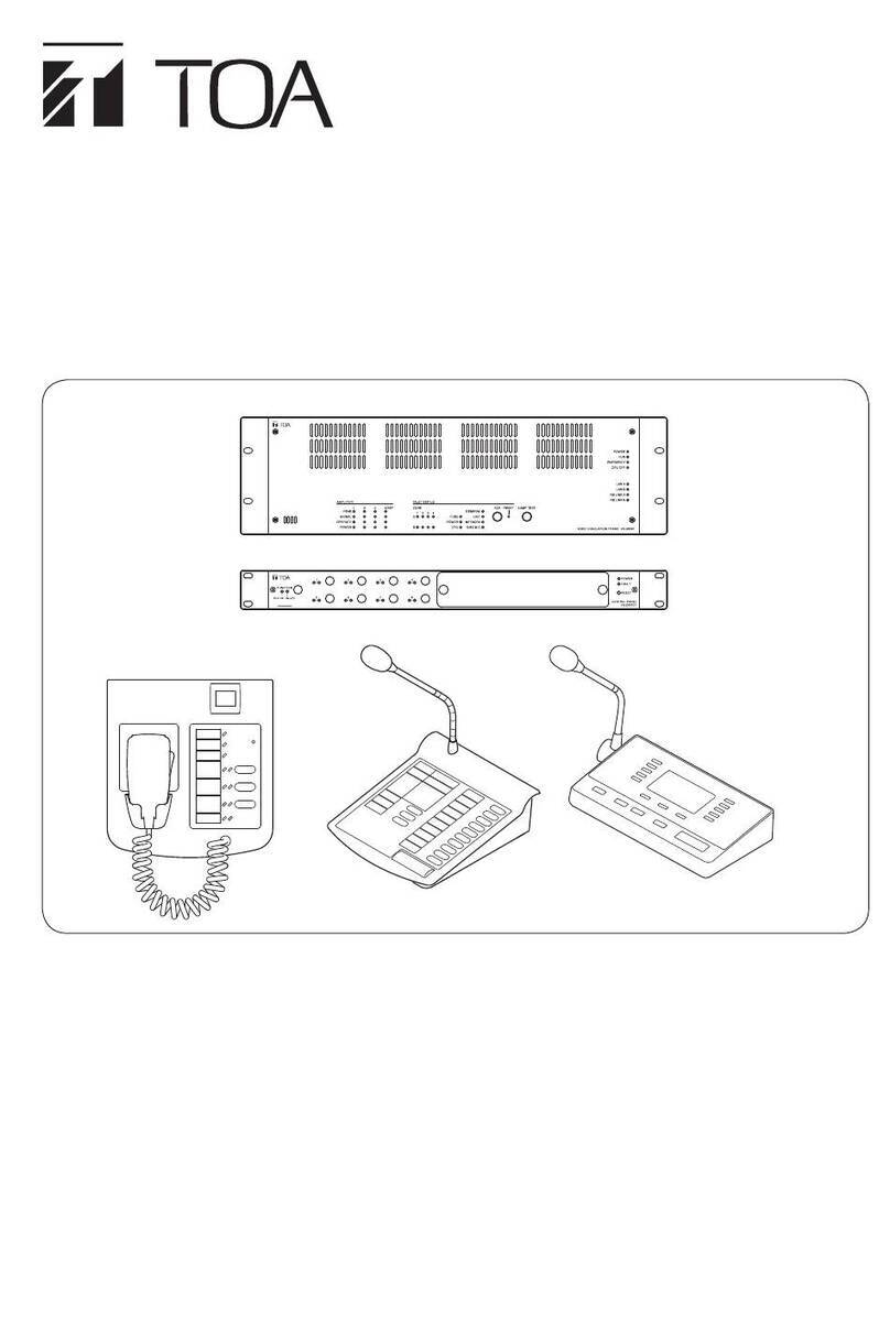
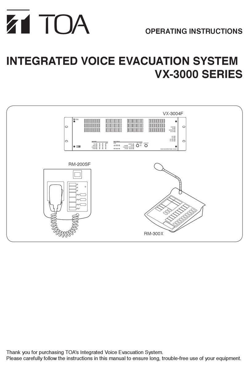
Toa VM-3000 Series User manual

OPERATING INSTRUCTIONS
Thank you for purchasing the VM-3000 Series TOA Integrated Voice Evacuation System.
Please carefully follow the instructions in this manual to ensure long, trouble-free use of your equipment.
INTEGRATED VOICE EVACUATION SYSTEM
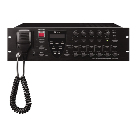
VOICE ALARM SYSTEM AMPLIFIER VM-3240VA
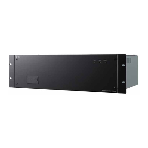
VM EXTENSION AMPLIFIER VM-3240E
REMOTE MICROPHONE RM-200M
VM-3000 Series
Note: Refer to the VX-2000DS Instruction Manual for installation instructions relating to installation of the
VX-2000DS Emergency power supply.
for Mass Notification Installations

2
TABLE OF CONTENTS
1. GENERAL DESCRIPTION .............................................................................. 5
2. FEATURES ............................................................................................................5
3. SYSTEM CONFIGURATION ........................................................................... 8
4. NOMENCLATURE AND FUNCTIONS
4.1. VM-3240VA Voice Alarm System Amplifier ..................................................... 10
4.2. VM-3240E VM Extension Amplifier .................................................................. 10
4.3. RM-200M Remote Microphone ........................................................................ 16
5. MAKING GENERAL BROADCASTS
5.1. Making Broadcasts from the VM-3240VA
5.1.1. BGM broadcasts ..................................................................................... 18
5.1.2. Microphone announcements .................................................................. 19
5.2. Broadcasting from the RM-200M
5.2.1. Microphone announcements .................................................................. 21
5.2.2. Automatic announcement broadcasts .................................................... 22
5.3. Making Automatic Announcements Using Control Signal Inputs ..................... 23
5.4. Summary of General Broadcast Procedures
5.4.1. Making general broadcast from the VM-3240VA ................................... 24
5.4.2. Making general broadcasts from the RM-200M Remote Microphone ... 24
5.4.3. Broadcasting automatic general announcements
using the control signal input ................................................................. 24
6. MAKING EMERGENCY BROADCASTS .................................................. 25
6.1. Making Emergency Broadcasts from the VM-3240VA
6.1.1. Microphone announcements .................................................................. 26
6.1.2. Automatic emergency announcement broadcasts ................................. 28
6.2. Summary of Emergency Broadcast Procedures .............................................. 30
7. PRIORITY SETTINGS
7.1. General Broadcast Priorities ............................................................................ 31
7.2. Emergency Broadcast Priorities ....................................................................... 32
8. CPU OFF FUNCTION
8.1. What Is the CPU OFF Function? ..................................................................... 32
8.2. Making All-Zone Calls Using the CPU OFF Function ...................................... 32
9. SURVEILLANCE
9.1. What Is the Surveillance Function? .................................................................. 33
9.2. How to Use the Surveillance Function ............................................................. 33
9.3. Monitored VM-3000 System Components ....................................................... 33
9.4. Equipment Operation upon Failure Detection and Recovery Procedure ......... 34
9.4.1. Equipment operation upon failure detection ........................................ 35
9.4.2. Failure acknowledgment ...................................................................... 36
9.4.3. Failure reset operation ......................................................................... 37

3
9.5. Examples
9.5.1. Failure example 1: Communications failure ......................................... 38
9.5.2. Failure example 2: Short circuit of speaker line 6 ................................ 39
9.6. LCD Failure Messages ..................................................................................... 41
10. SETTINGS
10.1. Keys Used for Settings ................................................................................... 44
10.2. Setting Hierarchical Chart .............................................................................. 45
10.3. Configuration Settings
10.3.1. Configuration settings hierarchical chart ............................................ 46
10.3.2. Password entry .................................................................................. 47
10.3.3. Configuration setting items ................................................................ 48
10.4. Information Settings
10.4.1. Information setting hierarchical chart ................................................. 58
10.4.2. Information setting items .................................................................... 58
10.5. Audio Settings
10.5.1. Audio settings hierarchical chart ........................................................ 60
10.5.2. Audio setting items ............................................................................. 61
10.6. Surveillance Settings
10.6.1. Surveillance setting hierarchical chart ............................................... 65
10.6.2. Surveillance setting items .................................................................. 65
10.7. Inputs 1 – 3 Settings
10.7.1. Inputs 1 – 3 setting hierarchical chart ................................................ 66
10.7.2. Inputs 1 – 3 setting items ................................................................... 67
10.8. BGM Settings
10.8.1. BGM setting hierarchical chart............................................................ 68
10.8.2. BGM setting items .............................................................................. 69
11. RM-200M REMOTE MICROPHONE SETTINGS
11.1. DIP Switch Functions ..................................................................................... 70
11.2. Unit ID Number Settings (Switches 1 and 2 operation) .................................. 70
11.3. Talk Key Settings (Switch 4 operation) .......................................................... 70
11.4. Compression Settings (Switch 6 operation) ................................................... 70
12. INSTALLATION
12.1. Installing the RM-200M on a Wall .................................................................. 71
12.2. Creating Remote Microphone Name Labels
12.2.1. Inserting the name label ..................................................................... 72
12.2.2. If the name label is not printed correctly ............................................ 73
12.2.3. Dimensional diagram for printing devices .......................................... 73
12.2.4. Pattern paper for hand writing ............................................................ 74
12.3. Rack Mounting ............................................................................................... 76
13. CONNECTIONS
13.1. Removable Terminal Plug Connection ........................................................... 77
13.2. Audio and Control Connection Example ........................................................ 78
13.3. RM-200M Remote Microphone Connections
13.3.1. Power supply from VM-3240VA or VM-3240E .................................. 80
13.3.2. Link connection to VM-3240VA .......................................................... 80

4
13.4. General Control Input Terminal Connections
13.4.1. Controlling functions assigned to the General Control
Input terminals from the external equipment ...................................... 81
13.4.2. Using the local input ........................................................................... 82
13.4.3. Example of connection to external equipment ................................... 83
13.5. Emergency Control Input Terminal Connections ........................................... 84
13.5.1. External emergency control equipment connection ........................... 85
13.5.2. Connections to detect failures on the emergency
control input lines ............................................................................... 86
13.6. Status Output Terminal Connections ............................................................. 88
13.7. Power Amplifier and Speaker Connections .................................................... 95
13.8. Connections between VM Amplifiers ............................................................. 96
13.9. Connecting Power Supply Equipment ............................................................ 97
14. VM-3000 CABLE USAGE TABLE................................................................ 99
15. SPECIFICATIONS
15.1. VM-3240VA Voice Alarm System Amplifier ................................................ 101
15.2. VM-3240E VM Extension Amplifier ............................................................. 103
15.3. RM-200M Remote Microphone ................................................................... 104

5
1. GENERAL DESCRIPTION
The VM-3000 Series Voice Alarm System is an integrated emergency/general announcement broadcast
system. The VM-3240VA Voice Alarm System Amplifier plays the central role in the system. Using this
amplifier in conjunction with the VM-3240E VM Extension Amplifiers allows larger systems to be built.
2. FEATURES
•The VM-3240VA has 6 speaker outputs. This can be expanded to up to 60 outputs by combining the VM-
3240E amplifiers.
•Set data, log data and other Voice Alarm System Amplifier data can be accessed by Ethernet connection for
maintenance or installation.
•Up to 4 general broadcast-use RM-200M Remote Microphones can be connected.
•For systems employing the VX-2000DS Emergency Power Supply, only emergency broadcasts can be
made while backup power is being supplied by the VX-2000DS to preserve battery reserves.
•Settings can easily be performed from a PC using the intuitive setting software.
•Audio inputs include 4 mic/line inputs, a remote microphone input, BGM inputs 1 & 2 (select either of the 2)
and internal 6 General EV messages storage.
•Control inputs and outputs include 8 general control inputs. 6 Emergency Control inputs and 3 status outputs
are provided for emergency broadcasts. By adding extension amplifiers (up to 9 units can be connected), the
number of general control inputs can be increased up to 80.

6
System: In-building Mass Notification Systems for voice evacuation.
•Autonomous Control Unit (ACU): VM-3240VA
•Number of ACUs: Single interface on the VM-3240VA.
•The wiring should be connected as follows:
VM LINK between VM-3240VA and VM-3240E
DS LINK between VM-3240VA/E and VX-2000DS
•Class B wiring: SP OUTPUT, CTRL IN, EMERGENCY CONTROL IN1, IN2, STATUS OUT
•All circuits expect SP OUTPUT are Power Limited.
•At least one set of VX-2000DS and batteries should be used to provide secondary power supply
for emergency purposes and be installed in the same rack as the VM-3240VA and/or VM-3240E.
•The RM-200M cannot be used for Emergency purposes.
•SP OUTPUTs are supervised and the RM1/2 LINK and DC22 V OUT are not supervised.
•The audio inputs of input 1 – 4, BGM, and RM-200M, and the audio sources of the built-in General EV
1 – 6 cannot be used for Emergency purposes.
•The VM-3240VA should be installed in the following locations:
(1) Within a key-locked cabinet or rack with physical security level 1 or higher
(2) In a controlled access room with a minimum access control security level 1.
Front-mounted controls should only be changed by Authorized Personnel.
•The system is provided with a Communication Security Level 0, which indicates no Security Level
employed.
•RM-200M should be installed in the same room or within 20 ft (6.1 m) of the equipment rack unless
CAT5 UL listed transient suppression devices (Tripp Lite DSUT1CSU or equal) is installed on both
ends of the RM LINK.
•The following wiring connections are intended to be made in the same room within 20 ft (6.1 m) of
each other and are enclosed within conduit or equivalently protected against mechanical damage.
EMERGENCY CONTROL IN and CTRL IN between VM-3240VA or VM-3240E and Fire
Alarm Control Panel or Notification Appliance Circuits.
VM LINK between VM-3240VA and VM-3240E.
STATUS OUT between VM-3240VA or VM-3240E and Fire Alarm Control Panel or Notification
Appliance Circuits
CTRL IN between VM-3240VA or VM-3240E and audio sources.
•Password must be set (refer to p. 48).
•BGM Volume must be set to lower than 70%.
•The FACP and TOA MNS units need to be installed adjacent to each other.
•The system is not to be used in buildings providing Suppression Service (Systems using Halon, etc.).
Sprinkled systems are allowed.
Installation for Listed/Certified UL2572 and CAN/ULC-S576 Mass Notification Systems

7
•Use Listed Lowell Manufacturing Rack, Model LER1822, or an equivalent Listed Rack with the
following minimum ventilation openings:
Fully perforated Front and Back door that has a minimum 90% of the surface area provided with
perforated openings.
Top Enclosure of the rack shall be provided with a ventilation openings that cover a minimum
surface area equal to 40% of the overall top enclosure surface area.
The side enclosures of the rack shall be provided with minimum ventilation openings located at
the upper 1/3 and lower 1/3 of each of the side enclosure, each set of ventilation openings shall
cover a minimum surface area equal to 8% of the overall side enclosure surface area.
•Use the following UL2572 listed NAC Extenders or an equivalent.
Edward Booster Power Supplies;
Models APS6AC, APS10AC
Auxiliary Power Supplies;
Models BPS6A, BPS6AC, BPS10A, BPS10AC, BPS6A/230, BPS10A/230, BPS6CAA,
BPS10CAA, MIRBPS6A, MIRBPS6AC, MIRBPS6A/230, MIRBPS10A, MIRBPS10AC,
MIRBPS10A/230, XLS-BPS6A, XLS-BPS6A/230, XLS-BPS10A, XLS-BPS10A/230, EBPS6A,
EBPS6A/230, EBPS10A, EBPS10A/230, ZBPS6A, ZBPS6A/230, ZBPS10A, ZBPS10A/230,
BPS6CAA
Remote Booster Power Supplies;
Models APS6A, APS6A/230, APS6CAA, APS10A, APS10A/230, APS10CAA, MIRAPS6A,
MIRAPS6A/230, MIRAPS10A, MIRAPS10A/230, XLS-APS6A, XLS-APS6A/230, XLS-APS10A,
XLS-APS10A/230, EAPS6A, EAPS6A/230, EAPS10A, EAPS10A/230
•In the case where MNS is lower priority than FACP, the FACP active common alarm relay of the
FACP must connect to the Emergency RESET input of VM-3000.
MNS cannot resume until the FACP is reset and initiated manually at the VM-3000.
This functionality is only permitted for a life safety system that consists of a single ACU and FACP
with no voice and the ACU does only ALL Zone Broadcast during MNS Event.
•UPS should be located in the same room as the equipment it is powering.
UPS must be hardwired to the branch circuit and hardwired to the MNS Rack and any other MNS
Device if powered by the UPS.
The connection between the UPS and the MNS Rack and any other MNS Device shall in conduit and
not exceed 20 ft (6.1 m), or equivalently protected against mechanical damage.
•For Canadian Installations the NAC Extender provide 2 hours of alarm condition.
If 2 hours loading exceeds the NAC Extender Battery capacity, the unit needs to be powered by the
UPS.
8
• Sample System 1
This example is ideal for installation in facilities and churches does not need the FACP.
•A 200 W integrated emergency/general broadcast system with 6 outputs.
•Emergency broadcasts can be made even during power failures. However, general broadcasts are not
possible.
Lead-acid Battery
VX-2000DS
RM-200M
Notification Appliance Circuit
VM-3240VA
DC POWER
RM LINK 1
DC POWER
DS LINK
STATUS OUT EMERGENCY CONTROL IN
3. SYSTEM CONFIGURATION

9
Lead-acid Battery
VX-2000DS
VM-3240E
VM-3240E
RM-200M
RM-200M
Fire Alarm Control Panel
Notification Appliance Circuit
VM-3240VA
DC POWER
DC POWER
VM LINK
RM LINK 1
RM LINK 2
DC POWER
DS LINK VM LINK
STATUS OUT EMERGENCY
CONTROL IN
STATUS OUT EMERGENCY CONTROL IN
• Sample System 2
This example is ideal for installation in large stores applied to the FACP with FACP-Strobe for FACP use only
and separate MNS-Strobe for MNS use only.
•A 600 W integrated emergency/general broadcast system with 18 outputs.
•Emergency broadcasts can be made even during power failures. However, general broadcasts are not
possible.

10
1 23
4
5 6
7
8
9
10 11
12
13
14
15 16
17
19 20 21 22 23 24 25 26 27
27
28 29 30
30
31
32
33
16 18
2
17 18
VM-3240VA
VM-3240E
34
Common to both Voice Alarm System and Extension amplifiers.
Differing between Voice Alarm System and Extension amplifiers.
*
*For emergency use only.
4. NOMENCLATURE AND FUNCTIONS
4.1. VM-3240VA Voice Alarm System Amplifier
This amplifier functions as the central unit in the VM-3000 system and its power output is rated at 200 W.
Only one unit can be connected in the system.
The front panel-mounted LCD displays setting and operation status. The amplifier also features an automatic
message function and can play back up to 6 recorded general announcements and 2 recorded emergency
announcements. Up to 4 RM-200M general broadcast-use Remote Microphones can be connected.
4.2. VM-3240E VM Extension Amplifier
The system can be expanded by connecting up to 9 VM-3240E Extension Amplifiers. The VM-3240E is
equipped with 6 speaker line outputs. It also features 8 control inputs for general broadcasts and 6 inputs and
3 status outputs for emergency broadcasts. It is connected to the VM-3240VA via the VM Link connector.
[Front]

11
1. Power Switch
Unit is switched between operating and standby
modes each time this switch is pressed. Power is
always supplied regardless of the switch setting.
2. Live Status Indicator (green) [POWER]
Remains lit while DC power is supplied.
* As long as the DC power is connected, this
indicator remains lit even if the AC power is
switched OFF.
3. Evacuation Announcement Indicator (red)
Lights whenever an Evacuation announcement is
broadcast.
4.
Evacuation Announcement Key [EVACUATE]
Can only be used while in emergency broadcast
mode.
Pressing this key plays Evacuation tone and pre-
recorded Evacuation announcement, which are
repeatedly broadcast from the speaker output(s)
selected with the Output Selection key (33). To
stop the Emergency tone and Evacuation
announcement, hold down this key for 3 seconds
or more during emergency broadcast.
5. Emergency Activation Switch / Emergency
Indicator (red) [EMERGENCY]
Pressing this switch causes it to light and
switches the VM-3240VA emergency broadcast
mode. (No automatic announcements are made.)
When an emergency broadcast is activated by a
control input other than this switch, the switch
flashes and a buzzer sounds, disabling front
panel operation.
While flashing, this switch functions as an
emergency activation acknowledgement switch.
Pressing this switch while it is flashing causes it
to stay lit, stopping the buzzer and enabling front
panel operation. In any case, this switch goes
out once the emergency broadcast is reset.
Steady On:
Lights when the emergency mode is
activated either by this switch or by
other connected external equipment
and subsequently acknowledged and
remains lit until the emergency mode
is reset.
Flashing: Flashes when the emergency mode
is activated by external equipment
other than this switch.
6. Menu Key [MENU]
During emergency broadcasts:
Cannot be used.
During general broadcasts:
Displays the setting item menu.
During settings:
Selects the setting item.
7. OK Key [OK]
During failure indication:
Stops the buzzer when a failure is detected by
the surveillance function (functioning as a failure
acknowledgment key).*
During settings:
Functions as a confirmation key.
*For more information on surveillance functions,
refer to page 33.
8. — (Minus) Key [—]
Decreases setting value numbers.
9. Cancel Key [CANCEL]
Returns the display to the previous screen during
settings.
Pressing this switch when a failure occurs
reverts the unit back to normal mode. (Refer to
"Failure reset operation" on page 37 and
"Examples of Failures and Their Counter-
Operations" on page 38.)
10. + (Plus) Key [+]
Increases setting value numbers.
11. LCD
Backlit during unit operation.
During emergency or general broadcasts:
Displays operation and failure information.
During settings:
Used to perform settings.
12. BGM Selection Key [BGM]
Displays the BGM (background music) selection
screen on the LCD (11). The display switches
between the setting screens for Treble, Bass,
etc. with each depression of this key. (Refer to
"BGM Settings" on page 68.)
13. BGM Volume Control [BGM]
Adjusts the BGM input volume.
14. Input Selection Keys [INPUT 1 – 3]
Display key’s corresponding setting screen on
the LCD (11). The display switches between the
setting screens for Treble, Bass, etc. with each
depression of the selected key. (Refer to "Input
1 – 3 Settings" on page 66.)
15. Input Volume Controls [INPUT 1 – 3]
Adjust the input volume for Inputs 1 – 3.
16. Master Volume Control [MASTER]
Sets the output volume for the entire system.
17. VM Reset Key
For the VM-3240VA:
Resets the entire system.
For the VM-3240E:
Resets only VM-3240E Extension amplifiers.

12
18. Level Meter
Indicates the output level of the unit’s internal
amplifier.
19. Emergency Microphone
Only used while in emergency broadcast mode.
Press the Talk key located on the side of the
microphone to broadcast emergency
announcements.
20. Monitor Speaker
Buzzer tone is audible from this speaker when
the emergency mode is activated by external
equipment other than the unit’s Emergency
Activation switch (5) or when any failure occurs.
Emergency tone: Repeating the cycle of 1
second on and 1 second off
Failure tone: Repeating the cycle of 2
seconds on and 3 seconds off
21. Emergency Microphone Indicator (red)
Lights when the unit’s front panel-mounted
emergency microphone (19) is used.
22. Emergency Microphone Volume Control
Rotate clockwise to increase the emergency
microphone volume.
Rotate counterclockwise to decrease the
emergency microphone volume.
23. Reset Key [RESET]
For emergency broadcasts:
Terminates the emergency broadcast and
returns operation to the original general
broadcast.
For general broadcasts:
Resets the front panel’s output selection status.
24. Alert Announcement Start Key [ALERT]
For emergency broadcasts:
Plays Alert tone and pre-recorded Alert
announcements through the speaker output
selected with the Output Selection key (33). Holding
down this key for 3 seconds stops the broadcast.
For general broadcasts:
Used to test LED indicators. (While pressed,
LED indicators remain lit and the unit’s internal
buzzer sounds.)
25. Alert Announcement Indicator (red)
Remains lit while a recorded Alert announcement
is being broadcast.
26. Failure Indicator (yellow) [GENERAL FAULT]
(VM-3240VA only)
Flashes when a failure occurs while sounding the
internal buzzer. Pressing the [OK] key (7) stops
the buzzer and switches the indicator from
flashing to steady ON. Failure details are
displayed on the LCD (11). (When there are
multiple failures, they can be checked by moving
the screen using the [+] key (10) or [–] key (8).
Failures are not displayed on the LCD when in
setting mode. Failures are displayed or notified
after exiting the setting mode. Also, if any failure
occurs during general or emergency broadcasts,
the operation status and failure display are
alternately shown on the LCD.
27. CPU Failure Indicator (yellow) [CPU FAULT]
Lights when the CPU fails.
28. All-Zone Call Selection Key [ALL]
Simultaneously selects all speaker outputs for
general and emergency broadcasts. Press again
to reset the simultaneous selection.
When pressed, all speaker output volume
controls do not work in both general and
emergency broadcast modes.
29. All-Zone Call Indicator (green) [ALL]
Lights when an all-zone call is initiated.
30.
Speaker Output Volume Controls [OUTPUT 1 – 6]
Adjust the output volume of speaker outputs 1 – 6.
31. Emergency Broadcast Output Indicators (red)
[EMERGENCY]
Indicate the speaker outputs for emergency
broadcasts.
32. Selected Output Indicators (green) [SELECT]
Indicate the speaker outputs selected with the
Output Selection key (33).
33. Output Selection Keys
Select corresponding speaker output.
Press again to reset the selection.
For general broadcasts:
Select and reset broadcast zones.
For emergency broadcast:
Select and reset speaker outputs for emergency
broadcasts made by the unit’s front panel-
mounted emergency microphone and automatic
announcements.
34. Communications Failure Indicator (yellow)
[COM FAULT]
(VM-3240E only)
Flashes when failures are detected in
communications with the VM-3240VA.

13
35
VM-3240VA
62
36 37
40 41
42
43
44 45 46
47
48
49 50 51 52 53 54 55
56
57
54 55 57
58
59
59
60
61
38 39
VM-3240E
50 51 52 53
63 64
60
65 66 6867
35 36 37 42 44 45 4638 39
Common to both Voice Alarm System and Extension amplifiers.
Differing between Voice Alarm System and Extension amplifiers.
Not used.
49
69
*1
*1*1*1*1
*2*2*2
*2*2*2*2
*2*2
*1*1*1*1
*1
*2*2*2
*2*2
*1
*1
*1For both emergency and no-emergency use.
*2For no-emergency use only.
*1*1
*1
35. Speaker Output Terminals 1 – 6 [SP OUT
70 V LINE 1-6, H, C]
Connect speakers to these outputs.
36. External Amplifier Input [EXT. PA AMP
INPUT]
Not used.
37. AC Fuse
Use the following 20 mm type miniature fuses:
8 A (for VM-3240VA and VM-3240E)
38. Power Supply Output Terminals [VX-2000DS
ONLY, PS OUT]
Supply power to the VX-2000DS Emergency
Power Supply.
[Rear]

14
39. 24 V DC Input Terminals [VX-2000DS ONLY,
24 V POWER IN]
Connect power from the VX-2000DS Emergency
Power Supply Unit.
40. DIP switch (VM-3240VA only)
Used to perform equipment settings.
DIP Switch 1 [LINE/MIC]
Switches input sensitivity of Input 4. (ON: MIC,
OFF: LINE; Default: OFF)
DIP Switch 2 [NORMAL/EMERGENCY]
Always set this switch to OFF. (Default: OFF)
DIP Switches 3 – 5
Not used. (Default: OFF)
DIP Switches 6
Set to ON when excluding the front-mounted
emergency microphone from the surveillance
item. (Default: OFF)
DIP Switch 7 [FIRMWARE]
Set to ON when upgrading firmware version, and
OFF to prohibit update. (Default: ON)
DIP Switch 8 [CONFIG]
Set to ON when transferring set data from a PC,
and to OFF to prohibit set data transfer. (Default:
ON) (For more information on set data transfer,
refer to "Transferring Data Edited by PC between
the VM-3000VA and a PC" in the separate
software manual.)
41. BGM/Paging Recording Output Terminals
[REC OUT BGM/PAGING]
(VM-3240VA only)
Not used.
42. Status Output Terminals [STATUS OUT]
Provide the following status outputs in
synchronization with unit operation:
•Emergency status output
•Failure status output
•CPU OFF status output
43. BGM 1 & 2 Input Terminals [BGM 1, 2]
(VM-3240VA only)
Connect the BGM sound source.
(–10 dB*, 10 kΩ)
*0 dB =1 V
44. Emergency Control Input Terminals 1 – 6
[EMERGENCY CONTROL, IN 1/IN 2]
Connect to an automatic fire alarm control panel.
Contact inputs 1 – 5 are no-voltage make contact
inputs.
Input 6 is an isolated voltage input which is
activated when the polarity of the applied voltage
(24 V DC is kept applied to this terminal under
normal condition) is reversed.
45. DS Link Connector [DS LINK]
Connects to the VX-2000DS Emergency Power
Supply’s DS-SF link connector.
46. Not used.
47. Audio Input Terminals 1 – 3 [INPUT 1 – 3]
(VM-3240VA only)
Electronically-balanced 600 Ω, –10 dB* / –50 dB,
XLR/phone jack combination connectors. LINE
or MIC input can be selected, and the phantom
power supply turned on and off. (Refer to "Inputs
1-3 Settings" on page 66.) These inputs can be
converted into transformer-balanced terminals
using the optional IT-450 transformer. It is also
possible to change microphone sensitivity to –30
dB. (Refer to the separate Installation guide.)
*0 dB = 1 V
48. PA Link Connector [PA LINK]
Not used.
49. AC Input
Connects to an AC outlet using the supplied AC
power cord.
50. Attenuator Control Outputs [ATT CTRL]
Not used.
51. Direct Output Terminals [DIRECT OUT 70 V
LINE]
Not used.
52. 22 V DC Output [22 V, +, –]
Provide 22 V DC output, max. 0.3 A.
53. Functional Ground Terminal
Noise may be generated when external
equipment is connected to the unit. Connecting
this terminal to the functional ground terminal of
the external equipment may reduce the noise.
Note: This ground is not for protective ground.
54. Control Output Terminals 1 – 8 [CTRL OUT 1
– 8, G]
Not used.

15
55.
Control Input Terminals 1 – 8 [CTRL IN 1 – 8, G]
Control input terminals for general broadcasts.
Functions assigned to each contact input are
determined by software settings. (For details,
refer to "Event Settings" in the separate software
manual.)
56. Audio Input 4 Terminals [INPUT 4]
(VM-3240VA only)
Electronically-balanced 600 Ω, –10 dB* / –50 dB,
screw terminal. Use DIP switch (40) for
LINE/MIC switching.
*0 dB = 1 V
57. Remote VOL Terminals 1 & 2 [REMOTE VOL]
Not used.
58. Input 4 Volume Control
(VM-3240VA only)
Adjusts the audio input 4’s (56) input volume.
59. External Amplifier Link Connector [EXT. PA
LINK]
Not used.
60. VM Link Connector [VM Link Out]
Connects to the VM-3240E’s VM Link In
connector.
61. LAN Connector [LAN]
(VM-3240VA only)
Connects to a PC.
62. Remote Microphone Link Connectors 1 & 2
[RM1 LINK IN, RM2 LINK IN]
(VM-3240VA only)
Connect the RM-200M Remote Microphone to
these connectors.
63. DIP Switch (VM-3240E only)
Used for unit ID and equipment settings.
DIP Switches 1 & 2 [LOCAL INPUT]
Not used. Default setting: OFF
DIP Switches 3 – 6 [EXTENSION UNIT NO.]
Used for unit ID settings for the VM-3240E.
(Refer to "Connections between VM Amplifiers"
on page 96 for ID settings.)
Default settings: ON (Switch 3), OFF (Switches 4
– 6)
DIP Switch 7 [FIRMWARE]
Set this switch to ON to enable firmware version
updates, and OFF to prohibit the update.
Default setting: ON
DIP Switch 8 [CONFIG]
Not used.
Default setting: ON
64. Local Input Terminals [LOCAL INPUT]
(VM-3240E only)
Local broadcast can be made when this terminal
is used in conjunction with the Control Input
terminals (55).
For details, refer to "6. SYSTEM SETTINGS; 6.8.
Local Input Setting" in the separate software
instruction manual.).
65. Local Input Volume Control
(VM-3240E only)
Adjusts the input volume of the equipment
connected to the Local Input terminal (64).
66. LAN Connector [LAN]
(VM-3240E only)
Not used.
67. VM Link In Connector [VM LINK IN]
(VM-3240E only)
Connect this connector to the VM-3240VA’s VM
LINK OUT connector. When using two or more
VM-3240Es, connect this connector to other VM-
3240E’s VM LINK OUT.
68. Local Remote Microphone Link Connector
[LOCAL RM LINK IN]
(VM-3240E only)
Not used.
69. PA Link Connector [PA LINK]
Not used.

16
[Top]
[Rear][Side]
Not used.
11
18
12
13
14 15 16 17
1 1
234
5
6
7
89
10
4.3. RM-200M Remote Microphone
The RM-200M Remote Microphone connects to the VM-3240VA for the purpose of making general broadcast
announcements. It communicates with the VM-3240VA through its RS-485 interface. Zone selection or
automatic announcement start can be assigned to the function key using the dedicated software. No
emergency broadcasts can be made with this microphone.

17
1. Indication Label Holder
Write the name, purpose, etc. of the indicator and key
on a label and insert the label into the holder from the
top. Labels can be printed using the setting software.
(For more information, refer to "Printing Remote
Microphone Labels" in the separate software manual.)
2. Power Indicator (green)
Lights when power is supplied to the unit.
3. Communication Failure Indicator (yellow)
Flashes when a failure is detected in
communications with the VM-3240VA.
4. Not used.
Lights when the system is in emergency status.
5.
Broadcast Zone / Automatic general broadcast
Announcement Start Indicators (green)
Indicator’s function assigned to each indicator is
determined by software settings.
Broadcast Zone Indicators
Light when their corresponding zones are selected.
Automatic general broadcast Announcement
Start Indicators
Light when an automatic announcement is
started.
6. Broadcast Zone Selector / Automatic general
broadcast Announcement Start Keys
Key function assigned to each key is determined
by software settings.
Broadcast Zone Selector Keys
Select broadcast zones. Pressing the Talk key (7) after
zone selection allows microphone announcements to
be broadcast over the selected zone(s).
Automatic general broadcast Announcement Start Key
Automatic general broadcast announcements
are broadcast over the selected zone(s).
7. Talk Key
This key is used for general broadcast microphone
announcements. Pressing the Talk key after zone
selection allows microphone announcements to be
broadcast over the selected zone(s).
8. Talk Indicator (green)
Lights when the Talk key (7) is pressed.
9.
External Microphone In-Use Indicator (orange / green)
Flashes when a paging call is made from the
external remote microphone.
Orange: Indicates the mode that disables
broadcasts from the unit.
Green: Indicates the mode that allows the unit to
interrupt broadcasts from external equipment.
10. Not used.
11. Microphone
Used for making announcements.
12. DIP Switch
Used to set the unit ID number and equipment
functions. (Refer to "DIP Switch Functions" on
page 70.)
Switches 1 and 2
Set the ID number of the Remote Microphone.
Default setting: ON
(Refer to "Unit ID Number Settings" on page 70.)
Switch 3
Not used.
Default setting: ON
Switch 4
Sets the Talk key’s operating system.
Default setting: ON
(Refer to "Talk Key Settings" on page 70.)
Switch 5
Not used.
Default setting: ON
Switch 6 [COMPRESSION]
Enables/disables compression.
Default setting: ON
(Refer to "Compression Settings" on page 70.)
13. RM-210 Connector [Extension]
Not used.
14. Power Supply Input Connector
The VM-3240VA or VM-3240E can supply power
to one RM-200M Remote Microphone. Connect
a power supply to this connector.
15. Link Connector (RJ45 Connector)
Connects to the VM-3240VA’s or other RM-
200M’s LINK connector.
16. Not used.
17. Microphone Volume Control
Adjusts the volume of the unit’s microphone (11).
Rotate clockwise to increase the microphone volume.
Rotate counterclockwise to decrease the
microphone volume.
18.
External Microphone Input Jack (3.5 mm mini jack)
An electret condenser microphone can be connected
to this terminal. Connecting a microphone to this jack
disables the unit’s microphone (11).

18
5. MAKING GENERAL BROADCASTS
5.1. Making Broadcasts from the VM-3240VA
5.1.1. BGM broadcasts
Broadcast musical programs from the BGM sound source connected to BGM input terminals 1 or 2 located on
the rear panel of the VM-3240VA. Adjust the BGM volume control and the volume control of the designated
speakers to an appropriate sound level in advance.
Step 1. Press the BGM selection key. The "Select BGM"
screen will be displayed on the LCD.
Step 2. Select either BGM 1 or BGM 2 with the [+] or [–] key.
Step 3. Press the [OK] key to confirm the selected BGM
program.
Step 4. Press the all-zone call key or output selector key to
select the broadcast zone, then begin the BGM
broadcast.
•Pressing the all-zone call key causes the all-zone
call indicator to light green, enabling BGM
broadcasts over an entire area.
•Pressing an output selector key causes the
selected output’s indicator to light green, allowing
the BGM program to be broadcast over the
corresponding zone.
Step 5. To terminate the BGM broadcast, press either the
all-zone call key or output selector key again. The
indicator goes out and the BGM broadcast is
terminated.
All-zone call key
All-zone call indicator Output selector key
Output indicator
BGM selection key
BGM volume control
LCD screen
[–] key
and
[+] key
OK key
[VM-3240VA]
SELECT B
G
M
B
G
M
1
B
G
M
B
G
M
2
B
G
M
B
G
M
2
SELECT B
G
M
B
G
M
2
Select BGM screen
Select BGM screen
or
or
Normal status
BGM
1
BGM in-progress
screen
OK
3
BGM in-progress
screen
ALL OUTPUT 1 – 6
4
–+
2

19
All-zone call key
All-zone call indicator
Output selector key
Output indicator
[VM-3240VA]
Set the priority level of the audio input terminal to which the microphone is connected to "7" (MIX). (Refer
to "General Broadcast Priorities" on page 31 for priority levels, and to "Priority Settings" in the separate
software manual for how to set priorities.)
5.1.2. Microphone announcements
Make voice broadcasts using the microphone connected to any of audio input terminals 1 – 4 located on the
rear panel of the VM-3240VA. Perform input sensitivity settings (Line/Mic selection) while viewing the LCD.
(Refer to "Input 1 – 3 Settings" on page 66.) Also, adjust the volume control for the input the microphone is
connected to (Inputs 1 – 4) and the speaker output volume control for the broadcast zone to an appropriate
volume in advance.
Note
The microphone on the front panel is intended for emergency broadcasts only. It cannot be used for general
broadcasts.
[Front panel-mounted key operation for microphone announcements]
Perform the following setting in advance using the setting software:
Step 1. Press either the all-zone call key or output selector key to select the broadcast zone.
•Pressing the all-zone call key causes the all-zone call indicator to light green, enabling microphone
announcement broadcast over an entire area.
•Pressing an output selector key causes the selected output’s indicator to light green, allowing the
microphone announcement to be broadcast over the corresponding zone.
Step 2. Make a microphone announcement using the microphone connected to the audio input terminal on
the rear panel.
Step 3. To terminate the microphone announcement, press the all-zone call key or the same output selector
key again.
The corresponding indicator goes out, terminating the microphone announcement.

20
[Making microphone announcements by activating control inputs]
Perform the following settings in advance using the setting software:
Step 1. Close ("Make") the Control Input terminals on the rear panel of the VM-3240VA.
Step 2. Make a microphone announcement using the microphone connected to the audio input terminal on
the rear panel.
Step 3. To terminate the microphone announcement, open ("break") the Control Input terminals.
The corresponding indicator goes out, terminating the microphone announcement.
The corresponding all-zone call or output indicator lights green, allowing microphone announcements
to be broadcast from the corresponding speaker line.
All-zone call indicator Output indicator
[VM-3240VA]
Microphone talk switch
[Example]
Setting microphone announcement activation for Control
Input Terminal 1.
Control Input terminals
[VM-3240VA]
•Set the priority level of the audio input terminal to which the microphone is connected to any of "1" – "6".
(Refer to "General Broadcast Priorities" on page 31 for priority levels, and to "Priority Settings" in the
separate software manual for how to set priorities.)
•Perform settings so that a microphone announcement is broadcast over designated broadcast zones
when the control input terminal is activated. (For more information, refer to "General Control Input
Settings" in "Event Settings" in the separate software instruction manual.)
Other manuals for VM-3000 Series
2
This manual suits for next models
3
Table of contents
Other Toa Security System manuals

Toa
Toa Netcansee N-VR2010 User manual

Toa
Toa Netcansee N-CC2360 User manual

Toa
Toa Netcansee N-VR2010 User manual

Toa
Toa VX-2000 Series Guide

Toa
Toa VM-3000 Series User manual

Toa
Toa VM-3000 Series User manual

Toa
Toa VX-3000IM-EB User manual

Toa
Toa C-CC364 Manual

Toa
Toa VX-3308WM User manual

Toa
Toa RS-150 User manual