H7E-P
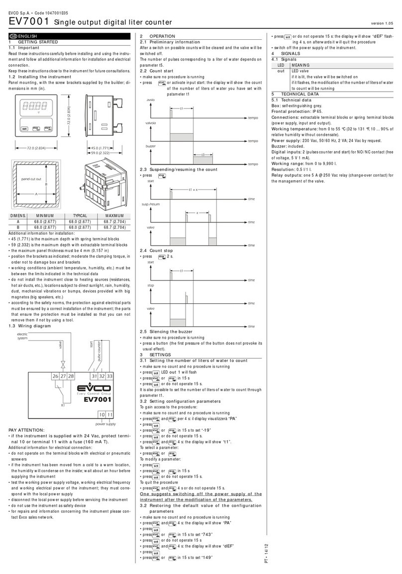
H7E-P
4
Connections
■H7EC-P, H7EC-PL, H7ET-P ■H7ER-P, H7ER-VP, H7ER-V2P
Power supply
All H7E❑-❑P models require a 3 VDC external power source.
When designing a circuit, plan the power wiring connections to
be within 50 mm (1.97 in). Refer to the connection diagrams
above for proper wiring polarity.
The life expectancy of a battery power source can be calcu-
lated by the following formula:
t = 1000 A/lc
where, t: life expectancy of battery (h)
A: battery capacity (mAh)
lc: current consumed by H7E❑-❑P (µA)
Voltage division of power source circuit
When necessary, the voltage from the battery may be divided
by resistances:
When doing so, however, ensure that the following equation
balances:
E (V) x R2/ (R1+ R2) = 3V
Allow a current high enough to flow through R1so that the
H7E❑-❑P receives adequate current.
C is a film capacitor, of about 0.1 µF, and is intended to absorb
noise superposed from the power lines.
Keep wiring between the H7E❑-❑P and R2as short as
possible, within 50 mm (1.97 in).
Use a diode (Di) having a forward voltage as small as possible
(0.1 V max. at IFof 1 mA). Determine the ratio of R1to R2in
accordance with the forward voltage of the diode to be used.
Be aware that when the supply voltage of power source E has
dropped to less than the voltage of the backup circuit, the
battery discharges. To protect the circuit against a momentary
power failure, an aluminum electrolyte capacitor can also be
used in place of a battery, as shown below:
When the capacitor is used, its backup time can be calculated
by the following formula*:
t = C(V1-V2)/lc
where, t: Backup time (s)
C: Capacitance (µF)
V1: Supply voltage before power failure (V)
V2: Minimum operating voltage of H7E❑-❑P (V)
lc: H7E❑-❑P current consumption (µA)
*In all applications which require the counter to maintain the
accumulated display for a longer time, increase the capaci-
tance to an appropriate value.
Input connection
Contact input
Backup circuit for protection against power failure


