Toky DW9L Series User manual
Edition and modification record
Date
2022.01.10
Version
F/0
Modify content
First File
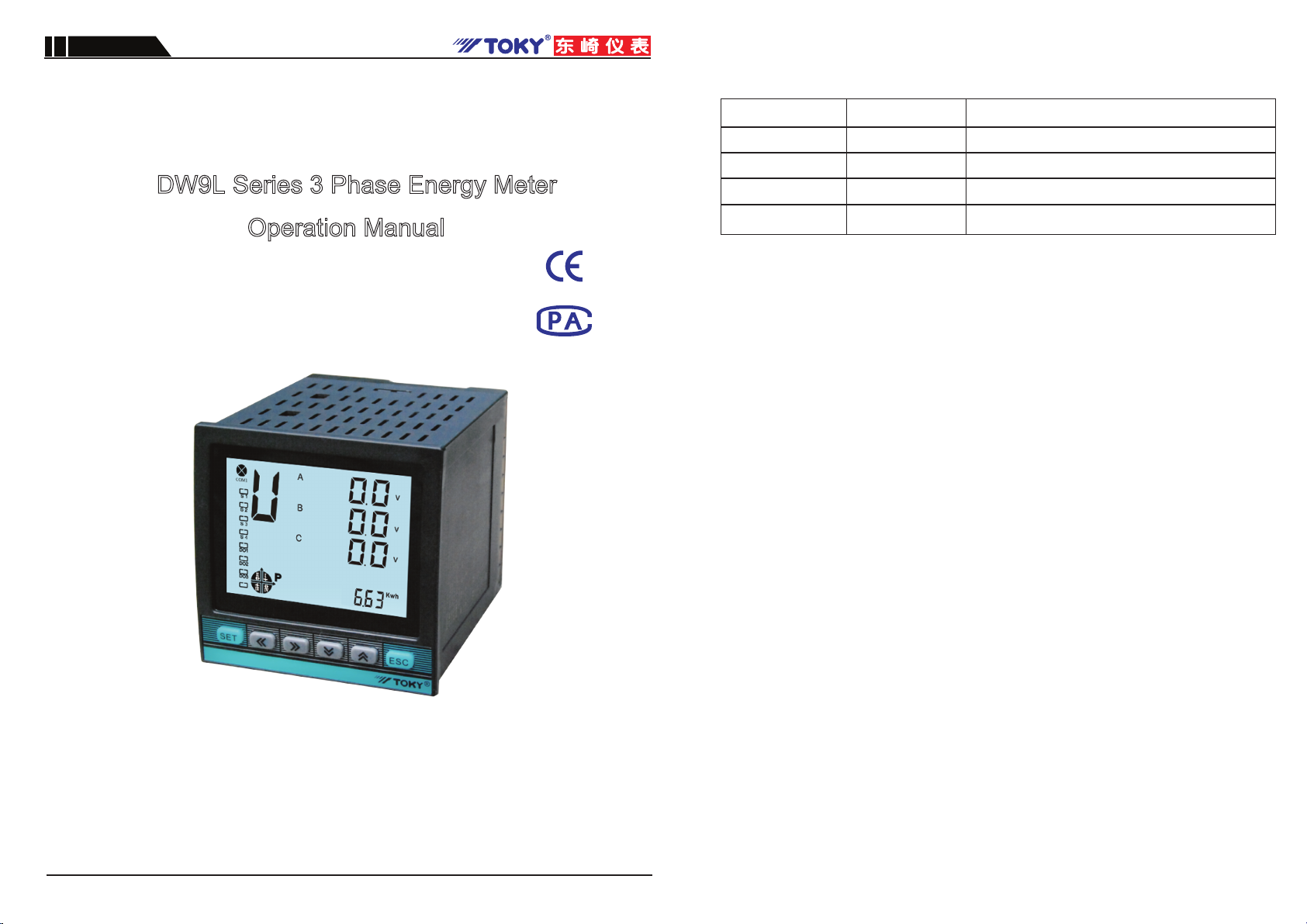
DW9L Series 3 Phase Energy Meter
Operation Manual
DW9L Series
National High-tech Enterprise/National Standard Drafting Unit
KKDW9L-F02E-A/0-20220110
Hot line:400-0760-168
Site:http://www.toky.com.cn
Toky Electrical Co., Ltd

Index
1 Product overview
1.1 This instrument implements relevant national standards
1.2 Features and applications
1.3 Product function list
1.4 Measurement parameters
2 Technical indicators
3 Installation and wiring
3.1 Loading list
3.2 Shape and installation hole size
3.3 Installation method
3.4 Terminal diagram
3.5 Terminal corresponding wiring table
3.6 Signal wiring diagram
3.7 Auxiliary power supply
3.8 Relay output
3.9 Switch input
3.10 Analog transmission output
3.11 Energy pulse output
3.12 Communication output
4 Operation instructions
4.2 Display area description
4.1 Panel diagram
4.4 26 English letters display method on LED
4.3 Key button description
4.6 Menu modification instructions
4.5 Measurement display page description
4.8 Multi-rate setting instructions
4.7 Menu modification example
4.9 Alarm output and transmission output parameter
5 Simple troubleshooting
6 Event record description
6.1 Event type
6.2 Event record format
6.3 Reading event records
1
1
2
2
3
4
4
4
4
4
5
6
7
7
7
7
7
8
8
8
8
8
9
9
10
12
13
14
15
15
15
14
15
1
8.1 Overview 23
8 DLT645 communication description 23
7.3 Power meter communication address mapping 18
7.2 Communication frame format description 16
7.1 MODBUS-RTU protocol Introduction 16
7 Communication protocol description 16
8.2 DLT645 communication address correspondence table 23
This equipment can only be installed by professional staff. The manufacturer will not be responsible
for any damage caused by failure to follow the instructions in this manual.
Note:
Risk of electric shock, burning or explosion
!
!
Thank you for choosing our products. In order to facilitate you to use this instrument safely, correctly and
efficiently, please read this manual carefully and pay attention to the following points when using it.
※Equipment can only be installed and maintained by qualified personnel.
※Before making any operation, isolate the voltage input and power supply, and short-circuit the
secondary windings of all current transformers.
※Using a suitable voltage detection device to confirm that the voltage has been cut off.
※Before the equipment is powered on, all mechanical parts, doors and covers should be returned
to their original positions.
※Provide correct rated voltage to the meter when using it.
Any operation not following the manual will cause accident or
damage to the product !
Information provided in this manual can be modified without prior notice.
The company reserves the right of information updation.
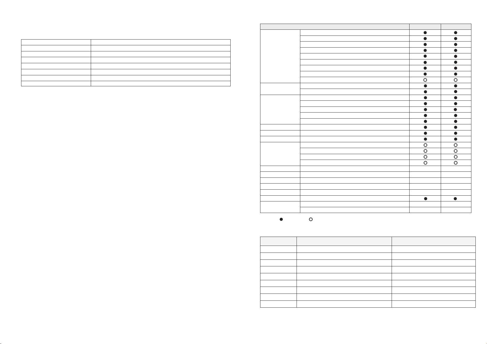
Remark: “ ” standard ; “ ” optional
2
1.3 Function List
1.4 Measurement Parameter Range
Note: Energy metering is a secondary-side value. Please multiply the PT and CT values when you measure
the electric energy.
Indirect Measurement Range
Measurement
Parameter Accuraccy
2.0V~500KV
Voltage 0.2%
0.02A~6000A
Current 0.2%
1W~100MW (negative consistent)
Active Power 0.5%
1var~1000Mvar ( negative consistent)
Reactive Power 0.5%
1VA~100MVA
Apparent power 0.5%
-1.000~1.000
Power Factor 0.5%
30Hz~500Hz
Frequency 0.2%
0~999999.99kWh(note)
Active Energy 0.5%
Reactive Energy 2%
2
1
4
2
1
92*92mm
96*96*100mm
DW9L-IRC38
2
No
4
2
1
92*92mm
96*96*100mm
DW9L-RC38
Function
Real-time
measurement
3 phase voltage
Grid Frequency
3 phase current
Zero phase current
3 phase active power
3 phase reactive power
3 phase apparent power
3 phase power factor
Positive sequence,negative sequence,zero sequence
Active Power
4-quadrant reactive power
Total Harmonic Content
32nd times harmonics content rate of voltage
32nd times harmonics content rate of current
Maximum value of voltage and current
Unbalance of voltage and current
Energy
Measurement
Power Quality
4 tariff rates, 12 time periods measurement
Active Power, reactive Power, maximum demand record
With real-time clock which can be timed
Multi-rate
Demand
Clock
Undervoltage, overvoltage, undercurrent, overcurrent
Alarm Action
Programming parameters
Clear energy, demand, etc.
Event Record
1 loop active energy, 1 loop reactive energy
One 4~20mA analog output
Passive dry contact
Energy Pulse
Analog Output
Alarm Output
Communication
AC250V/5A Remote control/ alarm
RS485: support MODBUS-RTU/DLT645-2007
Large size LCD display
Hole Size
Dimensions
Size
Display
DI (digital input)
1
1
I. Product Description
1.2 Features and Application
1.1 The instrument implements relevant national standards
DL/T 614-2007
GB/T 17215.301-2007
GB/T 17215.322-2008
GB/T 17215.323-2008
DL/T 645-2007
GB/T 15284-2002
GB/T 14549-1993
GB/T 15543-2008
<Multi-function Energy Meter>
<Multifunction Harmonic Meter Special Requirements>
< 0.2 and 0.5 Class Static AC Active Power Meter>
< 1 and 2 Class Static AC Reactive Power Meter>
<Multi-function Energy Meter Communication Protocol>
<Multi-tariff rate electric energy meter special requirements>
<Admissible three-phase voltage unbalance>
<Power quality public grid harmonics
This instrument with high performance-price ratio, can directly replace common measurement indication
meter, energy meter, harmonics measure instruments ect. As an advanced intelligent and digital power
grid front-end acquisition component, it can be used in various control systems . It has features of easy
to install, simple wiring, easy maintenance, small enginnering quantity, field programmable input
parameters etc, also can communicate with various PLC, industrial control computers.
Main Features:
※Large size LCD display, simple and convenient operation, rich interface information;
※Measure parameters such as U, I, P, Q, S,P, F,Hz etc.
※With 4-quadrant reactive power record function;
※Measure forward and reverse energy, realizing 12 time periods multi-rate energy metering;
※With demand statistics function, support U, I maximum value record function;
※Measure the 2-31 harmonics content and total harmonic distortion rate THD of voltage and
current in power network
※Measure voltage and current unbalance and other power grid quality parameters;
※Support 4 digital input (DI) function, adopts dry contact signal input mode
※Support 2 relays (250V/5A) digital output (DO) function,
output and remote control in various places;
※Support one loop active energy pulse, one loop reactive energy pulse output;
※Support One RS485 communication, MODBUS-RTU communication procotol
( optional DLT645 protocol);
※Optional one 4-20mA analog output;
Typical Application:
※Energy Management System ※Power Monitoring System
※Intelligent Building ※Smart Switchboard
※High and low voltage switch cabinet ※Distribution network automation

3.1 Loading List
Meter Mounting brackets Instructions
1( PC ) 1(Set)1(PC)
Certification
1(PC)
4
III. INSTALLATION AND WIRING
3.3 Installation method
(as shown in the right figure)
1) Open 92*92 (mm) hole in fixed distribution cabinet;
2) Remove the meter and take out the fixed bracket;
3) The instrument is pressed into the mounting hole from the front;
4) Insert the instrument holder and tighten the screws to secure the
meter
3.2 Shape and mounting hole size
Model
(mm)
96×96
Case Size
(mm)
91×91
Hole Size
(mm)
92×92+0.5
Length(mm)
100
Minimum installation distance
120
Horizontal Direction
120
Vertical direction
91.3
104.6
99.0
5.6
Side SizePanel Size
96.0
96.0
Power Meter
SET E SC
3
4
DO1
DO2
DO3
P
DO4
v
v
v
B
A
C
COM1
This Sharp
Peak
Flat
THD
Unbl
MAX
Last
I II
Valley
Month
3.4 Instrument terminal diagram
Rear view
1
2
3
4
5
6
7
8
9
0
L(+)
N(-)
NO
NC
ACOM
NO
NC
AO+
AO-
10
11
12
13
14
15
16
17
18
19
B-
A+
COM
S1
S2
S3
S4
RP
AP
PCOM
20
21
22
23
24
25
26
27
28
29
Ua (Ua)
Ub
Uc (Uc)
Un (Ub)
IA*
IA
IB*
IB
IC*
IC
92.0mm
92.0mm
3
II.Technical Parameters
Input
Measurement
Display
AC 0.02-6A
50-60Hz,a
ccuracy 0.01Hz
AC/DC 100V~240V
<8VA
-10~55℃
-20~75℃
Item Performance parameters
Network
Rated value
Overload
Power Consumption
Accuracy
AC3x220V/380V
3 phase 4 wires/ 3 phase 3 wire/ Single phase
Continuous:1.2 times Instantaneous:2 times/2s
<0.6VA (each phase)
>500kΩ
RMS measurement, Accuracy 0.2%
Voltage
Impedance
Rated Value
Overload
Power Consumption
impedance
Accuracy
Continuous: 1.2 times Instantaneous: 2 times/2s
<0.4VA (each phase)
<20mΩ
RMS measurement, Accuracy 0.2%
Current
Frequency
Power
Harmonic
Energy
Clock
Display
Power Supply
Consumption
Current
Active, reactive, apparent power, accuracy: 0.5%
Power, Harmonic Accuracy: A
Active power: accuracy 0.5S; reactive power: accuracy 2
Clock error:0.5s/d (Reference temperature:23℃)
Large screen segment LCD display
Communication
1. RS485 Communication;
2. Correspond internation standard MODBUS-RTU protocol
3. Correspond national standard DLT645-2007 protocol;
4. Communication Baud Rate: 1200,2400,4800,9600,19200;
5. Checking Method: optional no parity, even parity, odd parity
Pulse
Alarm Output
Analog Output
Digital Input (DI)
Passive optocoupler collector output
Relay output: capacity: 5A/250VAC or 5A/30VDC;
programmable alarm or remote control mode;
4-20mA current analog output
Remote signal: passive dry junction input
Output
Working Environment
Storage Environment
Insulation
Input and power >2kV, Input and output>2kV
Input, output, Power Supply VS Case>50MΩ
Environment
Safety Withstand voltage
Electrostatic discharge
immunity
Electrical fast pulse
group immunity
Surge immunity
RF conducted immunity
Power frequency
magnetic field immunity
Radiation immunity
Correspond GB/T 17626.2-2006 3 level
Correspond GB/T 17626.4-2008 4 level
Correspond GB/T 17626.5-2008 4 level
Correspond GB/T 17626.6-2008 4 level
Correspond GB/T 17626.8-2006 4 level
Correspond GB/T 17626.3-2006
Electromagnetic
Compatibility

5
3.5 Terminal corresponding wiring chart
Description
1.The brackets in the voltage input terminal indicate the 3 phase 3 wires connection
2.The current "*" is the current input terminal, all outgoing lines must be unified.
Otherwise,the measurement will be inaccurate.
3.If there is any change in the wiring, please take the wiring diagram of the instrument case as the standard.
Energy Pulse
Voltage Signal
Input
Current Signal
Input
17
18
19
20
21
22
23
24
25
26
27
28
29
RP
AP
PCOM
UA (Ua)
UB
UC (Uc)
UN (Ub)
IA*
IA
IB*
IB
IC*
IC
Reactive energy pulse poer
Active energy pulse port
Pulse output common port
3 phase 4 wires A phase voltage input
(3 phase 3 wires A phase voltage input)
3 phase 4 wires B phase voltage input
3 phase 4 wires C phase voltage input
(3 phase 3 wires C phase voltage input)
3 phase 4 wires 0 phase voltage input
(3 phase 3 wires B phase voltage input)
A phase current inflow
A phase current outflow
B phase current inflow
B phase current outflow
C phase current outflow
Category
Power
Alarm or remote
control output
Transmission
Output
Blank
Communication
Switch Input
Corresponding
terminal number
1
2
3
4
5
6
7
8
9
0
10
11
12
13
14
15
16
L(+)
N(-)
NO
NC
ACOM
NO
NC
AO+
AO-
Blank
B-
A+
COM
S1
S2
S3
S4
Optional AC and DC power supply;
Range:AC:85~265V DC:100~240V
NO: 1st alarm open
NC:1st alarm close
Alarm or remote control
NO:2nd alarm open
NC:2nd alarm close
4~20mA outflow positive
4~20mA outflow negative
Unused
RS485 Negative communication
RS485 Positive communication
Switch input common (communication mask
access point)
Switch input 1st loop
Switch input 2nd loop
Switch input 3rd loop
Corresponding
letter
Input & output
directions
Input
Input
Output
Output
Output
Output
Output
Output
Output
Output/Input
Output/Input
Input
Input
Input
Input
Input
Output
Output
Output
Input
Input
Input
Input
Input
Input
Input
Input
Input
Input
Description
C phase current inflow
Switch input 4th loop
3.6 Connection Drawing
6
Ia* Ia Ib* Ib Ic* Ic
A
B
C
N
24 25 26 28 2927
Ua UcUb Un
23
21 22
20
24 25 26 28 2927 23
21 22
20
Ua Ub Uc Un
Ia* Ia Ib* Ib Ic* Ic
A
B
C
N
Ua Un
24 25 26 28 2927 2321 2220
Ia* Ia
L
N
3 phase 4 wires
3 phase 4 wires
single phase
Ua Uc Ub
24 25 26 28 2927 23
21 22
20
Ia* Ia Ic* Ic
A
B
C
24 25 26 28 2927 23
21 22
20
Ua Uc Ub
Ia* Ia Ic* Ic
A
B
C
24 25 26 28 2927 2321 2220
Ia* Ia
L
N
Ua Un
3 phase 3 wires
3 phase 3 wires
single phase
Note
1.When the input voltage is higher than the rated input voltage of the product, you should consider using a
PT. For ease of maintenance, it is recommended to use a wiring board.
2.The standard rated input current is 5A, 1A or greater than 5A, the external CT should be used.If there
are other meters connected to the CT, the wiring should be connected in series.Before removing the
current input connection of the product, it is necessary to disconnect the primary circuit of the CT or
short the secondary circuit. It is recommended to use the terminal block for maintenance.
3.To ensure that the input voltage and current correspond, the phase sequence is consistent and the
direction is the same, otherwise there will be errors in the values and symbols of power and energy, etc.
4.The instrument can work in 3 phase 4 wires mode or 3 phase 3 wires mode. The user should select the
appropriate wiring mode according to the field use conditions. The 3 phase 3 wires mode is generally
used without a center line, and the 3 phase 4 wires mode is used with a center line. It should be noted
that the on-site wiring must be the same as the wiring set in the meter, otherwise the meter's
measurement data is incorrect.
The instrument has an analog output function and can be set by any of 26 power levels. The analog output of the instrument
can be used to achieve the analog output function of the electrical parameters (4-20mA).
Electrical parameters: Output: 4-20mA
Accuracy: 0.5s
Overload: 120% effective output
maximum current 24mA
Load : Rmax = 600Ω
3.10 Analog output
8
9
AO+
load: 600Ωmax
AO-
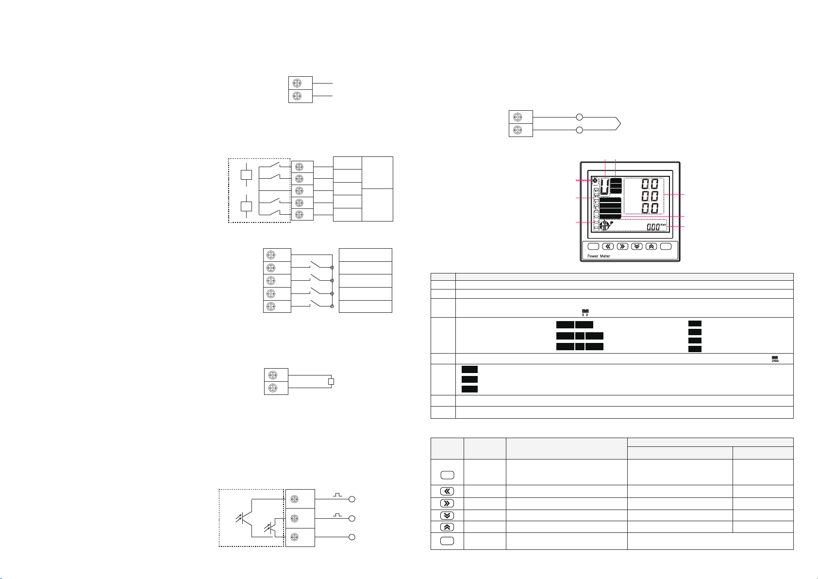
The instrument has a universal (AC/DC) power input interface. If no special explanation is given, it is a standard product
of AC220V power interface. The limit working voltage of the instrument is AC 85-265V. Please ensure that the supplied
power is suitable for this series. Products to prevent damage to the product.Also recommended:
1. It is recommended to use AC power to install 1A fuseon the side of the line of fire;
2.For areas with poor network quality, it is suggested that a surge suppressor
be installed in the power circuit to prevent lightning strikes and a fast pulse
train suppressor be installed.
7
3.7 Power Supply
3.11 Energy Pulse Output
The instrument has a switch input detection function and adopts the dry node
signal input method. The instrument is equipped with a +24V working power
supply inside, and no external power supply is required. When it is connected
externally, it is collected by the instrument switch input module DI, and the
interface shows that it is in the open state. When it is disconnected externally,
it will be disconnected through the digital input module DI of the instrument
collector, and the interface will be in the open state.
Switch input commom
point
Switch input1
Switch input2
Switch input3
Switch input4
COM
S1
S2
S3
S4
12
13
14
15
16
3.9 Switch Input
L(+) AC:85~265V
working
power DC:100~240V
N(-)
1
2
This meter with relay output function can be used for alarm indication and protection control output function in various
occasions. When the digital output is valid, the relay output is on, and when the digital output is off, the relay output is off.
1.High Alarm : When the high alarm indicates that the alarm
threshold is higher than the alarm item,the relay switch output
turns on.
2.Low Alarm : When the low alarm indicates that the alarm threshold
is lower than the alarm item, the relay switch output turns on;
3.Remote control relay : If the relay output control is selected as
the remote control mode, the output of the relay is set to
“remote control” through the programming operation, and the
output of the relay can be controlled through communication.
3.8 Relay output
Meter
Inside
3
4
5
6
7
NO Opened
NC Closed
1st loop alarm
2nd loop alarm
ACOM Alarm Commom
Point
NO Opened
NC Closed
Energy metering and pulse output: the meter provides positive and negative active energy metering, 2 loops energy pulse
output functions and RS485 digital interface to complete the display and remote transmission of energy data. The energy
pulse (resistance signal) of the photocoupler relay with open-collector level is used to realize the remote transmission of active
energy (forward) and reactive energy (forward), and the remote computer terminal, PLC and DI switch acquisition module is
used to collect the instrument. The total number of pulses to achieve energy cumulative measurement. Use the pulse output
method to check the accuracy of the electrical energy (national measurement procedures: comparison method of pulse error
of the standard form)
1.Electrical characteristics: VCC<=48V IZ<=50mA
in the circuit diagram of the pulse acquisition interface
2.Pulse constant: 9000 imp/kWh(kvarh), the fastest pulse
speed does not exceed 200mS. Its significance is: when
the meter accumulates 1kWh (1kvarh) output pulse
number is 9000.
7
Meter
Inside
17
RP
reactive energy
pulse output
active energy
pulse output
pulse commom point
AP
PCOM
18
19
The device has a two-wire RS-485 communication port with terminals labeled A+, B-. High-speed optocoupler isolation and
protection circuits prevent common-mode and differential-mode voltage interference, lightning strikes, and miswiring from
damaging the communications port. The RS-485 communication mode allows a maximum of 32 instruments to be connected
on one bus. In this case, an RS-232C/RS-485 converter is required. The communication cable can be an ordinary shielded
twisted pair cable. The total length cannot exceed 1200 meters. The positive and negative polarity of the RS-485 port of each
device must be connected correctly, and one end of the cable shield is grounded. If the shielded twisted pair is long, it is
suggested to connect a 120Ω resistor at the end to improve the reliability of communication.
8
4.2 Display Area Description
3.12 Communication Output
IV. OPERATION INSTRUCTIONS
4.1 Panel diagram
4.3 Key Description Form
Power Meter
S E T E SC
3
4
DO1
DO2
DO3
P
DO4
v
v
v
B
A
C
COM1
This Sharp
Peak
Flat
THD
Unbl
MAX
Last
I II
Valley
Month
1
7
4
8
62
3
5
No.
1
2
3
4
5
6
7
8
Display Description
Communication indicator: The indicator will keep blinking while it is passing
Switch input indicator, when a certain amount of switch is closed, the corresponding switch display frame will be filled with solid. If the second
way switch is turned on, the display state is as follows:
Alarm or remote output indicator: When an alarm occurs, the corresponding output indicator will be filled with solid. Such as:
Display the current display category of the data display area: like the voltage corresponds to "U", the current corresponds to "A", etc.
Measurement data real-time display area, can display the voltage, current, power etc
Indicating the corresponding rate
of multi-rate:
Power display area: Measurement range is 0~999999.99, Exceeding the maximum will automatically flip
THD
Unbl
MAX
Indicate total harmonic content
Indication imbalance
Indicates the maximum
S 2
DO2
This
Last I
II
Month
Month
Month
Last
indicate this month
indicate last month
indicate last two months
Sharp
Peak
Flat
Valley
indicate“sharp”
indicate“peak”
indicate“flat”
indicate“valley”
Please use shielded twisted pair connection
10
11
B-
A+ RS485
8
8
Key symbol Key Name
Confirm Key
Left shift key
Right shift key
Reduce key
Increase key
Return key
1. short press to switch display categories:
instantaneous electrical parameters→ voltage
harmonic→current harmonic→ Multi-rate electricity
2. long press to enter setup menu
backward turning in the display class
forward turning in the display class
lower power display switch back
lower power display forward switch
short press for the lower power display column and
return to integrated active power display
enter the next menu
visit last parameter
visit next parameter
enter the parameter modification status
enter the parameter modification status
confirm the changes
cursor left
cursor right
decrease of value
increase of value
exit the last operation until you exit the setup menu
Measurement Mode
Setting Mode
Parameter selection status
SET
E SC
Parameter modification
status
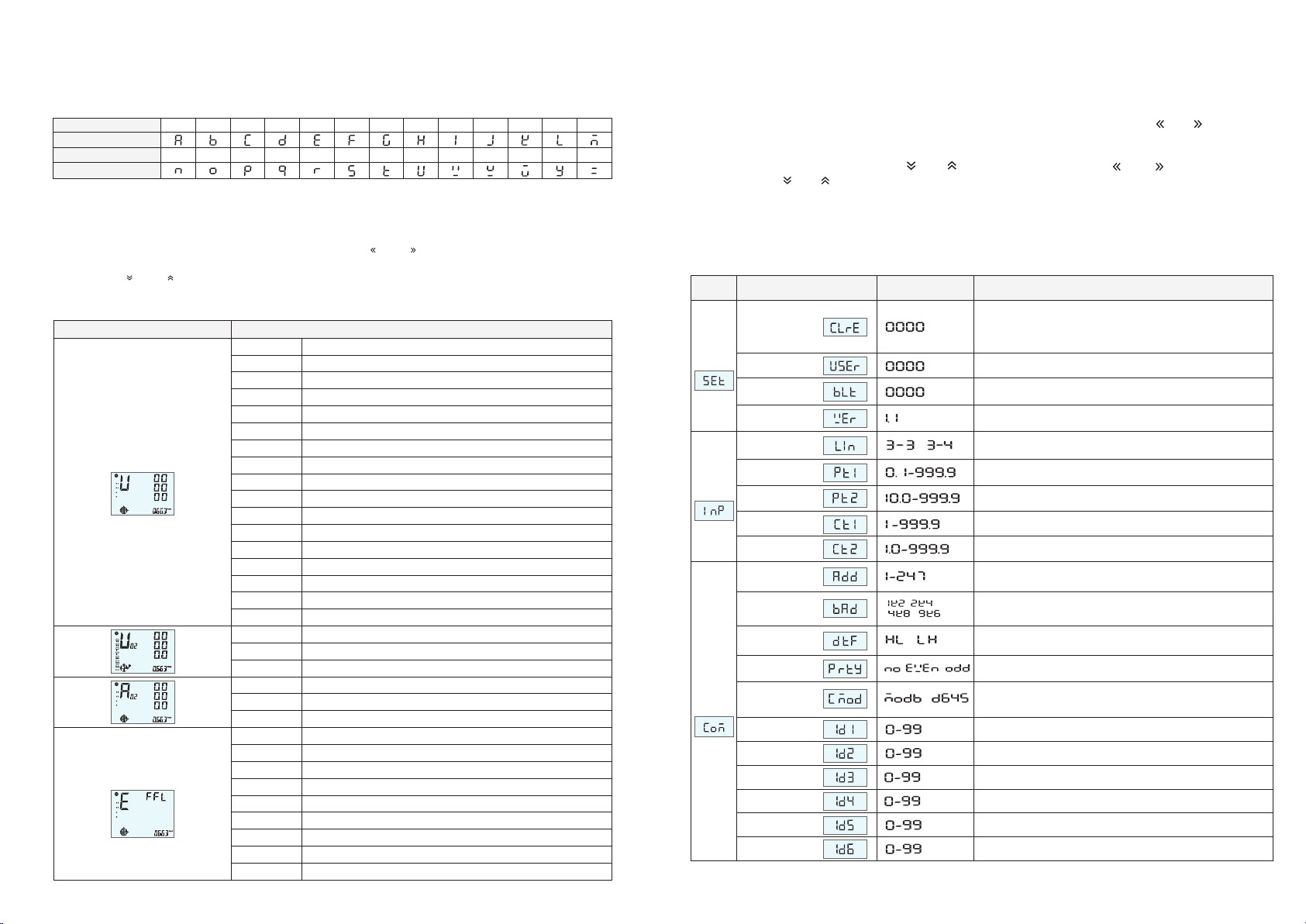
Because this instrument uses a pen-type liquid crystal, it may not be intuitive when displaying characters. Therefore, when
reading ambiguity occurs, please check according to the following form. The characters that appear in the instrument have
been mapped to the following form.
9
4.4 26 English letters display method on LED:
English letter
Display method
English letter
Display method
A
N
B
O
C
P
D
Q
F
S
G
T
J
W
K
X
L
Y
M
Z
H
U
I
V
E
R
4.5 Measurement display page description
Display category Display content
Screen 1 3 phase voltage(press“ESC” key to display 3 phase wire voltage)
3 phase current
system frequency
Voltage imbalance
maximum voltage
total harmonic content of voltage
total harmonic content of current
3 phase voltage 2nd harmonic content
3 phase voltage 31th harmonic content
0 phase current
Current imbalance
maximum current
3 phase current 2nd harmonic content
3 phase current 31th harmonic content
3 phase active power
3 phase reactive power
3 phase apparent power
3 phase power factor
Combined power and power factor
Maximum demand
Current demand
Screen 2
Screen 3
Screen 6
Screen 4
Screen 5
Screen 7
Screen 8
Screen 9
Screen 12
Screen 10
Screen 11
Screen 13
Screen 14
Screen 17
Screen 15
Screen 16
Voltage
Harmonics
Current
Harmonics
…
…
Screen 1
Screen 30
…
…
Screen 1
Screen 30
date
time
monthly sharp energy
monthly peak energy
monthly flat energy
monthly valley energy
valley energy last two month
flat energy last two month
…
…
Screen 1
Screen 2
Screen 3
Screen 4
Screen 5
Screen 6
Screen 13
Screen 14
Instantaneous electrical parameters
3
4
DO1
DO2
DO3
P
v
v
v
B
A
C
COM1
3
4
DO1
DO2
DO3
P
%
COM1
3
4
DO1
DO2
DO3
P
%
COM1
Multi-rate electricity
3
4
DO1
DO2
DO3
P
DO4
COM1
1. Press "SET" key to switch display categories, namely, instantaneous electrical parameters → voltage subharmonic →
current subharmonic → complex rate → instantaneous electrical parameters;
2.In a certain display class, the display is displayed by pressing the " " and " " keys;
3.In the instantaneous electrical parameters, voltage sub-harmonics, and current sub-harmonics,the energy can be viewed
through the “ ” and “ ” keys, which are:integrated active energy → positive active energy → negative active energy →
integrated reactive energy → positive reactive energy → negative reactive energy → first quadrant reactive energy →
second quadranteactive energy → third quadrant reactive energy →fourth quadrant reactive energy
10
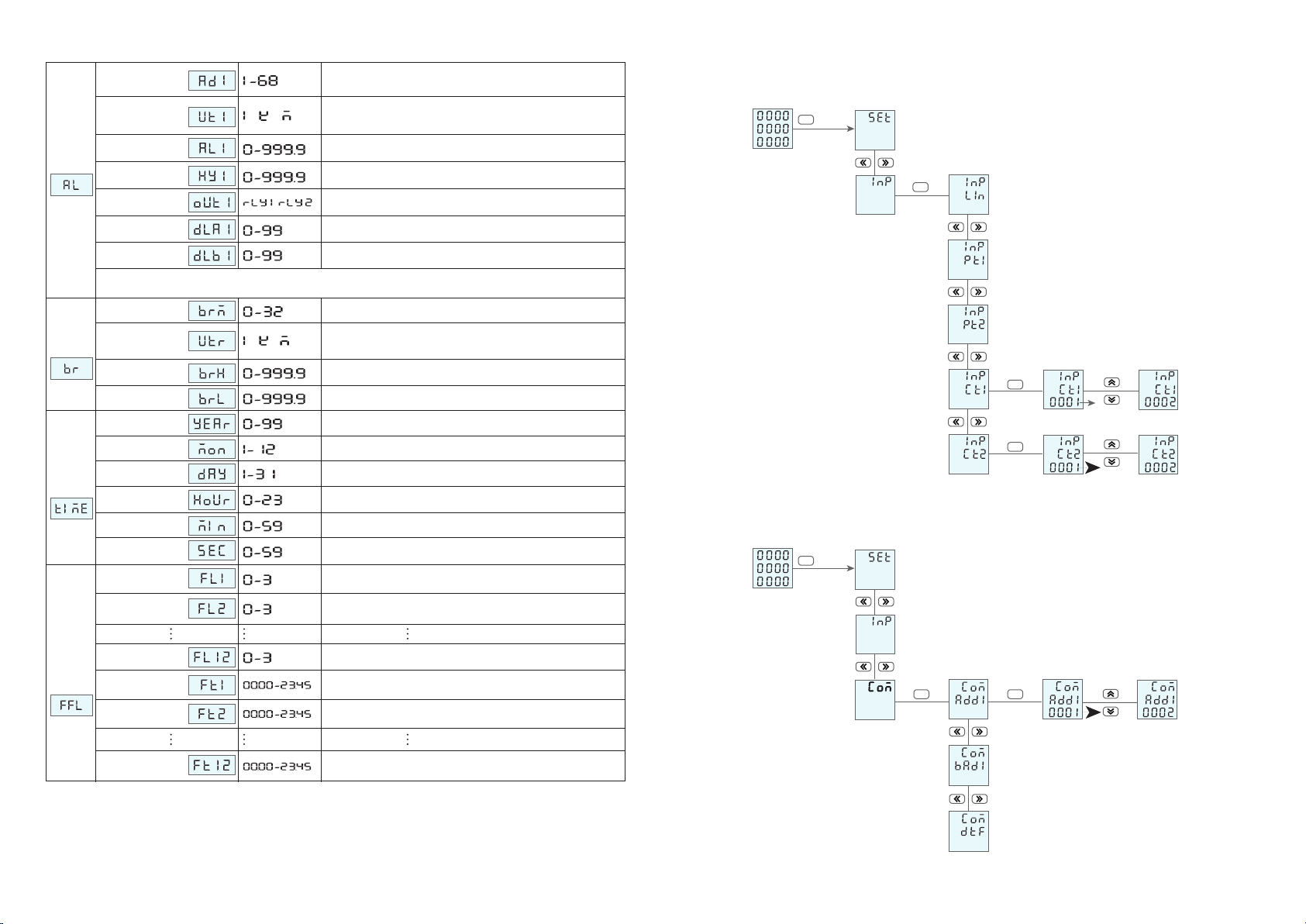
4.6 Menu Operation Illustration
Menu Structure and Function Description
Under user menu status
1.Press “ SET ” key more than 3 second, if the user password is set, it will pop up the password input box,input the correct
password to enter the user’ menu to modify the patameter.
2.If the current display is the first class, press confirm key “ SET ”, to enter next class display, click “ ”、“ ”key to
change the menu item
3.If the current display is second or third class , press “ ESC ” key to return to previous class display
4.If the current display is third class,press “ ”、“ ” key to flash digit, press key “ ”、“ ” to shift place
Keep pressing “ ”、“ ”
to change value; press confirm key “ SET ” to keep the value; If press the “ ESC ” key, it does not save the set value and
return to second class.
5.After modifying the parameters, press “ ESC ”,to exit user menu, return to measuring status.
Input “1111”to clear energy;Input “2222”to clear maximum demand;
Input “3333” to clear event;
Input“4444”to clear the maximum of voltage, current;
input “1234” to reset to factory setting
Setting user password
Clear Energy
System
Setting
Select the input network of the measured signal
Primary coil voltage , unit kV
Network
Volt transform
User password
Signal
Input
Backlight delay time , unit is second . If set as 0 , mean keep on
lighting all the time.
Software version
Backlight time
Software version
1st Level 2nd Level 3rd Level Description
Secondary coil voltage , unit V
Primary coil current , unit A
Secondary coil current ,unit A
Current transform
Volt transform
Meter Address Range
Baud Rate:1k2 means 1200, 2k4 means 2400, 4k8means 4800,
9k6 means 9600, 19k means19200
Address
Baud Rate /
/ /
/
/
Data sequence: high word first or low word firstData order
Comm.
Parameter
Checking Bit
ADD 1
ADD 2
Protocol Selection
ADD 4
ADD 5
No check/even check/odd check
RS5485 address 1, two decimal number display
RS5485 address 4, two decimal number display
RS5485 address 5, two decimal number display
RS5485 address 6, two decimal number display
RS5485 address 2, two decimal number display
MODB: select MODBUS-RTU protocol
D645:select DLT645 protocol
ADD 3 RS5485 address 3, two decimal number display
/ /
/
ADD 6
Current transform
11
Continued from the front chart
Alarm mode
Alarm Action
Value
Alarm hysteresis
value
Alarm Unit
Alarm start
delay
Alarm finish
delay
When character “ do ” is remote control mode, otherwise it is
alarm mode reference "4.9 alarm, transmission parameter
comparison chart"
1st alarm value setting, consistent with the basic display unit
alarm start delay time , unit : second
alarm finish delay time , unit : second
1st alarm hysteresis value setting, consistent with the basic
display unit
1: means international standard unit, K: means 1000 times of
international standard unit, M: means1000000 times of
international standard unit.
Alarm relay
setting 1st alarm relay output setting
/ /
/
Switch
Settings
2nd loop alarm parameter setting way refers to the 1st loop alarm
Period 12 rates, 0,1,2,3 stands sharp, peak, flat, valley
Period 1 Start Time
Period 2 Start Time
Period 12 Start Time
Period 12 rates
Period 1
Start time
Period 2
Start time
Period 12
Start time
Multi-rate
setting
Minute
Second
Minute
Second
Period 1 rates, 0,1,2,3 stands sharp, peak, flat, valley
Period 2 rates, 0,1,2,3 stands sharp, peak, flat, valley
Period 1 rates
Period 2 rates
Time
setting
Year
Month
Day
Hour
Year
Month
Day
Hour
Transmit high
limit
Transmit low
limit
Analog
output
Transmit output 20mA
Transmit output 4mA
Transmit mode
selection Refer to “4.9 alarm, transimission parameter comparison chart”
Transmit unit 1: means international standard unit, K: means 1000 times of
international standard unit, M: means1000000 times of
international standard unit.
/ /
12
4.7 Menu modification example
2. Setting the communication address method
Primary
current
setting
( Unit:A )
Secondary
current
setting
( Unit:A )
1st level
2nd level
3rd level Modified state
Measure state
System setting
sin
>5s
SET
SET
SET
SET
1. Setting the current ratio method
Instrument
address
setting
Communication setting
Modified state
>5s
SET
SETSET
1st level
3rd setting
Measure state
System setting
Signal setting
2nd setting

14
4.9 Alarm output and transmission output parameter
Parameter
Ua(A phase voltage)
Ub(B phase voltage)
EP(total active power)
EQ(total reactive power)
unbalance
unbalance
F frequency
0 wire current
PFc(C phase power factor)
PF(total power factor)
Uc(C phase voltage)
U( phase voltage of A, B or C)
I(phase current of A、B、C)
UL(wire voltage of AB、BC、CA )
Uab(AB wire voltage)
Ubc(BC wire voltage)
Uca(CA wire voltage)
Ia(A wire current)
Ib(B wire current)
Ic(C wire current)
Pa(A phase active power)
Pb(B phase active power)
Pc(C phase active power)
P(total active power)
Qa(A phase reactive power)
PFb(B phase power factor)
Qb(B phase reactive power)
Qc(C phase reactive power)
Q(total reactive power)
Sa(A phase apparent power)
Sb(B phase apparent power)
Sc(C phase apparent power)
S( total apparent power)
PFa(A phase power factor)
Switch output
(low alarm) code
1
3
57
59
61
63
65
67
53
55
5
7
9
11
13
15
17
19
21
23
25
27
29
31
33
51
35
37
39
41
43
45
47
49
(FL)
(EPL)
(EQL)
(InL)
(UNNB)
(INNB)
(UaL)
(UbL)
(PFcL)
(PFL)
(UbcL)
(UcaL)
(ULL)
(IaL)
(IbL)
(IcL)
(IL)
(PaL)
(PbL)
(PcL)
(PL)
(QaL)
(QbL)
(QcL)
(QL)
(SaL)
(SbL)
(ScL)
(SL)
(PFaL)
(PFbL)
(UcL)
(UL)
(UabL)
Switch output
(high alarm) code
2
4
58
60
62
64
66
68
54
56
12
14
16
18
20
22
24
26
28
30
32
34
6
8
10
52
36
38
40
42
44
46
48
50
(FH)
(EPH)
(EQH)
(InH)
(ULNB)
(PNNB)
(UaH)
(UbH)
(PFcH)
(PFH)
(UbcH)
(UcaH)
(ULH)
(IaH)
(IbH)
(IcH)
(IH)
(PaH)
(PbH)
(PcH)
(PH)
(QaH)
(QbH)
(QcH)
(QH)
(SaH)
(SbH)
(ScH)
(SH)
(PFaH)
(PFbH)
(UcH)
(UH)
(UabH)
Transmission output(4-20mA)code
1
2
30
31
29
32
0
27
28
11
12
13
14
15
16
17
3
4
5
6
7
8
9
10
26
18
19
20
21
22
23
24
25
(F)
(EP)
(EQ)
(In)
(no)
(Ua)
(Ub)
(PFc)
(PFs)
(Qb)
(Qc)
(Qs)
(Sa)
(Sb)
(Sc)
(Ss)
(PFa)
(PFb)
(Ubc)
(Uca)
(no)
(Ia)
(Ib)
(Ic)
(no)
(Pa)
(Pb)
(Pc)
(Ps)
(Qa)
(Uc)
(no)
(Uab)
13
The meter settings are as follows
4.8 Multi-rate setting instructions
Multiple rate schedule correspondence form
hour
0 0 0
0
0
0
1
1
1
1
2
2
2
2
3
3
3
3
15
30
45
0
15
30
45
0
15
30
45
0
15
30
45
1
2
3
4
5
6
7
8
9
10
11
12
13
14
15
minute period hour
4 0 16
4
4
4
5
5
5
5
6
6
6
6
7
7
7
7
15
30
45
0
15
30
45
0
15
30
45
0
15
30
45
17
18
19
20
21
22
23
24
25
26
27
28
29
30
31
minute period hour
8
032
8
8
8
9
9
9
9
10
10
10
10
11
11
11
11
15
30
45
0
15
30
45
0
15
30
45
0
15
30
45
33
34
35
36
37
38
39
40
41
42
43
44
45
46
47
minute period hour
12 0 48
12
12
12
13
13
13
13
14
14
14
14
15
15
15
15
15
30
45
0
15
30
45
0
15
30
45
0
15
30
45
49
50
51
52
53
54
55
56
57
58
59
60
61
62
63
minute period hour
16 0 64
16
16
6
17
17
17
17
18
18
18
18
19
19
19
19
15
30
45
0
15
30
45
0
15
30
45
0
15
30
45
65
66
67
68
69
70
71
72
73
74
75
76
77
78
79
minute period hour
20 0 80
20
20
20
21
21
21
21
22
22
22
22
23
23
23
23
15
30
45
0
15
30
45
0
15
30
45
0
15
30
45
81
82
83
84
85
86
87
88
89
90
91
92
93
94
95
minute period
1.The 0, 1, 2, and 3 in the rate menu correspond to Sharp, Peak, Flat, and Valley rates, respectively. Customers can
choose to use Two or more of these rates;
2.The rate corresponds to the start time of the rate in that period. Similarly, customers can use only 2 or more of
these hours.
For example:The sharp, peak, flat, valley time set as follows
Peak hours:09:00-11:30、14:00-16:30、19:00-21:00(total 7 hours);
Flat hours:07:00-09:00、11:30-14:00、16:30-19:00、21:00-23:00(total 9 hours);
Valley hours:23:00- next time 07:00(total 8 hours)
Note: For correspondence, the corresponding multi-rate period is divided into 96 segments by 15 minutes per day
for 24 hours a day, from 0-95,0 to 00:00 for a 24-hour system, and 95 to 24:45 for a 24-hour system,
corresponding to the time It is the start time of the rate energy during this period.
Rate menu Setting value Remark Setting value Remark
Corresponding
communication value
(note)
FL1 2 07.00 07:00Flat 28FT1
1 09.00 09:00FL2 Peak 36FT2
2 11.30 11:30FL3 Flat 46FT3
1 14.00 14:00FL4 Peak 56FT4
2 16.30 16:30FL5 Flat 66FT5
1 19.00 19:00FL6 Peak 76FT6
2 21.00 21:00FL7 Flat 84FT7
3 23.00 23:00FL8 Valley 92FT8
3 23.00 23:00FL9 Valley 92FT9
3 23.00 23:00FL10 Valley 92FT10
3 23.00 23:00FL11 Valley 92FT11
3 23.00 23:00FL12 Valley 92FT12
Time menu

16
7.1 MODBUS-RTU protocol
VII. Communication Protocol Description
7.2 Communication frame format description
The following chart shows the meaning of exception error codes:
7.1.5 Communication frame delay
7.1.2 Data Format
Data Bit Checking Bit Stop Bit
1 8 None, Even, Odd checking(Programmable) 1
Start Bit
Hosting Sending
Slave address
Function Code
Start Add
Data Length
CRC Code
Bytes
1
1
2
2
2
Information Send
01
03
0x4000
0x0002
0xD1CB
Remark
Send to slave at address 01
Read register
Start Add
Read 2 registers (4 bytes in total)
The host calculates the CRC code
Error code Name Description
0X01
0X02
0X03
0X04
Function code error
Variable address error
The limit of the data value
Incorrect or out of frame length
The meter received an unsupported function number
The data value sent by the host exceeds the data range corresponding to the instrument or the data
structure is incomplete
The function code and the communication frame length are inconsistent or request exceeds the limit
The host specified data location is over the range of the meter or an illegal register operation has been
received
7.1.1 MODBUS-RTU communication protocol,adopts RS485 half-duplex communication to check 16-bit CRC.The meter does not return
the check error.
1.All RS485 loop communication should follow master and slave mode.In this way, information and data are transferred between a single
master station and up to 32
2.The master station will initialize and control all the information transmitted on the RS485 communication loop ( daisy chain );
3.In any case, communication cannot be started from a slave station
4.Communication on all RS485 loops takes place in a "packaged" manner. A data packet is a communication frame.A packet can
contain up to 128 bytes.
5.The master station sends called request and the slave sends called response.;
6.In any case, the slave can only respond to one request from the master station;
7.1.4 Communication exception handling
If the master sends an illegal packet or if the master requests an invalid data register, an abnormal data response will be generated. This
abnormal data response consists of the slave address, function code, fault code, and check field. When the high-order bit position of the
function code domain is 1, it indicates that the data frame at this time is an abnormal response.
According to MODBUS communication requirements, abnormal response function code = request function code + 0x80; when abnormal
response occurs, the highest position of function number is 1. For example, if the host request function number is 0x04, the function
number returned from the slave corresponds to 0x84.
7.2.1 Function Code“03”:Read multiple register input
Eg:The host reads the UA (A phase voltage), and it is measured that the A phase voltage is 220.0V. The UA's address code is 0x4000
because UA is a fixed-point number (4 bytes) and occupies 2 data registers. The corresponding hexadecimal data of 220.0V is:
0x0000898 (200)
Host sent message format: (default high word first)
There should be an appropriate delay between the requests from the master station for the two frames. When the baud rate is 9600.
In order to ensure a correct response, it is recommended that a 300mS delay be reserved between the two frames. When the baud rate
decreases, the communication delay should increase appropriately.
7.1.3 Communication frame format
Frame Content Bytes Instructions
Slave Station Add 1
1
2
Valid slave address range is 1-247
The length of data that needs to be read or written
The location where the data area is stored when the slave executes a valid command. Different variables occupy
different number of registers, some address variables occupy two registers, 4 bytes of data, some variables occupy
a register,2 bytes of data, please use according to the actual situation
Function Code
Data Add
2Data length
Slave station returns data or master data to be writtenVariableData
The MODBUS-RTU mode uses 16-bit CRC. The sending device shall calculate CRC16 on each data in the parcel, and the
final result shall be stored in the test domain. The receiving device shall also calculate CRC16 on each data (other than
the check field) in the parcel and compare the result field check fields. Only the same package can be accepted.
2CRC Check Code
Read one or more current register values
Writes the specified value to an internal register
0X03
0X06
0X10 Writes the specified value to multiple internal registers
15
VI.EVENT RECORD DESCRIPTION
Event recording is currently an optional feature and can only be read through communications. The specific instructions are
as follows:
Eg, To read the latest first record,
the data is as follows:
“01 03 45 00 00 07 13 EC”
Answers are as follows:
“01 03 0E 00 01 00 0E 00 09 00 12 00 11 00 07 00 21 0C F7”
Indicates that the event is a modified parameter. The moment of occurrence is
014-9-18 17:07:33
6.3 Reading of event records
ADD
XX
Order
03
Data ADD
45 XX
Data length
00 07
CRC
XX XX
No. Correspondence data
1 1 Power on the meter
Event Desciption
2 2 modified parameter
3 3 Clear Energy
4 4 Clear Demand
5 5 Clear Event
6 6 Clear maximum
7 7 1st alarm action
8 8 1st alarm end
9 9 2nd alarm action
10 10 2nd alarm end
V. SIMPLE TROUBLESHOOTING
Power failed to join the device
Incorrect voltage measurement
Incorrect current measurement
Incorrect power measurement
Switching voltage
No control command received
Incorrect relay operation mode
The measurement value
is incorrect or does not
meet expectations
Switch status does
not change
Relay does not operate
The upper end cannot
communicate with the
device
Device communication address is incorrect
Device communication rate is incorrect
Communication link is not connected to
terminating resistor
Communication link is disturbed
Communication line interruption
Check whether the correct operating voltage is added to the L/+ and N/- terminals of the device
Check if control power fuse is burned
Check if the neutral connection is reliable
Check whether the measured voltage matches the rated parameter of the equipment
Check if the PT ratio parameter setting is correct
Check whether the measured current matches the rated parameter of the device
Check CT ratio parameter setting is correct
Check the measurement mode setting is correct
Check the voltage and current phase sequence is correct
Check the current name is wrong
Check whether the external node type matches the device's rated parameters
Check the external wiring is correct
Check the communication link is correct
Check current relay is in correct mode
Check whether the device address is consistent with the definition
Check whether the device communication rate is consistent with the definition
Check whether the 120 ohm resistor is added
Check that the communication shield is well grounded
Check the communication cable is disconnected
Reason Solution
Problem
No display after adding
control power
6.2 Event Record Format
Event Type
1-10 Year Month Day Hour Minute Second
Event Occurred Time
A total of 32 groups of events were included, both of which included event types and times. The event record uses a
sequential recording method: the first record is always the most latest event and extends back to a total of 32 records.
6.1 Event Types
Including the followed 10 types:

18
7.2.4 CRC code calculation method
Attched:CRC calculation C language source code
unsigned int GET_CRC(unsigned char * buf,unsigned charnum)
{
unsigned chari,j;
unsigned int WCRC = 0xffff;
for(i=0;i<num;i++)
{
WCRC ^= (unsigned int)(buf[i]); // Cyclic redundancy check
for(j=0;j<8;j++)
{
if(WCRC&1)
{
WCRC >>= 1;
WCRC ^= 0XA001;
}
else
WCRC >>= 1;
}
}
return(WCRC); // Get CRC check code
}
7.3 Power meter communication address mapping
1.Preset a 16-bit register to hexadecimal FFFF (that is all 1); call this register CRC register;
2.Compare the first 8-bit binary data (the first byte of the communication message frame) with the lower 8 bits
of the 16-bit CRC register and place the result in the CRC register.
3.Move the contents of the CRC register one bit to the right (towards the lower bit) to fill in the highest bit with
0 and check the shifted-out bit after the right shift;
4.If the shift-out bit is 0: repeat step 3 (right shift one bit again); if the shift-out bit is 1: CRC register and
polynomial A001
(1010 0000 0000 0001) XOR;
5.Repeat steps 3 and 4 until right shift 8 times so that the entire 8-bit data is all processed;
6.Repeat Step 2 to Step 5 to process the next byte of the communication message frame.
7.After all the bytes of the communication information frame are calculated according to the above steps, the
high and low bytes of the obtained 16-bit CRC register are exchanged;
8.The final CRC register content is: CRC code.
Instantaneous electrical parameter communication address
0x4004 Phase voltage C
0x4006 Wire voltage AB
0x4008 Wire voltage BC
0x400a Wire voltage CA
0.1V
0x4000 Phase voltage A
0x4002 Phase voltage B
0x400c Phase current A
0x400e Phase current B
0x4010 Phase current C
0x4012 Active power A
0.001A
0x4020 Total reactive power
Apparent power A
0x4022
Power factor A
0x4024
Power factor B
0x4026
Power factor C
Apparent power B
Apparent power C
Total apparent power
0x4028
0x402a
0x402c
0x402e
0.1VA
0.001
0x4014 Active power B
0x4016 Active power C
0x4018 Total active power
0x401a Reactive power A
0x401c Reactive power B
0x401e Reactive power C
0.1W
0.1var
0x4034 Active power
3
4
5
6
1
2
7
8
9
10
17
18
19
20
21
22
23
24
11
12
13
14
15
16
27
26
25
0x4032
0x4030
2
2
2
2
2
2
2
2
2
2
2
2
2
2
2
2
2
2
2
2
2
2
2
2
2
2
2
long
long
long
long
long
long
long
long
long
long
long
long
long
long
long
long
long
long
long
long
long
long
long
long
long
long
long
R
R
R
R
R
R
R
R
R
R
R
R
R
R
R
R
R
R
R
R
R
R
R
R
R
R
RTotal power factor
Frequency 0.01Hz
0.001kWh
17
The format of the message returned from the slave response correctly
Return message format from slave response:
Slave response
Slave address
Function code
Reading
Register data
CRC code
Bytes
1
1
1
1
1
1
1
2
Returned information
01
03
04
0x00
0x00
0x08
0x98
0xFC59
Remark
From slave 01
Read register
2 registers total 4 bytes
High byte of contents at address 0x4000 memory
High byte of contents at address 0x4000 memory
Low byte of contents at address 0x4000 memory
The CRC code calculated by the host
Low byte of contents at address 0x4000 memory
Return message format from slave response:
Host sending
Slave address
Function code
Initial address
Write data
CRC code
Bytes
1
1
1
1
1
1
2
Send Message
01
06
0x49
0x00
0x00
0x0B
0xDE51
Example
Sending to slave 01
Writing multiple register
High byte of data
Low byte of data
The CRC code calculated by the host
The low byte of the starting adrress of the register to be written
The high byte of the starting adrress of the register to be written
Host sending
Slave address
Function code
Initial address
Write data
CRC code
Bytes
1
1
1
1
1
1
2
Send Message
01
06
0x49
0x00
0x00
0x0B
0xDE51
Example
Sending to slave 01
Writing single register
High byte of data
Low byte of data
The CRC code calculated by the host
The high byte of the adrress of the register to be written
The low byte of the adrress of the register to be written
7.2.2 function code “06”:wrinting ingle register
Packet format sent by the host:
eg:Host writes fixed-point number 1st alarm mode AD1. Assume that the address code of AD1 is 0x4900 because AD1 is a
fixed-point number and occupies 1 data register, and decimal 11 corresponds to 0x000B.
Host sending
Slave address
Function code
Initial address
Data word length
to be written
To write data bytes long
Write data
CRC Code
Bytes
1
1
1
1
1
1
1
1
1
2
Send Message
01
10
0x49
0x00
0x01
0x00
0x02
0x00
0x0B
0x3F53
Example
Sending to slave 01
Writing multiple register
The high byte of the starting adrress of the register to be written
The low byte of the starting adrress of the register to be written
The word length of the write data is low byte
The word length of the write data is high byte
The byte length of data (1 byte in total)
High byte of data
Low byte of data
The CRC code calculated by the host
7.2.3 function code “10”:write multiple register
Packet format sent by the host:
eg:Host writes fixed-point number 1st alarm mode AD1. Assume that the address code of AD1 is 0x4900 because AD1 is
a fixed-point number and occupies 1 data register, and decimal 11 corresponds to 0x000B.
Slave address
Function code
Initial address
Save data word length
CRC Code
1
1
2
2
2
01
10
0x4900
0x0002
0x1795
From slave 01
Writing multiple register
Starting address is 0000
Save 2 words of data
The CRC code calculated by the host
Slave response Bytes Send Message Example

20
0x4200 1 Int 0.01%
0.01%
0.01%
A phase voltage 0th harmonic
Fractional harmonic communication address
A phase current 0th harmonic0x4220 1 Int2
1
0x4300 1 Int
Reserved Expansion
Reserved Expansion
0x4320 1 Int2
1
2
1 0x4400 1 Int
0x4420 1 Int
0x4505
0x4506
1
1 short
short
1
2
3
4
5
6
7
0x4500
0x4501
0x4502
0x4503
0x4504
1
1
1
1
1
short
short
short
short
Minute
Second
Year
Month
Day
Hour
Latest event type
Event record communication address
the latest event occurred time short
0x45de
0x45df
1
1 short
short
8
9
10
11
12
13
14
0x45d9
0x45da
0x45db
0x45dc
0x45dd
1
1
1
1
1
short
short
short
short
Minute
Second
Day
Hour
32nd event type
...... (30 events in the middle)
32nd event occurred time short
0x4805
0x4806
0x4807
1
1
1
int
int
Communication Address 1
Baud Rate 1(attached 2)
Data Format 1
0x4818 1 intCommunication Address 2
Baud Rate 2(attached 2)0x4819 1 int No decimal point
0.1
0.1
int
10
1
2
3
4
5
6
8
9
7
0x4800
0x4801
0x4802
0x4803
0x4804
1
1
1
1
1
int
int
int
int
0.1
0.1
0.1
Wiring Method(1)
System Parameter Communication Adress
Alarm parameter communication address
Voltage transformation ratioPT1
Voltage transformation ratio PT2
Current transformation ratioCT1
Current transformation ratio CT2 int
0x4900
0x4901
0x4902
1
1
1
int
int
1st Alarm Mode
1st Alarm Unit(attached 3)
1st Alarm Value
0x4903 1 int1st Alarm Backlash
1st Alarm Output Mode( attached 7)0x4904 1 int
int
5
11
12
13
14
1
3
4
2
0x4905 1 int1st Action Delay
1st Removal Delay0x4906 1 int7
6No decimal point
0x480a
0x480b
0x480c
0x480d
1
1
1
1
int
int
int
int
Data Format 2
Switch Output(attached 4)
Switch Input(attac5)
Remote Control Input(attached 6)
15 0x480f 1 int
R
R
R
R
R
R
R
R
R
R
R
R
R
R
R
R
R
R
R
R
R/W
R
R/W
R/W
R
R/W
R/W
R/W
R/W
R/W
R/W
R/W
R/W
R/W
R/W
R/W
R/W
R/W
R
R
R/W
R/WBacklight time
B phase voltage 0th harmonic
B phase current 0th harmonic
C phase current 0th harmonic
C phase current 0th harmonic
Year
Month
19
Cumulative total active energy last month
Cumulative total sharp active energy last month
Cumulative total peak active energy last month
Cumulative total flat active energy last month
Cumulative total valley active energy last month
Cumulative total active energy last two months
0x410a
0x410c
0x410e
0x4110
0x4112
0x4100
0x4102
0x4104
0x4106
0x4108
0x411e
0x4120
0x4122
0x4124
0x4126
0x4114
0x4116
0x4118
0x411a
0x411c
0x4060
0x4062
0x4064
0x4066
0x4068
0x406a
0x406c
0x406e
0x4048
0x404a
0x404c
0x4052
0x4054
0x4056
0x4058
0x405a
0x405c
0x405e
0x4070
0x4072
0x4074
0x4076
0x4036
0x4038
0x403a
0x403c
0x403e
0x4046
10
1
2
3
4
5
6
8
9
7
20
11
12
13
14
15
16
18
19
17
34
35
36
39
40
41
42
37
38
43
44
45
46
47
48
49
50
51
52
53
54
55
28
29
30
31
32
33
long R
long R 0.1V
0.001A
0.1%
0.001kvarh
long R
long R
long R
long R
long R
long R
long
long
long
long
long
long
long
long
long
long
R
R
R
R
R
R
R
R
R
R
0.1kvar
0.001A
0.1W
1°
long R
long R
long R
long R
0.1%
2
2
2
long
long
R
R
R
2 long R
2 long R
0.001kWh
long
2
2
2
2
2
long
long
long
long
R
R
R
R
R
long
2
2
2
long
long
R
R
R
2 long R
2 long R
long
2
2
2
2
2
long
long
long
long
R
R
R
R
R
long
long R
long R
long R
long R
2
2
2
2
2
2
2
2
2
2
2
2
2
2
2
2
2
2
2
2
2
2
2
2
2
2
2
2
long
long
R
R
0.001kvarh
0.001kWh
0.001kvarh
Total cumulative total active energy
Multi-rate energy communication address
Total cumulative sharp active energy
Total cumulative peak active energy
Total cumulative valley active energy
Total cumulative flat active energy
Cumulative total active energy this month
Cumulative total sharp active energy this month
Cumulative total peak actenergy this month
Cumulative total flat actenergy this month
Cumulative total valley actenergy this month
Cumulative total sharp active energy last two months
Cumulative total peak active energy last two months
Cumulative total flat active energy last two months
Cumulative total valley active energy last two months
Phase voltage maximum
Wires voltage maximum
Current maximum
Voltage imbalance
Current imbalance
A, B phase voltage angle
B, C phase voltage angle
C, A phase voltage angle
Maximum active power demand
Current reactive power demand
Maximum reactive power demand
A phase voltage total harmonic content
B phase voltage total harmonic content
C phase voltage total harmonic content
B phase current total harmonic content
C phase current total harmonic content
First quadrant reactive energy
Second quadrant reactive energy
Third quadrant reactive energy
Fourth quadrant reactive power
Reactive power
Positive active power
Negative active power
Positive reactive power
Negative reactive power
Current active power demand
A phase current total harmonic content
0 phase current

21
0x4b08
0x4b09
0x4b0a
int
int
R/W
R/W
R/W
Period 9 rates
Period 10 rates
Period 11 rates
0x4b0b int R/WPeriod 12 rates
int9
11
12
10
0x4b0c
0x4b0d
0x4b0e
int
int
R/W
R/W
R/W
Time slot 1
Time slot 2
Time slot 3
0x4bf int R/WTime slot 4
int13
15
16
14
0x4b10
0x4b11 int
R/W
R/W
Time slot 5
Time slot 6
int17
18
0x4b12 int R/WTime slot 7
0x4b13 int R/WTime slot 8
19
20
No decimal point
0.1
0.1
Transmission parameter address
0x4a00
0x4a01
0x4a02
1
1
1
int
int
R/W
R/W
R/W
1st transmission method value
1st transmission unit(attached 3)
1st transmission high limit value
0x4a03 1 int R/W1st transmission low limit value
int1
3
4
2
Muti-rates parameter communication address
0x4b00
0x4b01
0x4b02
int
int
R/W
R/W
R/W
Period 1 rates
Period 2 rates
Period 3 rates
0x4b03 int R/WPeriod 4 rates
int1
3
4
2
0x4b04
0x4b05
0x4b06
int
int
R/W
R/W
R/W
Period 5 rates
Period 6 rates
Period 7 rates
0x4b07 int R/WPeriod 8 rates
int5
7
8
6
0x4b14
0x4b15
0x4b16
int
int
R/W
R/W
R/W
Time slot 9
Time slot 10
Time slot 11
0x4b17
1
1
1
1
1
1
1
1
1
1
1
1
1
1
1
1
1
1
1
1
1
1
1
1 int R/W
0-95
0-3
Reserved Expansion
System Timing Communication Data
Time slot 12
int21
23
24
22
0x4c00 int R/WYear
0x4c01 int R/WMonth
1
2
0x4c02 int R/WDay
0x4c03 int R/WHour
3
4
0x4c04 int R/WMinute
0x4c05
1
1
1
1
1
1 int R/W
0-99
1-12
1-31
0-23
0-59
0-59Second
5
6
Reserved Expansion
22
Attched 1: Wiring instructions
Communication ADD Value Display character Instructions
0 3-4 3 phase 4 wires connection
1 3-3 3 phase 3 wires connection
0X4800
Attched 2: Communication baud rate
Communication ADD Value Display character Instructions
0
1
0X4806 2
4.8k baud rate 4800bps
9.6k baud rate 9600bps
19.2k baud rate 19200bps
Attached 4: Alarm output status indication
Communication ADD Bit Number Alarm loop Instructions
BIT2-BIT15 Unused Unused
Alarm 2 0:Alarm does not act;
0X480B BIT1 1:Alarm action;
0:Alarm does not act;
1: Alarm action;
BIT0 Alarm 1
Attched 6: Remote output command description
Communication ADD Bit number Alarm loop Instructions
BIT2-BIT15 Unused Unused
remote control 2 0:disconnect relay;
0X480D BIT1 1: connect relay;
0: disconnect relay;
1: connect relay;
BIT0 remote control 1
Attched 5: Switch input status indication
Communication ADD Bit Number Alarm loop Instructions
BIT4-BIT15 Unused Unused
Switch input 4 0:disconnect
BIT3 1:connect
0:disconnect
1:connect
0:disconnect
1:connect
0:disconnect
1:connect
BIT2 Switch input 3
0X480C
BIT4 Switch input 2
Switch input 1BIT0
Attched 3: Alarm and transmission unit
Communication ADD Value Display character Instructions
0 1 Unit: 1
1 K Unit: K
0X4901、0X4908
0X4A01、0X4A05 2 M Unit: M
Attched 7: the relay output selection
Communication ADD Value Display character Instructions
0 RLY1
1 RLY2 Select the second relay as output
0X4904、0X490B Select the first relay as output

24
Continued from the front chart
Sub-harmonic content rate
1
2
3
4
5
6
7
8
9
10
11
12
13
14
15
16
17
18
19
20
21
22
23
24
1st harmonic of phase A voltage
1st harmonic of phase B voltage
1st harmonic of phase C voltage
21st harmonic of phase B voltage
21st harmonic of phase C voltage
21st harmonic of phase A voltage
...... Phase A voltage
harmonic data
Phase B voltage
harmonic data
Phase C voltage
harmonic data
Phase A current
harmonic data
Phase B current
harmonic data
Phase C current
harmonic data
Phase A voltage harmonic data block
Phase B voltage harmonic data block
Phase C voltage harmonic data block
Phase A current harmonic data block
Phase B current harmonic data block
Phase C current harmonic data block
......
......
......
21st harmonic of phase A current
1st harmonic of phase A current
1st harmonic of phase C current
21st harmonic of phase C current
21st harmonic of phase B current
1st harmonic of phase B current
......
......
0x020A0115
0x020A01FF
0x020A0201
0x020A0215
0x020A02FF
0x020A0301
0x020A0315
0x020A03FF
0x020B0101
0x020B0115
0x020B01FF
0x020B0201
0x020B0215
0x020B02FF
0x020B0301
0x0205FF00
0x020B03FF
2
2
3
2
2
2
2
2
2
2
2
2
2
2
2
2
2
0x020A0101 2
1
21
1
1
21
1
1
21
1
1
21
1
1
21
1
1
21
1
23
VIII. DLT645 communication description
8.1 Overview
8.2 DLT645 communication address correspondence table
①This meter is not designed according to the national grid meter specifications. Therefore, only part of the
electrical parameters can be read through the DLT645 protocol. For the specific read parameters, please
refer to the correspondence address table below;
②The communication data of the national grid is the primary side data without PT and CT. Therefore,
in order to prevent the read data from overflowing, the data of this meter read through DLT645
should be the secondary side data;
③For specific DLT645 communication protocol, please refer to "DLT645-2007 Multi-function
Energy Meter Communication Protocol"
No. Parameter Communication Add Response bytes
Instantaneous electrical parameters
Instantaneous
electrical
parameters
Cumulative
function
Response qty Remark
1
2
3
4
5
6
7
8
9
10
11
12
13
14
15
16
17
18
19
20
21
22
23
24
25
26
27
28
29
30
31
32
Phase B current
Phase C current
Phase A current
Phase B voltage
Phase A voltage
Phase C voltage
Voltage data block
Current data block
Combined active power
Phase A active power
Phase B active power
Phase C active power
Active power data block
Combined reactive power
Phase A reactive power
Phase B reactive power
Phase C reactive power
Combined apparent power
Phase A apparent power
Phase B apparent power
Phase C apparent power
Apparent power data block
Power factor data block
Positive active integrated
electric energy
Reverse active integrated
electric energy
Active integrated electric energy
Grid frequency
Phase A power factor
Phase B power factor
Phase C power factor
Combined power factor
Reactive power data block
0x02010200
0x02010300
0x0201FF00
0x02020100
0x02020200
0x02020300
0x0202FF00
0x02030000
0x02030100
0x02030200
0x02030300
0x0203FF00
0x02040000
0x02040100
0x02040200
0x02040300
0x0204FF00
0x02050000
0x02050100
0x02050200
0x02050300
0x0205FF00
0x02060000
0x02060100
0x02060200
0x02060300
0x0206FF00
0x02800002
0x00000000
0x00010000
0x00020000
2
2
2
3
3
3
3
3
3
3
3
3
3
3
3
3
3
3
3
3
3
3
3
3
3
3
3
3
4
4
4
1
1
3
1
1
1
3
1
1
1
1
4
1
1
1
1
4
1
1
1
1
4
1
1
1
1
4
1
1
1
1
0x02010100 21
CommixCommix 1.3
Serial
port COM1
8
Data bit
Input HEX
Input ASC
Display HEX
Display ASC
Ignore space
input Word wrap Display
interval
Baud
rate
Parity
bit Stop
bit
1
9600
Application
DTR RTS
ModbusRTU
Open
serial port
Pause
Clear
display
Send
Enter
E even
S
26
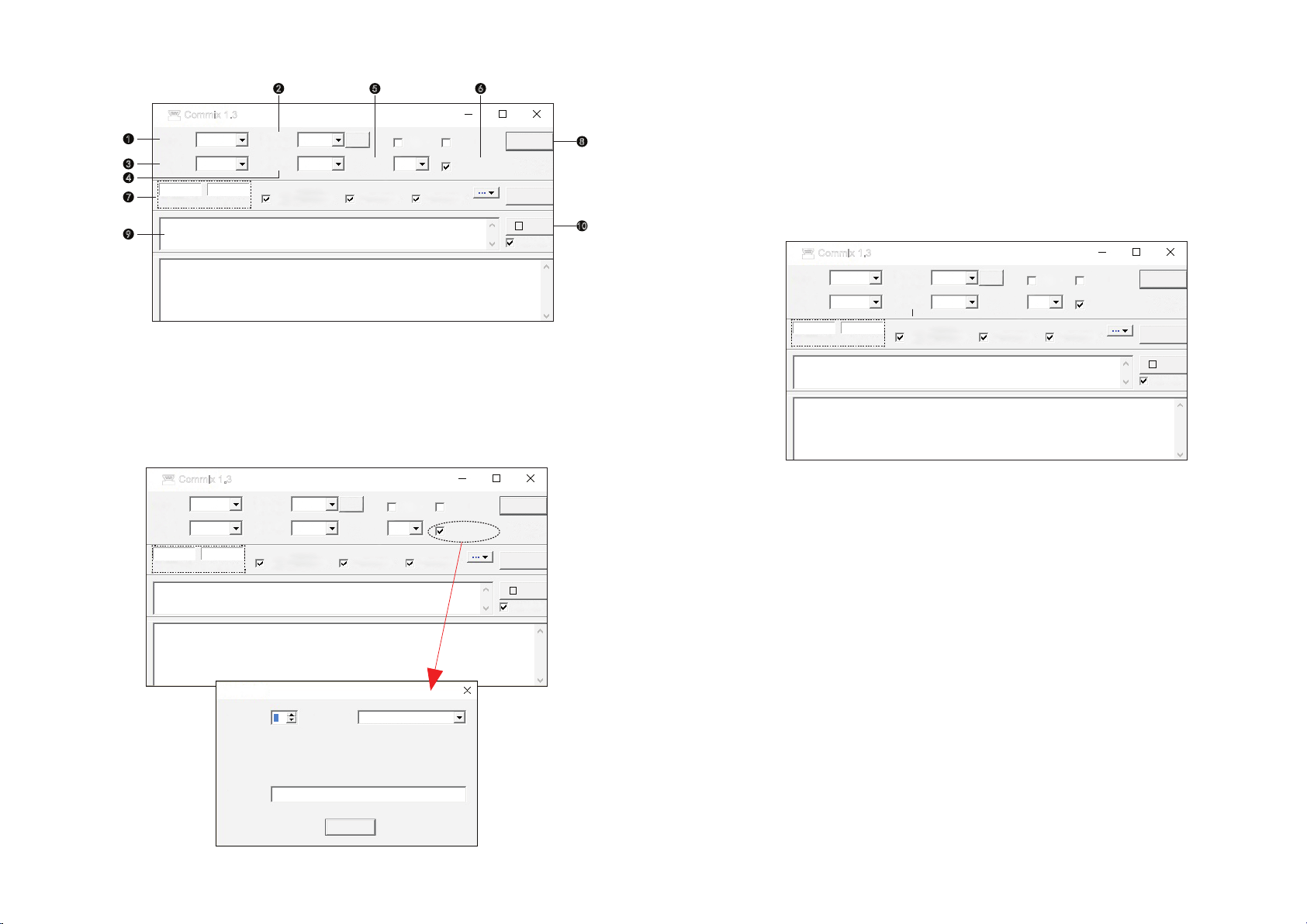
II. Send and receive
7. Configure the display mode of sending and receiving data; set to "HEX" display mode;
8. After configuring the above functions, open the serial port;
9. Enter the corresponding request message in the sending window, and the CRC will be automatically added;
10. Click Send to display the corresponding data in the receiving window;
Send the corresponding request message according to the communication protocol to obtain the corresponding
measurement or setting data. If you need to read the phase A voltage, you can use the following message to
access, as shown in the figure below.
1. Window 1 is the sending message input window; enter the requested message in this window,
note that the CRC is automatically added;
2. Window 2 is the message display window; the complete message received and sent is displayed in this
window: the green line is the request message sent by the master, and the blue line is the response
message returned by the slave.
Figure 3
01 03 40 00 00 02
01 03 40 00 00 02 D1 CB
(78 ms)
01 03 40 00 00 00 00 FA 33
25
COMMIX software instructions
1. Configure commix software
Figure 1
Figure 2
1. Set the serial port to be same as your computer; Example: set it to "COM1" if my computer's serial port is COM1.
2. Configure the baud rate; configure the corresponding baud rate according to the baud rate set by the meter,
such as 9600
3. Configure communication data bits; the default is 8 bits.
4. Configure the parity bit; the default is no parity, you can set "even parity" and "odd parity"
5. Configure stop bit; default 1 stop bit
6. Set the data verification mode; set to MODBUS-RTU verification mode, as shown in Figure 2.
Serial
port Baud
rate
1
3
7
9
4
2 5 6
8
10
CommixCommix 1.3
Serial
port COM1
8
Data bit
Input HEX
Input ASC
Display HEX
Display ASC
Ignore space
input Word wrap Display
interval
Baud
rate
Parity
bit Stop
bit
1
9600
Application
DTR RTS
ModbusRTU
Open
serial port
Pause
Clear
display
Send
Enter
E even
S
CommixCommix 1.3
COM1
8
Data bit
Serial
port
Input HEX
Input ASC
Display HEX
Display ASC Ignore space
input
Word wrap Display
interval
Parity
bit
Baud
rate
Stop
bit
1
9600
Application
DTR RTS Open
serial port
Pause
No
redundancy
check
Clear
display
Send
Enter
N
S
Redundancy check setting
Start byte Check
method CRC16(ModbusRTU)
Sure
Terminator
1
Table of contents
Other Toky Measuring Instrument manuals


Popular Measuring Instrument manuals by other brands


Agilent Technologies
Agilent Technologies 4339B Service manual

Hanna Instruments
Hanna Instruments HI96716C instruction manual

DUALPULSE
DUALPULSE DP490 instruction manual

Timewave
Timewave DM-1 operating manual

Aruba
Aruba 1 Series quick start guide

Met One Instruments
Met One Instruments BC 1054 Operation manual