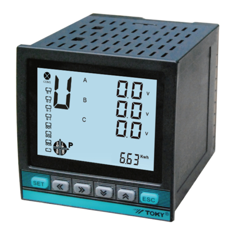
Toky FM Series User manual

KKFM-C01E-20220125
FM □ - R □ □
Set / Confirm key
Alarm indicator
Features:
→
Parameter selecting key
Hz:Frequency
RPS:Line speed
RPM:Tacho
SV
PV
AC/DC 100~240V±15%
<5W
AC 250V/3A or DC 30V/3A
DC 24V±2V 50mA max
≥100MΩ
Power supply:±2kV Input:±2kV
10~55Hz; 0.75mm
0~50℃35~85% RH
Square wave,Sine wave pulse signal:5V≤ High level ≤30V 0≤ Low level ≤1V
≥10kΩ
0.1~5000Hz
0.1%RD±3 Digits
Power supply
Power consumption
Relay capacity
External power supply
Insulation impedance
Anti-interference
Anti vibration
Environment
Input signal
Input resistance
measuring range
Accuracy
→
→
→
→
→
Press SET key for 5 seconds
Press RST key to select
Selecting measure tacho,
RPM lamp is on
Selecting measure line speed,
RPS lamp is on
Rate
Rate, Press RST key to refresh
the thumb switch value as the
new value.
Selecting measure frequency,
HZ lamp is on.
Range
Range setting, press RST to select
Display the refresh time,
Display the refresh time, press RST to select
Control mode,
Control mode,
press RST to select Measuring status
Key Lock,press the RST key to select
Key Lock
Hysteresis
Hysteresis, press RST to
refresh the value, the thumb
switch value is the new
hysteresis valule.
Relay 1 working mode
Relay 1 working mode,
press the RST key to select
normally open or normally
closed
*Above parameters are the conventional factory setting values of this instrument.
↓
—
—
—
—
↓
—
↓
SET
—
↓
SET
—
↓
—
—
SET
—
—
—
SET
—
—
—
—
↓
↓
↓
↓
↓
SET
↓
SET
↓
SET
↓
SET
↓
SET
↓
SET
↓
SET
↓
SET
↓
SET
↓SET
SET
SET
SET
—
—Measuring status
↓
2/Total 41/Total 4
FM Series of Frequency/Tacho/Line Speed Meter
FM Series of Frequency/Tacho/Line Speed Meter User Manual
II. Model
III.Technical Specifications
10:One Input
A:Display only B:One alarm C:Two alarm
R:Relay output
Dimension(mm):4:48H*48W 8:48H*96W
FM Series Frequency/Speed/Tacho Meter
FM4-A10(FM4-RL0)
Model Dimension(mm)LED Display digits Alarm
FM4-RB10(FM8-RL1)
FM8-A10(FM8-RL0)
FM8-RB10(FM8-RL1)
FM8-RC10(FM8-RL2)
48H*48W
48H*48W
48H*96W
48H*96W
48H*96W
4
4
5
5
5
NO
One AL2
NO
One AL2
Two AL1、AL2
I.Panel name
IV.Operation
1.Please study the instruction carefully and check if the connection is corret before power on.
2.The parameters can be set by the thumb switches and press keys.
SET: set and confirm key
RST: parameter selecting key
3.Operating process
◎Thumb switch setting,4-digit (FM4) or 5-digit (FM8) LED display,
◎Dimension(mm):48H*96W、48H*48W,
◎4 alarm modes(U-U),(U-d),(d-U),(d-d) selectable,
◎With return difference setting,improve the stability of instruments and systems,
◎Multi purpose use: it can be used as frequency meter, line speed meter and tachometer
through software selection,
◎High measurement accuracy, fixed or floating decimal point display can be selected.
Relay 2 working mode
Relay 2 working mode,
press the RST key to select
normally open or normally
closed

1、The input wire should not be too long. We suggest use the shielded wire to improve the anti-interference capacity. The instrument
should not use in the environment of high humidity (>90RH%) or high acidity.
2、Means overload range“UUUU”.
3、If the instrument is for display only, we suggest to set the measuring range(RAN)as float decimal point ( 99.9.9.9 ),refresh time display
set as 0(auto refresh)
If the instrument is for alarm output, it should be set as fixed decimal point,and select the two relay as NO or NC.
4、Malfunction handling:
A:displaying not stable, relay malfunction.
*Use the shielded wire, let the input signal under the situation without high interference.
*Set the decimal point correctly(RAN Manu).
*Use the pure power supply.
*Adjust the hysteresis corretly.
B:There is signal input, but the instrument displays 0.
*Check if the wire connection is corr ect.
*Check if the situation of diagrams is correct
*Check if the refresh time is correet.
FM4
←
←
←
←
←
←
←
←←
←
←
←
25
←
←
45+0.5
←
FM 4
AL 2
Hz RPS
RP M
RS T
SE T
99 9 9
FM8
FM4
96
←
←
←
←
91+0.5
-0
←
←
←
←
←
F M 8
←
30
Hz
RP S
RP M
SE T RS T
99 9
99
FM8
AL 1
AL 2
Refresh time display(s) Range Note
0.5
1
2
10
20
2Hz~5KHz
1Hz~5KHz
0.5Hz~5KHz
0.2Hz~5KHz
0.1Hz~5KHz
Refresh per 0.5 second
Refresh per 1 second
Refresh per 2 seconds
Refresh per 10 seconds
Refresh per 20 seconds
00.1Hz~5KHz Auto-Refresh
48 10 90 45+0.5 30
48
48
45
25
Function
selecting
Hz1
2
3
Rate
coefficient
(linear speed meter)
1.0000
4
Measuring
Range
99.9.9.9
Refresh time
Display
1(s)
6
7
8
5 Control Mode
U-U
U-d
d-U
d-d
U-U
Hysteresis
0-9999
(The decimal
point follows the
measured value)
0
Relay 1
working mode
Relay 2
working mode
N O 1、NC1
N O 2、NC2
NO1
NO2
9
0000
1111
3333
0000
Key
Protection
4/Total 43/Total 4
U - U
AL1
99999
SV2
0
AL2
H y↑
SV1
H y↑
U - d
AL1
99999
SV2
0
AL2
SV1
H y
↑
H y↑
d - U
AL1
99999
SV2
0
AL2
H y↑
SV1
H y
↑
AL1
99999
SV2
0
AL2
SV1
H y↑
d - d
H y↑
V.Dimension and Connection(Unit:mm)VII Example for usage
Form 1: Parameters
Form A: The relationship between measuring range and alarms.
No Parameter
code
Parameter
meaning Description
Setting the measuring range and press
RST key to select.
99999:1~5000Hz(Fixed decimal point)
9999.9:0.1~5000.0Hz(Fixed decimal point)
999.99:0.10~999.99Hz(Fixed decimal point)
99.999:0.100~99.999Hz(Fixed decimal point)
99.9.9.9:0.100~5000.0Hz(Float decimal point)
Press RST key to set the refresh time display
0.5:refresh per 0.5 second
1:refresh per 1 second
2:refresh per 2 seconds
10:refresh per 10 seconds
20:refresh per 20 seconds
Set the output mode,Press RST key to select
U-U:Up-Up
U-d:Up-Downd
d-U:Down- Up
d-d:Down-Down(Please refer Form A)
Set the alarm Hysteresis,Press RST key
torefresh the new setting value(SV2),
otherwise the value saved as the last time.
Set AL relay working mode,Press RST
key to select
NO1:Normal open NC1:Normal closed
Set AL relay working mode,Press RST
key to select
NO2:Normal open NC2:Normal closed
Select thumb protection level,
Press RST key to select
0000:No protection
1111:Thumb protection only,Press RST
keyto refresh, then the new value is available
3333:Protecting for factory use only, not for
users.
Setting rate value. Press RST key to
refresh the new rate value of SV2 and
change decimal point too. If don't press
RST key, the value saved as the last time.
Select the measuring function by pressing
RST key. HZ:frequency, HZ lamp on
RPS: line speed, RPS lamp on
RPM: tacho, RPM lam on
Range
Hz、RPS、
RPM
0.001~99.99
(FM4)
0.0001~999.99
(FM8)
99999
9999.9
999.99
99.999
99.9.9.9
0.5(s)
1(s)
2(s)
10(s)
20(s)
Factory
setting
VI 、Special note and simple malfunction handling
Note: Please connect cable according to the actual instrument wiring diagram.
5、Rate setting (P):The rate stands for the lengh of ench pulse.Line speed = frequency*P.
Frequency and Tacho does not have this rate.
Three
wire
proximity
sensor
+24V
FM FM
INPUT
GND
Red(Power)
White(Out)
Black(GND)
+24V
INPUT
GND
Red(Power)
Blue(Out)
470Ω~3KΩ
+24V RST
GNDINPUT
AC/DC
100~240V
POWER
OUT
COMNC NO
54321
10 9 8 7 6
GND INPUT
20 19 18 17 1 6 15 14 1 3 12 1 1
10 9 8 7 6 5 4 3 2 1
RST +24VGND
POWER
AC/DC 100~240V
AL1 AL2 OUT AG
~
←
←
88
←
12
Two
wire
proximity
sensor
This manual suits for next models
9
Other Toky Measuring Instrument manuals
