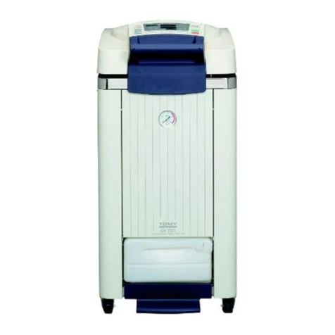
Tomy FLS-1000 User manual

FLS-1000
●Please read this Operator’s Manual thoroughly and understand the
contents before operating FLS-1000.
●This equipment is used for the handling of microorganisms, such as
bacteria and viruses, which can exert adverse health effects on human
beings or other living things, therefore, must be used by personnel
with enough knowledge and experience.
●Be sure to keep this Operator’s Manual handy for future reference.
OPERATOR'S MANUAL
AUTOCLAVE
FOR RESEARCH USE

ー1ー
TABLE OF CONTENTS
1.PRECAUTION FOR USE・・・・・・・・・・
・・
・・
1-1.About the Symbols・・・・・・・・・・・・・・・
1-2.Warnings and Cautions・・・・・・・・・・・
2.GENERAL INFORMATION・・・・・・・・・・・・
2-1.Operating Principles・・・・・・・・・・・・・・
2-2.Parts Identifications・・・・・・・・・・・・・・
3.INSTALLATION・・・・・・・・・・・・・・・・・・・・・・
3-1.
Moving and Installing the FLS-1000
・・・
3-2.Connecting to the Power Source
and Grounding・・・・・・・・・・・・・・・・・・
3-3.Setting the Altitude Level・・・・・・・・・
4.OPERATIONAL FLOW・・・・・・・・・・・・・・・・
5.OPERATION・・・・・・・・・・・・・・・・・・・・・・・・・
5-1.Turning On/Off the Power Switch・・
5-2.Opening and Closing the Chamber
Lid・・・・・・・・・・・・・・・・・・・・・・・・・・・・・
5-3.Checking the Pressure Gauge・・・・・・
5-4.Checking the Water Level in the
Exhaust Tank・・・・・・・・・・・・・・・・・・・・
5-5.Checking the Sterilizing Water in the
Chamber・・・・・・・・・・・・・・・・・・・・・・・・
5-6.Placing Articles to be Sterilized・・・・・
5-7.Setting Operating Parameters・・・・・・
5-8.Starting Operation・・・・・・・・・・・・・・・・
5-9.Ending Operation・・・・・・・・・・・・・・・・
5-10.Removing Articles to be Sterilized・
5-11.Draining the Sterilizing Water from
the Chamber・・・・・・・・・・・・・・・・・・・・
6.USEFUL FUNCTIONS・・・・・・・・・・・・・・・・・
6-1.Liquid Sterilization Function・・・・・・・
6-2.Memory Function・・・・・・・・・・・・・・・・
6-3.Check Function・・・・・・・・・・・・・・・・・・
6-4.Timer Function・・・・・・・・・・・・・・・・・・・
6-5.Power Failure Alert Function・・・・・・
6-6.Annual Inspection Reminder
Function・・・・・・・・・・・・・・・・・・・・・・・・
6-7.Setting the Time Unit for Display・・・
6-8.Selecting the Exhaust Setting for the
Liquid Sterilization Course・・・・・・・・
6-9.Setting the Temperature to Release
the Lid Interlock・・・・・・・・・・・・・・・・・
6-10.Sterilizing Water Change Alert
Function・・・・・・・・・・・・・・・・・・・・・・・
6-11.Exhaust Tank Illumination
Function・・・・・・・・・・・・・・・・・・・・・・・
7.OPTIONAL FUNCTIONS・・・・・・・・・・・・・・
8.ROUTINE MAINTENANCE・・・・・・・・・・・
8-1.Cleaning and Disinfecting the Main
Body・・・・・・・・・・・・・・・・・・・・・・・・・・・
8-2.Weekly Maintenance・・・・・・・・・・・・・・
9.TROUBLESHOOTING・・・・・・・・・・・・・・・・
9-1.Symptoms and Solutions・・・・・・・・・・
9-2.Error Code Table・・・・・・・・・・・・・・・・・
9-3.Contact Information・・・・・・・・・・・・・・
10.DISPOSAL AND TRANSFER・・・・・・・・・・
11.SPECIFICATIONS・・・・・・・・・・・・・・・・・・・
11-1.Specifications of the FLS-1000・・・・・
P.2
P.2
P.3
P.7
P.7
P.9
P.18
P.18
P.21
P.22
P.23
P.24
P.24
P.25
P.27
P.28
P.30
P.31
P.33
P.35
P.37
P.38
P.39
P.40
P.40
P.41
P.41
P.42
P.43
P.44
P.45
P.46
P.47
P.48
P.49
P.51
P.52
P.52
P.53
P.55
P.55
P.56
P.59
P.60
P.61
P.61

ー2ー
The TOMY Autoclave For Laboratory Use FLS-1000 has an inner vessel which is subject to
very high temperature and pressure during the operation. If this FLS-1000 is installed or
operated improperly, it may cause death or serious injury to the operator or people around,
or cause severe damage to FLS-1000 or other property. Be sure to read this Operator’s
Manual thoroughly before use, and follow its instructions and procedures for the proper use
of FLS-1000.
This Operator’s Manual uses certain words and symbols to call attention to important safety
and operational information. Safety indications are classified into “Warnings” and “Cautions”,
depending on the level of potential injury to personnel or damage to the equipment.
Indicates a potentially hazardous situation which, if not avoided,
could result in death or serious injury to laboratory personnel.
1. PRECAUTION FOR USE
WARNING
CAUTION Indicates a potentially hazardous situation which, if not avoided,
could result in minor or moderate injury to laboratory personnel
or damage to the product and surrounding property.
Denotes general ban or prohibition. The specific instruction is
described as an illustration or in a statement near the symbol.
Denotes general mandatory action. The specific instruction is
described as an illustration or in a statement near the symbol.
<Symbols>
1-1. About the Symbols

ー3ー
WARNING
Do not modify or alter the FLS-1000 or
any parts of the FLS-1000.
Failure to do so may cause serious accident
or malfunction.
When leaving the FLS-1000 out of use for
a long time, be sure to unplug the power
plug of the FLS-1000 from the outlet.
Failure to do so may allow insulation
to deteriorate, thereby causing electric
shock, short circuit or fire. For models
with no power plug provided, the power
circuit breaker to which the power plug is
connected should be turned off.
Do not use accessories or parts other than
those specified by the manufacturer.
Failure to do so may cause serious accident
or malfunction.
Do not install the FLS-1000 in a place
where chemicals that are likely to
generate flammable or corrosive gases or
fumes are stored.
Failure to do so may cause fire. Electric
components can corrode and cause short
circuit or electric shock.
Do not allow such foreign objects as
pieces of metal, combustible materials,
water or other liquids to enter the
interior of the FLS-1000 through its vents
or other openings.
Failure to do so may cause short circuit, fire
or malfunction.
Do not remove the outer panel of the
FLS-1000.
Contact with the inner parts of FLS-1000
may cause electric shock, burns, fire or
malfunction.
Do not touch the power plug with a wet
hand.
Failure to do so may cause electric shock.
Do not use any damaged power cord,
plug or loose outlet.
Failure to do so may cause accidental fire,
short circuit or malfunction.
Do not allow the power cord to be
pinched by or caught between heavy
objects.
Failure to do so may cause accidental fire,
short circuit or malfunction.
Avoid installing the FLS-1000 in a place
where there is a lot of dust or moisture.
Failure to do so may cause short circuit of
electric components or fire.
Avoid installing the FLS-1000 in or near
a sink or tap where there is a risk of it
being splashed with water.
Failure to do so may cause short circuit or
electric shock.
Install the FLS-1000 on a sturdy and level
surface such as concrete floors that can
support its weight.
Failure to do so may cause FLS-1000 to fall
over, thereby resulting in personal injury or
physical damage.
Do not unplug by pulling on the cord.
Stress to the cord may cause a loose
connection in the plug and result in fire or
burnout of the cord.
1-2. Warnings and Cautions

ー4ー
WARNING
Make sure that the FLS-1000 is properly
grounded.
Failure to do so may cause explosion,
electric shock or malfunction.
Never ground the FLS-1000 through a
water pipe or a gas pipe.
Failure to do so may cause explosion,
electric shock or malfunction.
Do not touch the power switch with a
wet hand.
Failure to do so may cause electric shock.
Never attempt to open the lid until the
chamber pressure returns to 0MPa.
If the lid is opened while pressure remains
in the chamber, articles to be sterilized or
steam may gush out, thereby resulting in
death or serious injury.
Do not bend the exhaust hose.
If exhaust venting is not carried out
smoothly, the chamber pressure may
become abnormally high, thereby causing
damage to parts. Broken parts may scatter
and cause burns, injury or serious accident.
When the pressure gauge is not working
properly, stop operation.
Otherwise, abnormality inside the
chamber, if any, cannot be found, thereby
causing serious accident. If pressure gauge
malfunction is suspected, please contact
your dealer or our local representative.
Be extremely careful of steam coming
out of the chamber when opening the
chamber lid.
Steam coming out of the chamber is very
hot and can cause burns or injury.
Do not use the FLS-1000 to sterilize
sealed articles.
Sealed articles may explode or burst when
they are removed from the chamber,
thereby causing burns, injury or serious
accident. The chamber pressure may
become abnormally high, thereby causing
damage to parts. Broken parts may scatter
and cause burns, injury or serious accident.
Do not sterilize any cracked or damaged
glassware.
Damaged glassware may explode or burst
when it is removed from the chamber,
thereby causing burns, injury or serious
accident.
Do not use the FLS-1000 to sterilize
flammable or explosive articles.
Failure to do so may cause fire or explosion.
Do not use extension cords or power
strips.
Failure to do so may cause accidental fire,
short circuit or malfunction.
Avoid leaving any foreign materials
between the chamber lid gasket and the
chamber.
Failure to do so may cause steam leak,
thereby resulting in burns.
Do not use the FLS-1000 to sterilize
corrosive articles.
Otherwise, the chamber may corrode and
explode or burst while pressure rises,
thereby causing death, injury or serious
accident.
Connect the FLS-1000 to a power outlet
of the voltage specified as correct for
FLS-1000. Do not connect it to a shared
outlet.
Failure to do so may cause accidental fire,
short circuit or malfunction.

ー5ー
WARNING
Make sure that holes inside the chamber
are not blocked by articles to be sterilized.
If the vent hole is blocked by such items
as sterilization bags, the chamber pressure
cannot be controlled, thereby causing
serious accident such as explosion of the
chamber. Make sure that articles to be
sterilized are placed in a container, such
as a basket provided with the FLS-1000 to
prevent the vent hole and its surrounding
area from being blocked.
Stop operation immediately when the
pressure gauge pointer is over the red
line.
Otherwise, parts can be damaged and
broken parts may scatter, resulting in burns,
injury or serious accident. In this case, stop
operation immediately and contact your
dealer or our local representative.
Use special caution when handling the
articles to be sterilized that may be very
hot after the operation.
Handling hot articles can cause burns.
Use special caution when handling the
hot liquid that may suddenly boil over.
The sterilized liquid inside the chamber is
cooled down slowly than the chamber and
may boil over suddenly on any shocks. This
bumping may cause burns or unexpected
accident.
Do not leave any contamination inside
the chamber or in the sterilizing water.
Failure to do so may cause corrosion or
damage on the chamber. It may also cause
malfunction of the water level sensor,
which may hamper the empty heating
prevention function, resulting in fire.
Be sure to unplug the FLS-1000 before
performing maintenance procedures.
Failure to do so may cause electric shock.
For models with no power plug provided,
the power circuit breaker to which the
power plug is connected should be turned
off.
Do not operate the FLS-1000 if any
corrosion, damage, deformation or loose
connections are found on its chamber,
chamber lid, hinges, hinge shafts,
retaining rings, lid hooks, or lid hook
catches.
Otherwise, explosion may occur while the
pressure rises, resulting in death, injury
or serious accident. If any abnormality is
found, please contact your dealer or our
local representative.
Do not operate the FLS-1000 if any crack,
deformation or damage is found on its
chamber lid gasket.
Otherwise, steam leak may occur, resulting
in burns. If any abnormality is found,
please contact your dealer or our local
representative.
After replacing the chamber lid gasket,
be sure to make a test run.
If the chamber lid gasket is not installed
properly, steam may leak and cause burns.
Unplug and inspect the power plug
regularly.
Failure to do so may cause fire or burnout.
Do not operate the FLS-1000 if the
chamber lid handle is deformed or
damaged.
Failure to do so may cause burns or injury.
If any abnormality is found, please contact
your dealer or our local representative.
Do not attempt to open the drain cock
unless the pressure gauge reads 0MPa.
If the drain cock is opened when pressure
still remains in the chamber, hot water may
spurt out, causing death, injury or serious
accident.

ー6ー
WARNING
When disposing or transferring FLS-1000
or its parts, FLS-1000 or the parts must
be appropriately decontaminated before
shipping it in any of the following cases:
In cases where FLS-1000 or any parts of
FLS-1000 has been exposed to infectious
and hazardous or radioactive substances.
In cases where FLS-1000 or any parts of
FLS-1000 has any residue of blood or
other chemicals and has been identified as
hazardous.
1:
2:
When returning FLS-1000 or any parts of
FLS-1000 for replacement or repair, FLS-
1000 or the parts must be appropriately
decontaminated before shipping it in any
of the following cases:
In cases where FLS-1000 or any parts of
FLS-1000 has been exposed to infectious
and hazardous or radioactive substances.
In cases where FLS-1000 or any parts of
FLS-1000 has any residue of blood or
other chemicals and has been identified as
hazardous.
1:
2:
Do not place hands on the top plate.
Otherwise, fingers or hands may get caught
in the chamber lid, resulting in injury.
CAUTION
Allow sterilizing water to cool down
sufficiently before draining water from
the chamber.
Water in the chamber or the exhaust tank
may be very hot after the operation, causing
burns.
Be careful of steam coming out of the
steam exhaust vent and its surrounding
area during the operation.
Hot steam may cause burns.
Allow chamber to cool down sufficiently
before performing maintenance work.
Otherwise, high temperature inside the
chamber may cause burns.
Make sure that there is no foreign
material in and around the lid gasket.
Otherwise, steam leak may occur, resulting
in burns. If any abnormality is found,
please contact your dealer or our local
representative.
Do not attempt to touch the outer panel
of the FLS-1000 during or immediately
after the operation.
Failure to do so may cause burns.
Keep away from the FLS-1000 while it is
in operation.
Failure to do so may cause burns. Please
keep at least 50 cm away from all four
corners of the FLS-1000 while it is in
operation.
Do not attempt to touch the exhaust tank
during the operation.
Failure to do so may cause burns.
Do not put hands into the top edge of the
rear panel.
Otherwise, fingers or hands may get caught
in the hinge area of the lid, resulting in
injury.
Be careful of the chamber or its
surrounding area after the operation
because it is very hot.
Failure to do so may cause burns.

ー7ー
2. GENERAL INFORMATION
2-1. Operating Principles
Autoclave or “High Pressure Steam Sterilizer” is an apparatus used to sterilize articles by
subjecting them to saturated steam under pressure above atmospheric pressure.
When the FLS-1000 starts operation, sterilizing water inside the chamber is heated up by the
element heater at the bottom of the chamber to generate steam.
The steam generated from heated water drives air out from the chamber and warms up the
interior of the chamber. When the temperature sensor inside the chamber detects that the set
sterilization temperature is reached, the set temperature is maintained for the set period of
time. The air remained inside the chamber is removed during this process. When the set time
has elapsed, the valve closes to start heating.
When the temperature sensor detects that the set temperature is reached, the timer starts to
maintain the set temperature. When the set sterilizing time has elapsed, the heater stops. The
sterilizing action is determined by the three elements: temperature, humidity and time that are
applied to articles to be sterilized during this process of the sterilization cycle.
When the chamber temperature drops, the valve opens to allow the pressure inside the
chamber to fall back to the atmospheric level. When the temperature sensor detects that the
chamber temperature falls to the set value for the lid interlock release temperature, the buzzer
sounds and the indicator turns on to indicate that the operation is completed.
If any abnormality occurs during the operation, the FLS-1000 enters safe mode, the display
shows an error code and the buzzer sounds.
During the sterilization process the temperature is maintained within +2℃ of the set
temperature. When the temperature drops below the set value, the timer countdown stops.
When the temperature exceeds the set value, the timer countdown starts again.

ー8ー
MEMO

ー9ー
2-2. Parts Identifications
<FLS-1000 Main Unit>
④
⑪
⑨
⑧
⑦
③
⑥
⑤
②
①
⑩
⑫
⑰
⑮ 、⑯
⑭
⑬

ー10ー
①
②
③
④
⑤
Chamber lid
It comprises an internal
chamber lid, a lid handle and
an outer covering including a
control panel. Open or close
this lid to place or remove
articles to be sterilized.
Chamber lid handle
It is used to open or close the
chamber lid
Pressure gauge
It displays the pressure
reading inside the chamber.
<Pressure display range>
0 〜0.4 MPa
Drain access cover
Door for access to the drain
outlet.
Exhaust tank
Steam exhausted from the
chamber is collected into this
exhaust tank. When the water
level in the exhaust tank is
between adequate levels, it
turns on blue. If the water
level is over maximum level,
it turns on red. It stays turned
on blue during the operation
regardless of the water level.
⑥
⑦
⑧
⑨
⑩
⑪
⑫
⑬
⑭
Lid-lock releasing pedal
It releases the lock of the
chamber lid.
Control panel
It is used to set or select
settings.
Safety valve access port
This opening/closing cover
provides access to the safety
valve for inspection.
Power supply switch
It is used to turn on or o the
power to FLS-1000.
Leakage breaker
It is a safety device and kept
on during normal operation.
Accessory case mounting hole
It is provided to mount the
accessory case for storing the
operator’s manual.
Main nameplate
Product Label
Power cord
⑮
⑯
⑰
⑱
⑲
Steam exhaust vent
The steam is discharged
from this vent after it passes
through the exhaust tank and
trap bottle.
Trap bottle
Exhaust steam is trapped in
this bottle.
Caster
One xed caster is mounted in
the corner on the side where
the chamber lid handle is
attached, and three swivel
casters in other three corners.
Level adjustment bolt
This bolt is mounted in both
sides of the lid-lock releasing
pedal. It is used to x FLS-
1000 in the horizontal position.
Safety valve
This valve is provided to
relieve excess pressure in the
chamber.
⑲
Safety valve
access port Screw fixation
position
⑱
Lid-lock
releasing pedal
⑰

ー11ー
⑳
㉑
㉒
㉓
Top plate
Lid hook
It locks the chamber lid in the
closed position.
Lid hook boot
Lid interlock switch
It activates the lid interlock.
㉔
㉕
㉖
㉗
Lid hook catch
Chamber lid
Chamber lid gasket
It maintains air-tightness of
the pressure vessel.
Lid xing nut
㉘
㉙
㉚
㉛
㉜
Safety valve hole
Chamber
Hinge
Hinge shaft
Retaining ring
㉓
㉗
㉘
㉔
⑳
㉒
㉑
㉙
㉕
㉖
㉛
㉚
㉜

ー12ー
㉝
㉞
Magnetic catch
Exhaust tank water level
sensor
It detects the water level of the
exhaust tank.
㉟
㊱
㊲
Exhaust tank
Air and steam exhausted from
the chamber is collected into
this exhaust tank.
Exhaust tank drain hose cap
Drain hose for exhaust tank
It allows water to drain from
the exhaust tank.
㊳
㊴
㊵
Exhaust tank cap
Drain cock
Drain hose for chamber
LOWER
UPPER
㊴
㊲
㊵
㊳
㉞
㉟
㉝
㊱

ー13ー
①
②
③
④
⑤
⑥
⑦
⑧
Access port
The temperature sensor for articles to be sterilized or the external temperature sensor can be
installed into the chamber through this port.
Temperature sensor
It detects the temperature inside the chamber.
Heating element (heater)
It heats the sterilizing water.
Vent hole
Air is discharged from the chamber through this hole. The hole leads to the exhaust tank, the
trap bottle, and the steam exhaust vent.
Water level sensor
It detects the level of sterilizing water in the bottom of the chamber.
Drain hole
Sterilizing water in the chamber is drained through this hole. The hole leads to the drain port.
Chamber bottom plate
It is provided to prevent articles to be sterilized from contacting with a heater at the bottom of
the chamber.
Water level indicator
It is provided to check the water level in the chamber.
<Chamber Interior>
①
⑥
②
⑤
④
⑧
⑦
③

ー14ー
<Piping Diagram>
PS
P
Pressure gauge
Pressure
sensor
M
Ball valve
Exhaust tank
Air release valve
Trap bottle
Safety valve

ー15ー
①
②
③
④
⑤
Exhaust speed level display
The exhaust speed level during
the temperature and pressure
falling process is indicated by
the number of turned on bars.
As more bars are turned on, the
exhaust valve opens wider and
the exhaust speed increases.
When it is not turned on, the
exhaust valve is closed.
Cooling fan display
It displays the setting of the
cooling fan to cool down the
chamber during the temperature
and pressure falling process. The
number of turned on indicators is
equivalent to the number of fans
that are operating.
External temperature sensor
indicator
It is used when the external
sensor for articles to be sterilized
is connected.
Timer indicator
It turns on when timer is set.
IN PROGRESS indicator
It turns while the FLS-1000 is
in operation. It lights up in red
when the chamber pressure
exceeds atmospheric pressure,
and in yellow when it falls below
atmospheric pressure.
⑥
⑦
⑧
⑨
⑩
⑪
Lid interlocked indicator
It turns on when the lid is closed
and locked. The lid cannot be
opened while it is on.
Lid open indicator
It turns on when the lid is opened
or the lid opening/closing detection
function does not detect the lid
position. The FLS-1000 cannot be
started while it is on.
Low sterilizing water level indicator
It turns on when the level of
water inside the chamber is low.
The FLS-1000 cannot be started
while it is on.
Drain indicator
It turns on when the exhaust tank
is full and must be drained. The
FLS-1000 cannot be started while
it is on.
Drain access cover open indicator
It turns on when the drain access
cover at the front of the main
body is opened. The FLS-1000
cannot be started while it is on.
Sterilizing water change indicator
It turns on when the water in the
sterilization chamber should be
replaced. Please refer to “6-10.
Sterilizing Water Change Alert
Function ”.
⑫
⑬
⑭
⑮
⑯
⑰
Temperature display
It indicates the set temperature
for the sterilization course while
the FLS-1000 is in standby mode,
and the chamber temperature
while it is in operation.
Time display
It indicates the set time for the
sterilizing course while the FLS-
1000 is in standby mode, and the
remaining operation time of the
course while it is in operation.
STERILIZE LIQUID indicator
It turns on when the liquid
sterilization course is selected.
STERILIZE indicator
It turns on when the sterilization
course is selected.
MEMORY indicator
It turns on when a preferred
sterilization course stored in
memory is selected. The indicator
of the sterilization course selected
for the preferred course lights up
at the same time.
STOP indicator
It turns on when the stop key is
pressed.
<Control Panel>
STOP
MEMORY
STERILIZE
LIQUID
START
FUNCTION
CHECK
TIMER
EXT.
SENSOR
COOLING
FAN
EXHAUST SPEED
FAST
TIME
TEMPERATURE
TIMER
READY
COMPLETED
POWER
FAILURE
STERILIZE
LID LID
WATER
DRAIN
COVER
CHANGE WATER
HR
MIN
°C
SLOW
STERILIZE
IN PROGRESS
①
⑥ ⑨ ⑩ ⑪
⑫
⑬
⑰⑯⑮
④
③
②
⑤
⑭
⑧⑦

ー16ー
A.
B.
C.
D.
Exhaust speed level setting keys
Press these up/down arrow
keys to change the level of
the exhaust speed. In the
liquid sterilization course,
the exhaust rate can only
be changed during the
temperature and pressure
falling process.
COOLING FAN key
Press this key to change the
cooling fan setting. In the
liquid sterilization course, the
setting can be changed during
the temperature and pressure
falling process.
EXT. SENSOR key
It is activated when the
external sensor for articles to
be sterilized is connected.
TIMER key
Press this key to select the
timer setting and display or
set the waiting time.
E.
F.
G.
H.
I.
FUNCTION key
Press this key to display or
set the useful function or the
optional function.
Temperature setting keys
Press these up/down arrow
keys to increase or decrease
the set temperature for the
sterilization cycle.
Time setting keys
Press these up/down arrow
keys to increase or decrease the
set time for the sterilization
cycle.
STERILIZE LIQUID key
Press this key to select the
liquid sterilization course
while the FLS-1000 is in
standby mode.
STERILIZE key
Press this key to select the
sterilization course while the
FLS-1000 is in standby mode.
J.
K.
L.
M.
MEMORY key
Press and hold down this
key in standby mode to save
the course setting currently
displayed in memory. Press
this key in standby mode
to select a preferred course
setting stored in memory.
CHECK key
Press this key in standby
mode to display the current
temperature. Press this key
during an operation to display
the set operating parameters.
START key
Press this key to start an
operation.
STOP key
Press this key to stop an
operation.
<Control Panel Keys>
STOP
MEMORY
STERILIZE
LIQUID
START
FUNCTION
CHECK
TIMER
EXT.
SENSOR
COOLING
FAN
EXHAUST SPEED
FAST
TIME
TEMPERATURE
TIMER
READY
COMPLETED
POWER
FAILURE
STERILIZE
LID LID
WATER
DRAIN
COVER
CHANGE WATER
HR
MIN
°C
SLOW
STERILIZE
IN PROGRESS
A.
L.
K.
F.
G.
M.
J.
I.
H.
E.
D.
C.
B.

ー17ー
①
②
③
④
Timer indicator
It turns on when the timer
setting is set. Please refer to
“6-4. Timer Function”.
Temperature rising process
indicator
It turns on to indicate that the
temperature rising process is
currently being performed.
Temperature and pressure
rising process indicator
It turns on to indicate that the
process of temperature and
pressure rise is currently being
performed.
Sterilization process indicator
It turns on to indicate that
the sterilization process is
currently being performed.
⑤
⑥
⑦
Temperature and pressure
falling process indicator
It turns on to indicate that the
process of temperature and
pressure falling is currently
being performed.
Temperature falling process
indicator
It turns on to indicate that the
temperature falling process is
currently being performed.
READY indicator
It turns on to indicate that
the FLS-1000 is ready for
operation.
⑧
⑨
POWER FAILURE indicator
It turns on to indicate that a
power failure occurs during
an operation. Please refer
to “6-5. Power Failure Alert
Function”.
COMPLETED indicator
It turns on to indicate that the
sterilization cycle is completed
normally. It begins to ash to
indicate that the operation is
completed normally and the
lid can be opened. It stays
on when the operation is
completed normally and the
chamber temperature drops
below 60℃.
<Work Monitor>
TIMER
READY
COMPLETED
POWER
FAILURE
STERILIZE
④
⑥
⑤
⑨⑧⑦
①
②
③

ー18ー
3-1. Moving and Installing the FLS-1000
3. INSTALLATION
WARNING
Do not install the FLS-1000 in a place where
chemicals that are likely to generate flammable
or corrosive gases or fumes are stored.
●Failure to do so may cause fire. Electric components
can corrode and cause short circuit or electric shock.
Avoid installing the FLS-1000 in a place where
there is a lot of dust or moisture.
●Failure to do so may cause short circuit of electric
components or fire.
Avoid installing the FLS-1000 in or near a sink or tap where there is a
risk of it being splashed with water.
●Failure to do so may cause short circuit or electric shock.
Install the FLS-1000 on a sturdy and level surface such as concrete
floors that can support its weight.
●Failure to do so may cause FLS-1000 to fall over, thereby resulting in personal
injury or physical damage.

ー19ー
To move the FLS-1000 hold the top of the unit on both sides of the chamber lid handle with
both hands and carefully push it.
※Four casters are mounted in the four corners of the bottom of the FLS-1000. A caster in the corner
where the chamber lid handle is attached on top is a xed one, and casters on each of the other
three corners are swivel ones.
※Never attempt to lift the FLS-1000 while it is being moved. This model is not designed to be lifted
up.
①
<To move and install the FLS-1000>
To install the FLS-1000 select a location in a room that is well ventilated and free of direct
sunlight.
Place the FLS-1000 onto a solid at surface such as a concrete oor.
※Weight of the FLS-1000 : 108kg
Avoid installing the FLS-1000 in a slippery place or a place which may be exposed to
vibration.
Considering the steam coming from steam exhaust vent and surrounding area, install
FLS-1000 providing a clearance of at least 25cm at the rear and on each side of the unit.
When operating the FLS-1000, the following environmental requirements should be met:
○
○
○
○
○
<Installation Location>
: 10 to 35°C
: 750 to 1060hPa
: less or equal to 75%
: below 2,000m
: 2 degrees
: Class II
: 2
Ambient temperature range
Atmospheric pressure range
Relative humidity
Altitude
Maximum gradient
Overvoltage category
Pollution degree
Table of contents
Other Tomy Laboratory Equipment manuals
Popular Laboratory Equipment manuals by other brands

Beckman Coulter
Beckman Coulter CytoFLEX Instructions for use

Velp Scientifica
Velp Scientifica AREX 5 instruction manual

Velp Scientifica
Velp Scientifica VTF F208B0063 instruction manual

REPLIGEN
REPLIGEN TangenX PRO PD LHV user guide

Teledyne
Teledyne 4700 Serivce guide

Showa Denko
Showa Denko Shodex ORpak CDBS-453 Operation manual

Thermo Scientific
Thermo Scientific TSQ Endura Hardware manual

Thermo Scientific
Thermo Scientific Sorvall MTX 150 instruction manual

Agilent Technologies
Agilent Technologies 7890A quick reference

Fisher Scientific
Fisher Scientific accuSpin 3 operating instructions

Heidolph
Heidolph MR Hei-Tec operating manual

GE
GE 800 user manual