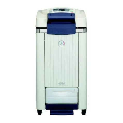
Tomy MX-307 User manual

OPERATOR'S MANUAL
HIGH SPEED REFRIGERATED MICRO CENTRIFUGE
MX-307
MX-207
MX-107
Before starting operation, read this manual thoroughly for a complete
understanding of the centrifuge and its correct operation.
Carefully store this operation manual conveniently to hand so that the
operator can consult it at any time.
●
●
FOR RESEARCH USE

— 1 —
7.FUNCTION(FUNC) KEY・・
・
・・
・
・・・
・
・・・
7-1.Setting the Rotational Radius(F0)・・
7-2.Setting the Adaptive Speed for the
Soft Brake(F1)・・・・・・・・・・
・
・・
・
・・
・
・・
・
7-3.Selecting the Flash Mode Pattern(F2)
7-4.
Setting the Speed in the Flash Mode(F3)
7-5.Setting the Buzzer Type(F4)・・・・・・・・
7-6.Setting the Buzzer Time(F5)・・・・・・・・
7-7.
Setting the Lid-up Monitoring Time(F6)
7-8.ECO Mode Shift Time Setting (F7)・・・
7-9.
Displaying the Total Time of the Run(d0)
7-10.
Displaying the Total Count of the Run(d1)
8.ROUTINE MAINTENANCE・・・・・・・・・・
8-1.
Cleaning and Disinfecting the Main Unit
8-2.Cleaning and Disinfecting the Rotor・
8-3.Monthly Maintenance・・・・・
・
・・
・
・・
・
9.TROUBLESHOOTING・・・・・・・・・・・・・・・
9-1.Symptoms and Solutions・・・・・・・・・・
9-2.Error Code Table・・・・・・・・・・・・・・・・
9-3.Contact Information・・・・・・・・・・・・
9-4.
Opening the Lid in Case of Power Failure・
10.DISPOSAL AND TRANSFER・・・・・・・・・・
11.SPECIFICATIONS・・・・・・・・・・・・・・・・
11-1.Acceleration and Deceleration
Times・・・・・・・・・・・・・・・・・・・・・・・・・
11-2.Cooling Capacity・・・・・・・・・・・・・・・・
11-3.Rotor Compatibility・・・・・・・・・・・・
11-4.Rotor Specifications and List of
Applicable Tubes・・・・・・・・・・・・・・・
11-5.Specifications of the
MX-307,MX-207 and MX-107・・・・・
1.PRECAUTION FOR USE・・・
・
・・
・
・・
・
・・
・
1-1.About the Symbols・・・・・
・
・・
・
・・
・
・・
・
1-2.Warnings and Cautions・・・・・・・
・
・・
・
1-3.Expected Lifetime of Rotors and
Buckets in Years or Cycles・・
・
・・
・
2.GENERAL INFORMATION・・・・・
・
・・
・
・・
2-1.Operating Principles・・・・・・・・・
・
・・
・
・
2-2.Parts Identifications・・・・・・・
・
・・
・
・・
・
3.INSTALLATION・・・・・・・・・
・
・・
・
・・
・
・・
・
・
3-1.Moving and Installing the Device・・・
3-2.Connecting to the Power Source and
Grounding・・
・
・・
・
・・
・
・・
・
・・
・
・・
・
・・
・
・
4.OPERATIONAL FLOW CHART・・・・・・
5.OPERATION・・・・・・・・・・・
・
・・
・
・・
・
・・
・
・・
5-1.Tourning On/Off the Power switch・
5-2.Opening/Closing the Chamber Lid・
5-3.Mounting/Dismounting the Rotor・・
5-4.Preparing Sample Tubes・・
・
・・
・
・・
・
5-5.Loading Samples・・・・・・・
・
・・・・・
5-5-1.Rack-In-Rotor・・
・・・・・・
・・
・
・・
・
5-5-2.Angle Rotor・・
・・・・・・・・
・・
・
・・
・
5-5-3.Swing Out Rotor・・
・・・・
・・
・
・・
・
5-6.Setting Operating Parameters・・・
・
5-7.Starting Operation・・・・・・・・
・
・・
・
・・
・
5-8.Ending Operation・・・・・・・・
・
・・
・
・・
・
5-9.Removing Sample Tubes・・
・
・・
・
・・
・
6.USEFUL FUNCTIONS・・・・・・・
・
・・
・
・・
・
・
6-1.Checking Operating Conditions
during the Run・・・・
・
・・
・
・・
・
・・
・
・
6-2.Changing Operating Conditions
during the Run・・・・
・
・・
・
・・
・
・・
・
・
6-3.Short Centrifuge Run with "Flash"
Key・・・・・・・・・・・・・・・
・
・・
・
・・
・
・・
・
・
6-4.Displaying the RCF・・・・・・
・
・・
・
・・
・
6-5.Memory Function・・・・・・・
・
・・
・
・・
・
6-6.Power Saving (ECO) Mode・・・
・
・・
・
P.2
P.2
P.3
P.7
P.8
P.8
P.9
P.13
P.13
P.16
P.17
P.19
P.19
P.20
P.21
P.23
P.26
P.27
P.30
P.31
P.33
P.35
P.37
P.37
P.38
P.38
P.38
P.39
P.39
P.41
P.42
P.43
P.44
P.44
P.44
P.44
P.45
P.45
P.45
P.46
P.46
P.46
P.47
P.47
P.49
P.50
P.53
P.53
P.54
P.55
P.57
P.58
P.59
P.59
P.60
P.61
P.63
P.81
TABLE OF CONTENTS

— 2 —
MX-307, 207 and 107 High Speed Refrigerated Micro Centrifuge employ a high speed rotating
rotor. Improper installation or misuse may cause death or severe personal injuries against the
user or people around and may result in serious damage to the instrument or other property.
Please read this Operator's Manual carefully and understand its handling before using the
instrument.
This Operator's Manual uses certain words and symbols to call attention to important safety and
operational information. Make yourself familiar with these safety symbols and follow the
instruction contained in it. The meaning of each symbol used in this Operator's Manual is given
below:
indicates a potentially hazardous situation which, if not avoided,
could result in death or serious injury to laboratory personnel.
1. PRECAUTION FOR USE
1-1. About the Symbols
WARNING
CAUTION
indicates a potentially hazardous situation which, if not avoided,
could result in minor or moderate injury to laboratory personnel or
damage to the product and surrounding property.
denotes general ban or prohibition. The specific instruction is
described as an illustration or in a statement near the symbol.
denotes general mandatory action. The specific instruction is
described as an illustration or in a statement near the symbol.
<Definition of another Safety Symbol>

— 3 —
1-2. Warnings and Cautions
WARNING
Do not modify or alter the MX-307,
207 and 107 or any parts of the MX-
307, 207 and 107.
Failure to do so may cause serious accident
or malfunction.
Do not unplug the MX-307, 207 and
107 by pulling on the cord.
Stress to the cord may cause a loose
connection in the plug and result in a fire or
burnout of the cord.
Do not use accessories or parts
other than those specified by the
manufacturer.
Failure to do so may cause serious accident
or malfunction.
Do not allow such foreign objects as
pieces of metal, combustible materials,
water or other liquids to enter the vent in
the MX-307, 207 and 107.
It may cause a short circuit, fire or
malfunction.
Do not remove the face panels of the
MX-307, 207 and 107.
If you touch inside the instrument, it may
cause an electrical shock, burn injury, fire,
or malfunction.
Do not touch the power plug with a
wet hand.
It may cause a serious or deadly electrical
shock.
Do not use any damaged power cord,
plug or loose outlet.
It may cause an accidental fire, short circuit
or malfunction.
Do not place the power cord under
heavy objects.
It may cause an accidental fire, short circuit
or malfunction.
When leaving the MX-307, 207 and
107 out of use for a long period of
time, be sure to unplug for safety.
Failure to do so may allow insulation to
deteriorate, thereby causing an electrical
shock, short circuit or fire.
Avoid installing the MX-307, 207 and
107 in a place where there is dust or
moisture.
Failure to do so may cause a short circuit of
electrical components or fire.
Avoid installing the instrument in
or near a sink or tap where there is a
risk of it being splashed with water.
Failure to do so may cause a short circuit or
electrical shock.
Install the MX-307, 207 and 107 on
a flat and level surface such as a
concrete floor.
Failure to do so may cause the instrument
to fall down, thereby resulting in injury to
laboratory personnel or damage to the
product and surrounding property.
Do not install the MX-307, 207 and
107 near chemical storage facilities
or sites likely to generate flammable
gases or fumes.
Electrical components can corrode and may
cause a short circuit or electrical shock.

— 4 —
WARNING
When returning the MX-307, 207 and
107 for refund or repair, please make
sure that the following procedures be
taken before shipping it.
When transferring or disposing of the
MX-307, 207 and 107 or any parts of
the MX-307, 207 and 107, please make
sure that the following procedures be
taken before shipping it.
If the instrument or any parts of the
instrument has been exposed to infectious
and hazardous or radioactive substances,
the instrument or the parts must be
appropriately decontaminated before it will
be accepted for further processing by our
repair technicians.
If the instrument or any parts of the
instrument has any residue of blood or
other chemicals and has been identied as
hazardous, the instrument or the parts must
be appropriately decontaminated before it
can be returned to our repair technicians.
1:
2:
Do not use extension cords or power
strips.
It may cause an accidental fire, short circuit
or malfunction.
Ensure that the MX-307, 207 and 107
is properly grounded.
Failure to do so may cause an explosion,
electrical shock or malfunction.
Never ground the MX-307, 207 and
107 through a water main or gas pipe.
Such grounding may cause an explosion,
electrical shock or malfunction.
Do not touch the power switch with a
wet hand.
It may cause a serious electrical shock.
Do not use the MX-307, 207 and 107
to centrifuge flammable or explosive
samples.
Failure to do so may damage the
instrument, thereby resulting in death or
serious injury to laboratory personnel. The
MX-307, 207 and 107 are not explosion-
proof models.
Do not use rotors or buckets beyond
their expected lifetime in years or cycles.
Failure to do so may result in the rotor or
bucket breaking during spinning.
Connect the MX-307, 207 and 107 to a
power outlet of the voltage specified
as correct for the instrument. Do not
connect the instrument to a shared
outlet.
It may cause an accidental fire, short circuit
or malfunction.
Do not use the MX-307, 207 and 107
to centrifuge infectious samples.
Failure to do so may cause serious or
potentially lethal diseases to laboratory
personnel. The MX-307, 207 and 107 are not
biohazard safety models.
If the instrument or any parts of the
instrument has been exposed to infectious
and hazardous or radioactive substances,
the instrument or the parts must be
appropriately decontaminated before
transfer or disposal.
If the instrument or any parts of the
instrument has any residue of blood or
other chemicals and has been identied as
hazardous, the instrument or the parts must
be appropriately decontaminated before
transfer or disposal.
1:
2:
Never open the lid while the rotor is
spinning.
Accidental contact with the spinning rotor
may cause a serious injury.
Be sure to unplug the MX-307,
207 and 107 before performing
maintenance procedures.
Failure to do so may cause a serious
electrical shock.

— 5 —
CAUTION
Do not move the MX-307, 207 and 107
with a rotor being mounted.
Otherwise, the motor shaft may bend,
thereby causing the rotor to fall off during
spinning.
Ensure that there is no damage or
foreign material on the motor shaft.
Otherwise, the rotor cannot be mounted
properly on the motor shaft, thereby
causing the rotor to fall off during spinning.
Ensure that there is no damage,
deformation or corrosion in rotors
and racks.
Otherwise, the rotor cannot be mounted
properly on the motor shaft, thereby
causing the rotor to fall off during spinning.
Ensure that there is no foreign
material in the rotor or in the
chamber before operating the MX-
307, 207 and 107.
If any, it may break a sample during
spinning and its broken pieces may scatter,
resulting in a serious accident. Or an
unbalanced load may occur, thereby
causing the rotor to fall off.
Ensure that the rotor is installed
securely on the motor shaft.
Otherwise, the rotor may come off during
spinning.
Do not use any damaged, deformed,
or corroded rotors, buckets, racks,
adapters or tubes.
Failure to do so may cause an unbalanced
load and may allow the rotor to drop off
during spinning.
Ensure that the maximum allowable
RCF of the tube.
Failure to do so may break the tube and
cause the rotor to fall off during spinning.
Do not exceed the actual maximum
achieved sample capacity for the
centrifuge tube.
An excessive capacity may cause sample to
spill during spinning and result in an
unbalanced load. It may apply excessive
force to the motor shaft, thereby causing the
rotor to fall off.
When the mass density of the
sample exceeds 1.2 g/cm3, the
revised maximum allowable speed
of the rotor should be calculated
respectively.
An excessive speed may damage the rotor,
bucket or rack, thereby causing the rotor to
fall off during spinning.
Load the rotor symmetrically around
the motor shaft. Opposing adapters,
tubes and samples should be of the
same type and tubes should be filled
equally.
Otherwise, it may cause an unbalanced
load and apply excessive force to the rotor,
thereby causing the rotor to fall off.
Ensure that no water drop or foreign
material is inside the tube hole.
Otherwise, unbalanced load may occur,
applying excessive force to the motor shaft,
thereby causing the rotor to fall off.
Ensure that the load of the tube or
sample is appropriately balanced.
Otherwise, unbalanced load may occur,
applying excessive force to the motor shaft,
thereby causing the rotor to fall off.
Be sure to attach the rotor lid to the
rotor if it is provided and make sure
it is surely secured and closed.
Otherwise, it may cause the rotor to fall off
during spinning.

— 6 —
CAUTION
Never run the MX-307, 207 and 107
with the rack sticking out the rotor.
Otherwise, the rack may come off during
spinning.
Check the type of the rotor and rack
before use to ensure the correct
combination is set.
Otherwise, it may cause damage to the
instrument. Please refer to the table of
“Rotor Rack Compatibility for Rack-in-
Rotor” in this Operator's Manual for proper
combination.
Ensure that the same type of buckets
are correctly mounted into all four
positions on the swing-out rotor.
Otherwise, it may apply excessive force to
the rotor, thereby causing the damage to the
rotor.
Ensure that all buckets on the swing-
out rotor are allowed to move freely
after loading sample tubes.
Otherwise, unbalanced load may occur
during spinning, applying excessive force
to the motor shaft, thereby causing the rotor
to fall off.
Do not exceed the maximum
allowable RCF of the tube.
Failure to do so may break the tube and
cause the rotor to fall off during spinning.
When the mass density of the sample
exceeds 1.2 g/cm3, do not centrifuge
at speed exceeding the maximum
allowable speed of the rotor which is
respectively calculated.
An excessive speed may damage the rotor,
bucket or rack, thereby causing the rotor to
fall off during spinning.
Avoid touching sharp edges on the
heat exchanger.
Otherwise, it may cause an injury.

— 7 —
1-3.
Expected Lifetime of Rotors and Buckets in Years or Cycles
WARNING
Do not use rotors or buckets beyond their expected lifetime in years or
cycles.
●Failure to do so may result in the rotor or bucket breaking during spinning.
The table below shows the expected lifetime of rotors and buckets for use in the MX-307, 207
and 107 in terms of years or cycles. When the rotor or bucket reaches the end of its expected
lifetime in years or cycles, stop its operation immediately and contact your dealer or local TOMY
representative. Operating environment can create abnormalities such as damage, deformation
or corrosion, which may reduce the lifetime of the rotor or bucket. If any signs of damage,
deformation or corrosion are present, stop using the rotor or bucket and contact your dealer or
local TOMY representative.
♦Expected lifetime in years:When the number of years listed in the table below has passed after delivery.
※Information on the lifetime is engraved on the rotor and bucket marked with an asterisk in the table.
Engraved mark example:[ Exp.08/2025 ] … It indicates the expiration date is August, 2025.
♦Expected lifetime in cycles:When the number of run cycles has reached the number of cycles listed in
the table below.
※When the rotor or bucket approaches its run cycle limit, error messages appear on the display.
Please refer to “9-2. Error Code Table.”
Rotors and buckets Lifetime in years Lifetime in cycles
TMP-21*, TMP-24* 10 years 50,000 cycles
TMA-22, TMA-27, TMA-29, TMA-30, TMA-32
TMA-26, TMA-25BH 10 years −
TMA-100, TMA-200, TMA-300 10 years −
TMS-1 10 years −
M0404-09, M0406-05, M0415-04 10 years −

— 8 —
2. GENERAL INFORMATION
2-1. Operating Principles
MX-307, 207 and 107 High Speed Refrigerated Micro Centrifuge are a device which separates a
sample solute from a solvent by way of the centrifugal force resulting from its rotation.
When the MX-307, 207 or 107 starts operation, the motor begins to drive and accelerate the
rotor, while the timer starts simultaneously. When the centrifuge reaches its set rotation speed,
it maintains the speed until the set operation time ends. The separation of samples is attained
by introducing centrifugal force generated by this rotor rotation. When the preset time elapses,
the motor starts deceleration. When the rotor stops rotation, the centrifuge emits a signal tone
and lights up the “STOP” lamp to indicate the centrifugation is finished.
While the centrifuge is powered on, it maintains the set temperature by cooling down inside
chamber using the refrigerator.
When an abnormality occurs in the centrifuge, it may return to a safer operation status and a
signal tone will sound and an error code will display.

— 9 —
2-2. Parts Identifications
MAIN BODY
③Chamber lid
②PUSH sticker
①Control panel
⑤Emergency lid lock
release hole
⑥Front cover
④Mounting hole
for acrylic case
⑦Inlet
⑧Drain hose/drain plug
⑨Caster
⑬Temperature sensor
⑪Chamber
⑩Motor shaft
⑫Chamber
lid gasket
⑭Lid hook
⑮Main power switch
⑯Power cord ⑰Power plug

— 10 —
Control panel
Operation of the instrument is controlled
on this panel.
PUSH sticker
When opening or closing the lid, press
the position to which this sticker is
attached.
Chamber lid
The chamber is closed by this lid. The
lid interlock cannot be released until the
rotor has come to a complete stop.
Mounting hole for clear acrylic case
This hole is to mount a clear acrylic case
for storing the accessories provided.
Emergency lid lock release hole
This hole is used to release the lid
interlock in case of power failure or any
malfunction. It is for emergency use
only.
Front cover
This cover is to protect the front of the
instrument.
Inlet
Air is inhaled through this inlet to the
refrigerating system.
Drain hose/drain plug
Condensation water in the chamber is
drained through this outlet.
Caster
These casters are used to move the
instrument.
①
②
③
④
⑤
⑥
⑦
⑧
⑨
Motor shaft
The rotor engages this motor shaft.
Chamber
It is used for centrifugation.
Chamber lid gasket
The sealing gasket prevents leaks
between the chamber and lid.
Temperature sensor
This sensor detects the temperature
inside the chamber.
Lid hook
The lid is locked in a closed position by
engaging this hook.
Main power switch
This switch is to turn on or off the power
to the instrument.
Power cord
Power plug
It is to connect the instrument to the
power outlet.
⑩
⑪
⑫
⑬
⑭
⑮
⑯
⑰

— 11 —
CONTROL PANEL
MEMORY
1
MEMORY
2
ECO
SOFT
BRAKE FUNC FLASH
TEMP TIME
SPEED
/RCF
DOOR
START
STOP
100rpm
100G
℃MIN
Memory indicator
lamp
①Temperature
display
②
Speed/RCF display
③
rpm/G unit indicator lamps
④
Time/Error code
display
⑤
Lid open indicator lamp
⑥
ECO indicator
lamp
⑦
Soft brake
indicator lamp
⑧Function indicator lamp
⑨Stop indicator lamp
⑫
Flash indicator lamp
⑩
Start indicator lamp
⑪
MEMORY
1
MEMORY
2
SOFT
BRAKE FUNC FLASH
TEMP TIME
SPEED
/RCF
DOOR
START
STOP
100rpm
100G
℃MIN
ECO
Memory keys
A. Temperature setting key
B.
Speed/RCF setting key
C.
Time setting key
D.
ECO key
E.
Soft brake key
F. Function key
G. Jog dial
H.
Flash key
I.
Start key
J. Stop/
Buzzer stop key
K.

— 12 —
Displays/Indicator Lamps
Memory indicator lamp
Lights up when the memory selected is
retrieved.
Temperature display
Indicates temperature inside the
chamber. It also indicates the actual
value when the temperature is not
setting.
Speed/RCF display
Indicates the speed or the RCF. It also
indicates the set value while the rotor
stops spinning and the actual value
while spinning.
rpm/G unit indicator lamps
Alternately light up to indicate either
speed “rpm” or RCF “G” is displayed.
Time/Error code display
Indicates centrifugation time. It
indicates the set value while the rotor
stops and the remaining run time while
spinning. When an abnormality occurs,
an error code is displayed.
Lid open indicator lamp
Lights up when the lid is opened.
①
②
③
④
⑤
⑥
ECO indicator lamp
Lights up when the power saving (ECO)
mode is selected.
Soft brake indicator lamp
Lights up when the soft brake is set.
Function indicator lamp
While this lamp is on, each display on
the control panel indicates information
on status different from the normal
mode. Please refer to “7. FUNCTION
KEY”.
Flash indicator lamp
Lights up when the ash key is pressed
to start a short time run.
Start indicator lamp
Flashes during acceleration. When the
rotor has reached the set speed, it stops
ashing.
Stop indicator lamp
Flashes during deceleration. When the
rotor has stopped spinning, it ceases to
ash.
⑦
⑧
⑨
⑩
⑪
⑫
Control Keys
Memory keys
Press this key to store or retrieve the
data of operating conditions.
Temperature setting key
Press this key to set the temperature.
Speed/RCF setting key
Press this key to set the speed or RCF
and to alternately display speed and
RCF.
Time setting key
Press this key to set the run time or to
check the set time during spinning.
ECO key
Used to select the power saving (ECO)
mode.
Soft brake key
Press this key to select the natural
deceleration mode at the set speed or
lower.
A.
B.
C.
D.
E.
F.
Function key
Used to perform specic settings. Please
refer to “7. FUNCTION KEY”.
Jog dial
Used to alter each setting. After pressing
each setting key, turn the jog dial
counterclockwise to decrease the value
or clockwise to increase.
Flash key
Used to start a short time run.
Start key
Used to start operation.
Stop/Buzzer stop key
Used to stop operation.
G.
H.
I.
J.
K.

— 13 —
3-1. Moving and Installing the Device
3. INSTALLATION
WARNING
Do not install the MX-307, 207 and 107 near chemical
storage facilities or sites likely to generate
flammable gases or fumes.
●Electrical components can corrode and may cause a short
circuit or electrical shock.
Avoid installing the instrument in a place where
there is dust or moisture.
●Failure to do so may cause a short circuit of electrical components or fire.
Avoid installing the instrument in or near a sink or tap where
there is a risk of it being splashed with water.
●Failure to do so may cause a short circuit or electrical shock.
Install the instrument on a flat and level surface such as a concrete
floor.
●Failure to do so may cause the instrument to fall down, thereby resulting in
injury to laboratory personnel or damage to the product and surrounding
property.
CAUTION
Do not move the MX-307, 207 and 107 with a rotor being mounted.
●Otherwise, the motor shaft may bend, thereby causing the rotor to fall off
during spinning.

— 14 —
Ensure that the rotor is not mounted in the
chamber.
Hold the upper side of the instrument rmly with
both hands and move it slowly.
①
②
<Moving and installing the device>
Choose a site for the instrument
that is well ventilated and free
of direct sunlight and install it
providing a clearance of at least
150mm at the rear and 100mm
on each side of the instrument to
ensure proper ventilation.
③
Insert the caster holder provided into the caster
to x it.
④

— 15 —
Install the MX-307, 207 and 107 where the following environmental requirements are met.
Temperature range : 10 to 35℃
Relative humidity : 30 to 85%(no dew condensation allowed)
Atmospheric pressure : 700 to 1060hPa
<Environmental Requirements>
Install the drain plug to drain hose.
※Otherwise, it may reduce cooling capacity.
⑤
Drain plug
Hang the clear case to store the accessories on the
side of the instrument with an attaching screw
supplied.
※Keep this Operator's Manual in the clear case for
future reference.
⑥
Operator's
Manual

— 16 —
3-2. Connecting to the Power Source and Grounding
WARNING
Connect the MX-307, 207 and 107 to a power outlet of the voltage
specified as correct for the instrument. Do not connect the
instrument to a shared outlet.
●It may cause an accidental fire, short circuit or malfunction.
Do not use extension cords or power strips.
●It may cause an accidental fire, short circuit or
malfunction.
Ensure that the MX-307, 207 and 107 is properly
grounded.
●Failure to do so may cause an explosion, electrical
shock or malfunction.
Never ground the MX-307, 207 and 107 through
a water main or gas pipe.
●Such grounding may cause an explosion, electrical
shock or malfunction.
The MX-307, 207 and 107 should be properly grounded, thereby protecting the operator against
electrical shock from the power outlet. If the necessary grounding is not provided in your facility,
contact a qualied electrician for arrangement of a proper grounding.
Protection against electrical shock is provided by connecting the protective grounding wire to the
ground terminal.
Connect the power plug to the proper outlet. Be sure to provide protective grounding.
15A/125V
※Unplug the power plug from the outlet when hearing thunder in order to prevent
lightning damage.
<Sample>
Rated voltage Power Requirements
110/120V 1 - Phase AC110/120V 50/60Hz 15A
220/230/240V 1 - Phase AC220/230/240V 50/60Hz 8A

— 17 —
4. OPERATIONAL FLOW CHART
P.23
1dengen
1dengen
1dengen
1dengen
1
Turning on the main power switch
1dengen
1dengen
2Mounting the rotor
1dengen
1dengen
3Preparing sample tubes
1dengen
1dengen P.26
4
Loading
sample tubes
1dengen P.33
1dengen
5
Setting the operational conditions
1dengen P.35
1dengen
6Starting operation
1dengen P.37
1dengen
7Ending operation
1dengen
P.
37
1dengen
1dengen
1dengen
8Removing sample tubes
1dengen P.21
1dengen
9Dismounting the rotor
1dengen P.19
1dengen
10
Turning off the main power switch
P.19
P.21
※For repetitive operations, restart the operation with "3. Preparing sample tubes" on the above
ow chart of the operation sequence after removing sample tubes.
※To continue operation after replacing the rotor, restart with the operation sequence of
"2.Mounting the rotor" on the ow chart after removing the operative rotor.

— 18 —
MEMO

— 19 —
5. OPERATION
5-1. Turning On/Off the Power switch
WARNING
Do not touch the power switch with a wet
hand.
●It may cause a serious or deadly electrical shock.
Before turning the power on, check that the instrument it is properly connected to the power
supply and grounded.
Turn the instrument on (a vertical line side [
┃
]) with the main power switch.
After turning the power on, the control panel will show the control program number.
※The control program number displayed differs according to the time of shipment.
<To turn the power switch on>
①
②
Turn the instrument off (a circle side [ ○]) with the main power switch.
<To turn the power switch off>
①
After approximately two seconds, the instrument will become operative.
The temperature, speed and time displays on the control panel show set values of previous
operation.
③
※Do not turn off power during centrifuge operation. If the instrument is turned off during spinning, it
will be inoperable until the rotor slows down naturally and comes to a complete stop. While the rotor
slows down, the interlock function prevents the chamber lid from being opened even if the power
switch is turned on.
※After turning the power off, wait at least ve minutes before turning it back on again.
This manual suits for next models
2
Table of contents
Other Tomy Laboratory Equipment manuals
Popular Laboratory Equipment manuals by other brands

Ametek
Ametek SEQUOIA Series Programming manual

Campbell
Campbell CNR2 instruction manual

Hettich
Hettich MIKRO 200 operating instructions

Scientific Industries
Scientific Industries MULTIPLATE GENIE SI-4100 operating instructions

Schuett Biotec
Schuett Biotec schuett solaris operating instructions

Hamilton Bahl
Hamilton Bahl VanGuard v6500 Operator's manual