Tonghui TH8400 Series User manual

O
OP
PE
ER
RA
AT
TI
IO
ON
N
M
MA
AN
NU
UA
AL
L
TH8400 Series
D
D
DC
C
C
E
E
El
l
le
e
ec
c
ct
t
tr
r
ro
o
on
n
ni
i
ic
c
c
L
L
Lo
o
oa
a
ad
d
d
C
C
Ch
h
ha
a
an
n
ng
g
gz
z
zh
h
ho
o
ou
u
u
T
T
To
o
on
n
ng
g
gh
h
hu
u
ui
i
i
E
E
El
l
le
e
ec
c
ct
t
tr
r
ro
o
on
n
ni
i
ic
c
c
C
C
Co
o
o.
..
,
,,
L
L
Lt
t
td
d
d.
..
A
A
Ad
d
dd
d
d:
:
:No.3, Tianshan Road, New District, Changzhou, Jiangsu
T
T
Te
e
el
l
l:
:
:(
(
(0
0
05
5
51
1
19
9
9)
)
)8
8
85
5
51
1
19
9
95
5
55
5
56
6
66
6
6,
,
,8
8
85
5
51
1
13
3
32
2
22
2
22
2
22
2
2
F
F
Fa
a
ax
x
x:
:
:(
(
(0
0
05
5
51
1
19
9
9)
)
)8
8
85
5
51
1
10
0
09
9
99
9
97
7
72
2
2
E
E
E-
-
-m
m
ma
a
ai
i
il
l
l:
:
:
S
S
Sa
a
al
l
le
e
es
s
s@
@
@t
t
to
o
on
n
ng
g
gh
h
hu
u
ui
i
i.
..c
c
co
o
om
m
m.
..c
c
cn
n
n
W
W
We
e
eb
b
bs
s
si
i
it
t
te
e
e:
:
:
h
h
ht
t
tt
t
tp
p
p:
:
:/
/
//
/
/
w
w
ww
w
ww
w
w.
..t
t
to
o
on
n
ng
g
gh
h
hu
u
ui
i
i.
..c
c
co
o
om
m
m.
..c
c
cn
n
n

TH8400 Series Operation Manual
1
Contents
Chapter 1 Overview......................................................................................................................3
1.1 Introduction..................................................................................................................3
1.2 Condition of Use..........................................................................................................3
1.3 Weight and Dimension.................................................................................................4
1.4 Safety Requirement......................................................................................................4
1.5 Electromagnetic Compatibility ....................................................................................5
Chapter 2 Panels...........................................................................................................................2
2.1 Introduction to front panel ...........................................................................................2
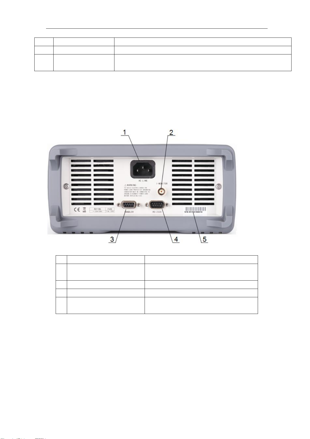
2.2 Introduction to rear panel.............................................................................................3
2.3 Introduction to display zone.........................................................................................3
2.4 Summary of the Displayed Page..................................................................................4
2.4.1 DISP (Function Display Page) .....................................................................4
2.4.2 SETUP (System Settings Page)....................................................................5
Chapter 3 Function Setting and Use.............................................................................................6
3.1 Static Mode (Static)......................................................................................................6
3.1.1 Constant Current(CC) ..................................................................................7
3.1.2 Constant Voltage(CV)..................................................................................7
3.1.3 Constant Resistance(CR)..............................................................................8
3.1.4 Constant Power(CP).....................................................................................8
3.2 Dynamic Mode (Dynamic) ..........................................................................................8
3.3 Sequential Operation (List)..........................................................................................9
3.4 CR-LED .....................................................................................................................10
3.5 Battery Test (Battery).................................................................................................11
3.6 Time Test(Timing)......................................................................................................12
3.7 Overcurrent Protection Test(OCPT)...........................................................................13
3.8 Over Voltage Protection Test(OVPT).........................................................................14
3.9 OPPT..........................................................................................................................15
3.10 Load Effect.................................................................................................................15
3.11 Sweep.........................................................................................................................17
3.12 Automatic Test (AUTO).............................................................................................18
Chapter 4 System Setup..............................................................................................................20
4.1 SYSTEM Setup (System) ..........................................................................................20
4.1.1 Language....................................................................................................20
4.1.2 Key Sound..................................................................................................20
4.1.3 Remote Compensation...............................................................................20
4.1.4 Start-up Parameters ....................................................................................21
4.1.5 Display Mode.............................................................................................21
4.1.6 Source under Test.......................................................................................22
4.1.7 External Analog..........................................................................................22
4.2 Load Unload (Von/Voff).............................................................................................22
4.3 Security Setting (Protect)...........................................................................................23
4.4 File Store....................................................................................................................24

TH8400 Series Operation Manual
2
4.4.1 Internal File Save .......................................................................................24
4.4.2 External File Call .......................................................................................25
4.4.3 Save Sampling Parameters.........................................................................25
4.5 Communication Setup (RS232) .................................................................................26
Chapter 5 Other Functions..........................................................................................................27
5.1 Short Circuit Test Function........................................................................................27
5.2 USB Interface Function..............................................................................................27
5.2.1 Copy Screen...............................................................................................27
5.2.2 STA File Save.............................................................................................27
5.2.3 CSV File Save............................................................................................27
Chapter 6 Interface and Communication....................................................................................28
6.1 Remote Control Interface...........................................................................................28
6.1.1 RS232 Interface Descriptions.....................................................................28
6.1.2 Communicate with a Computer..................................................................29
6.2 Command Specification.............................................................................................31
6.2.1 Command Structure....................................................................................31
6.2.2 Symbol Conventions and Definitions.........................................................32
6.3 Command Reference..................................................................................................32
6.3.1 Common Commands..................................................................................32
6.3.2 Instrument Commands ...............................................................................33
Chapter 7 Handler.......................................................................................................................48
7.1 Basic Information.......................................................................................................48
7.2 Operation Instruction .................................................................................................48
7.2.1 ON..............................................................................................................48
7.2.2 TRIG ..........................................................................................................49
7.2.3 VF/EXT-PROG..........................................................................................49
7.2.4 PASS/FAIL.................................................................................................49
Chapter 8 Technical Specifications ............................................................................................50
Chapter 9 Warranty.....................................................................................................................52
Chapter 10 Appendix....................................................................................................................53

TH8400 Series Operation Manual
3
Chapter 1 Overview
Thank you for purchasing and using our company's products. Before you use this instrument, please
confirm according to the "Complete set and warranty" in the last chapter of the manual. If there is
any discrepancy, please contact our company as soon as possible to protect your rights and interests.
1.1 Introduction
TH8400 series is a DC electronic load with high precision, high intelligence and easy operation.
This series of instruments integrates a variety of test functions, has excellent performance, and
adopts a liquid crystal screen display, which is clear and easy to operate. It can meet the needs of
rapid operation on the production site and the needs of high accuracy and stability in the
laboratory. .
The special functions and advantages of the instrument are as follows:
500kHz synchronous sampling, 0.1mA, 1mV resolution
Voltage/current ripple, peak, peak and valley measurement
A dozen measurement functions
Support remote compensation function
Support file storage function
480X272 pixels, 24-bit color, 4.3-inch color TFT LCD screen, used to set test conditions and
display of measurement results, etc.
Number keyboard and knob operation
High accuracy and high resolution
Low ripple and low noise
Intelligent fan control, save energy and reduce noise
Software control and detection can be done by computer
Dual-range programmable voltage and current load
1.2 Condition of Use
Power
Power supply voltage: 220V (1±10%)
Power frequency: 50Hz/60Hz (1±5%)
Power consumption: <50VA
Ambient temperature and humidity
Normal working temperature: 0℃~40℃, humidity: <90%RH
Reference working temperature: 20℃±8 ℃, humidity: <80%RH
Transportation environment temperature: 0℃~55℃, humidity: 93%RH
Preheat

TH8400 Series Operation Manual
4
Warm-up time after starting: ≥ 20 minutes
Points forAttention
(1) Please do not use it in bad environments such as dust, vibration, direct sunlight, corrosive gas,
etc.
(2) The instrument will not be used for a long time, please store it in the original packaging box or
similar box in a ventilated room with a temperature of 5℃~40℃and a relative humidity of not
more than 85%RH. The air should not contain a corrosion measuring instrument Harmful impurities,
and direct sunlight should be avoided.
(3) This instrument has been carefully designed to reduce the noise interference caused by the AC
power input, but it should still be used in a low noise environment as much as possible. If it cannot
be avoided, please install a power filter.
(4) There is a cooling fan at the rear of the instrument, and there are cooling vents on the left and
right to avoid the internal temperature rise affecting the accuracy. Please ensure that the instrument
is in a well-ventilated state.
(5) Do not switch the instrument frequently to avoid the loss of stored data.
1.3 Weight and Dimension
Dimension (W*H*D): 350mm*122mm*425mm
Weight: TH8412, TH8412A, TH8402 round 4.8kg,
TH8401, TH8411 around 3kg
1.4 Safety Requirement
This instrument is a Class I safety instrument
Insulation Resistance
Under the reference working condition, the insulation resistance between the power terminal and the
shell is not less than 50M;
Under humid and hot transportation conditions, the insulation resistance between the power terminal
and the housing is not less than 2M;
Insulation Strength
Under the reference working condition, the AC voltage between the power terminal and the housing
can withstand the rated voltage of 1.5kV and the frequency of 50Hz for 1 minute without
breakdown or arcing.
Leakage Current
Leakage current is not greater than 3.5mA.

TH8400 Series Operation Manual
5
1.5 Electromagnetic Compatibility
The power supply transient sensitivity is in accordance with the requirements of GB6833.4.
Conducted sensitivity is in accordance with the requirements of GB6833.6.
Radiated interference is in accordance with the requirements of GB6833.10.

TH8400 Series Operation Manual
2
Chapter 2 Panels
The content of this chapter is only a brief description. For specific operation and detailed
explanation, please refer to the corresponding content in Chapter 3.
2.1 Introduction to front panel
Figure 2-1 shows the front panel of TH8400.
Figure 2-1 Front panel
1
USB Interface
U Disk Interface
2
Trade Model
Display trademark, model and load parameters
3
LCD
480*272dot matrix LCD display, showing all measurement parameters, status,
measurement results, etc.
4
Left and right arrow keys
Used to move the cursor or turn pages
5
Knob
for moving cursor up and down and value adjustment
6
Numeric keypad
for entering values
7
[ON/OFF] Key
Load start or stop button
8
[DISP] Key
Enter the function setting page
9
[SETUP] Key
Enter the system settings page
10
[SHORT] Key
Shortcut key for short circuit test
11
[LOCK/LOCAL] Key
Used to lock the key to switch the remote control. When the key is on, the
keyboard is locked and the instrument can only be controlled remotely
12
[TRIG] Key
Trigger button for specific functions
13
[ENTER] Key
Confirmation button for numerical setting
14
(POWER)
Turn on or off 220V mains power, turn on the power when in the pressed
position; turn off the power when in the ejected position
15
SOFTKETs
The functions of the six keys in this part are not fixed, and correspond to the

TH8400 Series Operation Manual
3
functions of the soft key menu bar in the corresponding LCD screen.
16
INPUT
Load input port
17
Remote Compensation
(SENSE)
The instrument selects the measurement port for remote measurement
Table 2-1
2.2 Introduction to rear panel
Figure 2-2 shows the rear panel of TH8400.
Figure 2-2 Rear panel
1
Three-wire power socket
for connecting 220V/50HZ AC power supply
2
Current monitoring terminal
(I-MONITOR)
Used for current detection on the rear panel, output
(0-10V)
3
HANDLER
Instrument interface signal input and output port
4
RS-232C
Serial communication interface
5
Nameplate
Record production date, model, batch number,
manufacturer, etc.
Table 2-2
2.3 Introduction to display zone
TH8400 DisplayArea as shown in 2-3

TH8400 Series Operation Manual
4
(1) Title bar: displays the name of the current page.
(2) Information prompt area: real-time display of load prompt information or error information.
(3) Working mode display area: displays the working mode during static operation.
(4) Parameter setting area: used for parameter setting under the current function.
(5) Sampling display area: real-time display of various test results sampled.
(6) Status information area: display the current range of the load, short circuit, power part
temperature and other working status.
(7) Software menu area: corresponds to the soft keys on the front panel, and corresponds to various
operations according to the menu information.
2.4 Summary of the Displayed Page
2.4.1 DISP(Function Display Page)
Static operation (Const): Set CC, CV, CR and CP four basic load functions.
Dynamic operation(Dynamic): Make the load switch back and forth between two currents.
List operation (List): continuous programmable sequence load mode
CR-LED: Simulate the test function that the load is LED.
Battery test (Battery): Provide battery discharge test, support CC, CR and CP modes.
Time test (Timing): Provide time measurement in basic mode.
Over-current test (OCPT): Provide over-current protection function test.
Overvoltage test (OVPT): Provide overvoltage protection function test.
Overpower Test (OPPT): Provide overpower protection function test.
(Load Effect): Load function of test instrument or equipment.
Frequency sweep (Sweep): Vp+ and Vp- of test instruments or equipment under severe

TH8400 Series Operation Manual
5
conditions.
Automatic test (Auto): Programmable multiple test modes.
2.4.2 SETUP(System Settings Page)
System setting (System): Set the basic working mode of the instrument.
Von/Voff: Set the loading and unloading voltage of the instrument.
Protect: Set the protection value of the voltage, current and power of the instrument.
File (File): save the instrument parameters and data.
Communication Settings (RS-232): Set the communication parameters and methods of the
instrument.

TH8400 Series Operation Manual
6
Chapter 3 Function Setting and Use
This series of instruments integrates four basic modes of CC, CV, CR and CP and a variety of
advanced functions such as dynamic operation, battery test, load effect, frequency conversion
scanning and so on.
Operation method:
1. Press the DISP button on the front panel to enter the <Function Display> page.
2. Select the corresponding function through the soft key bar shown in Figure 3-1 below to enter the
setting page of the function.
3. The parameter setting area is shown in Figure 3-2. Rotate the knob to move the cursor to the
corresponding setting item, enter the value or select the corresponding function according to the soft
key bar.
4. Press the ON/OFF key, the load starts to work.
When the LCR function is applied, press [MEAS], the <MEAS DISPLAY> page will be displayed
on screen as shown in the following figure.
3.1 Static Mode (Static)
The static mode mainly includes four basic modes: constant current (CC), constant voltage (CV),
constant resistance (CR) and constant power (CP). After entering this page, select the desired
working mode.
Figure 3-1
Figure3-2

TH8400 Series Operation Manual
7
3.1.1 Constant Current(CC)
In this mode, no matter how the input voltage changes, the load will be pulled according to the set
current, so that the load works in a constant current mode.
Working current: the current value when the load is normally loaded
Rising slope: the rate of change of the current from 0 to the set value
Descent slope: the rate of change of current from set value to 0
3.1.2 Constant Voltage(CV)
In this mode, the load maintains the input voltage at a constant value by pulling the load current.
Working voltage: the input voltage when the load works normally
Rising slope: the rate of change of the voltage from 0 to the set value

TH8400 Series Operation Manual
8
3.1.3 Constant Resistance(CR)
In this mode, the load is equivalent to a constant resistance.
Working resistance: the load is equivalent to the resistance value.
3.1.4 Constant Power(CP)
In this mode, the load will be pulled with a constant power value
Working power: the load maintains a constant power value
3.2 Dynamic Mode (Dynamic)
The dynamic mode enables the load to switch back and forth between two set values. This function
can test the dynamic characteristics of the power supply. The principle is shown in the figure. The
current drops from Ib to Ia and is maintained for a period of time. The total time of the process is Ta,
and then rises from Ia to Ib and is maintained for a period of time. The total time of the process is
Tb. Switch back and forth in this way to test the dynamic characteristics of the power supply.

TH8400 Series Operation Manual
9
Set value-A: value of current Ia
Time-A: the total time of current from Ib to Ia (0.02mS~60S)
Setting value-B: current Ib value
Time-B: the total time that the current is maintained from Ia to Ib (0.02mS~60S)
Rise slope: the rate of change of current from low level to high level
Decline slope: the rate of change of current from high level to low level
Dynamic mode: continuous, pulse, flip
Continuous: The load will switch continuously between high and low load current according to the
set current, slope, and duration.
Pulse: Each time the trigger signal is received, the load current will change from Ia to Ib according
to the set slope for Tb time, and then return to Ia according to the set slope.
Rollover: Each time the trigger signal is received, the load current will change from Ia to Ib
according to the set slope. When the trigger signal is received again, the current changes from Ib to
Ia.
Number of repetitions: In continuous mode, the number of times the load current switches between
two set values
Unlimited: unlimited times.
User value: number of times in continuous mode, range 1 to 65535 times.
3.3 Sequential Operation (List)
The List function is used for the simulation of real loads or the editing of complex carrier shapes.
The loads are continuously loaded in sequence according to the sequence edited in the file. The load
supports up to 10 files, each file supports up to 100 steps, and each step can set the current load
value, duration and slope.

TH8400 Series Operation Manual
10
(1) File settings:
File: directly input the file to be programmed through the numeric keys
Working mode: the way of sequential loading in a single file
Continuous: continuous load sequence load
Counting: Every time a trigger signal is received, the load is pulled in sequence, and "counting"
cycles are repeated, and the loading stops after the end.
Single step: Each time the trigger signal is received, the load is loaded according to the next setting
parameter in the file.
Counting: in continuous mode, the list repeats the loading cycle and the range is 1 to 100.
(2) List settings:
Current: the load current of each step
Time: the duration of each step, the range is 20uS~50S
Slope: the current change rate from the previous step to this step
Figure 3-3
3.4 CR-LED
The load provides the LED simulation function. The LED equivalent circuit is shown in the
following figure, which is a series of resistance Rd and voltage source Vf. Its VI curve is equivalent
to the tangent of the real LED nonlinear VI curve at the operating point (Vo,Io).

TH8400 Series Operation Manual
11
Turn-on voltage (Vo): LED forward working voltage at forward working current Io
It can be obtained from the VI curve in the LED specification. The real load is usually a series
connection of n sections of LEDs, so Vo should be set to n times the parameters of a single section.
On current (Io): forward current at the operating point, ie the rated output current of the LED
Rd coefficient (Rd Coeff): the ratio of the series equivalent resistance (Rd) and the total
equivalent resistance of the LED load (Vo/Io)
Rd Coeff = Rd/(Vo/Io)
Users only need to set the above three parameters according to the LED specification, and then
adjust it arbitrarily within the output voltage range of the LED power supply, and then the real LED
analog load test can be performed.
3.5 Battery Test (Battery)
The load provides battery power test function. The discharge conditions support three modes of CC,
CP and CR. There are three conditions of voltage/capacity/time to stop discharge. You can choose to
set up. As shown in Figure 3-4, after starting the test, the load displays the discharge duration,
accumulated AH battery capacity and WH battery capacity, when the stop condition is met, the load
completes the test and stops loading.

TH8400 Series Operation Manual
12
Mode: The load supports three discharge modes of CC, CR and CP
Loaded value: loaded parameters, according to the discharge mode, respectively current,
resistance and power
Stop condition: select voltage, time, battery capacity (Ah) and battery capacity (Wh)
Threshold: according to the selected stop condition, when the threshold is met, the discharge
ends
3.6 Time Test(Timing)
The load provides a time test function with a test accuracy of 0.1mS. The load is measured under the
predetermined loading conditions, and the time interval is measured according to the two signals at
the beginning and the end. Figure 3-5 is the test result display zone.
Figure 3-4

TH8400 Series Operation Manual
13
Figure 3-5
Working mode: CC, CV, CR, CP and OFF can be selected in load mode
Set value: the load value set according to the working mode
Starting condition: Trigger timing signal, optional voltage, current or external trigger signal
Starting edge: select the starting trigger mode, selectable rising edge or falling edge
Starting value: when the starting condition is voltage or current, the corresponding trigger
value
End condition: signal to end timing, optional voltage, current or external trigger signal
End Edge: End trigger mode selection, selectable rising edge or falling edge
End value: when the end signal is voltage or current, the corresponding trigger value
3.7 Overcurrent Protection Test(OCPT)
The load provides the overcurrent protection test function. The principle is shown in the following
figure. The load starts from the initial current (I-Start) and gradually increases the current to the
cut-off current (I-End) according to the set steps (Steps). When it detects that the input level drops to
the trigger level (V-Trig), it is considered that the source under test has achieved OCP protection. As
show in Figure 3-6, during this process, the load not only detects the OCP protection point, but also
captures the power of the maximum power point. , Voltage and current values.

TH8400 Series Operation Manual
14
Starting current: the current value when starting to load
Cut-off current: the current value after ending load
Increasing steps: the total steps of increasing current from the beginning to the end, range
1~1000
Residence time: the duration of single-step current
Trigger level: confirm the level value that triggers overcurrent protection
Load lock: choose whether to continue loading after the test
Close: End the load after the test is completed.
Open: Continue to load after the test is completed.
3.8 Over Voltage Protection Test(OVPT)
The load provides over-voltage protection (OVP) test function. The principle is as shown in the
figure below. The load captures the peak point and the falling edge of the input voltage and triggers
at the preset level (V-Trig) at the moment of the falling edge. As shown in Figure 3-7, during this
process, the voltage The peak value is the overvoltage protection point (OVP) of the power supply
under test, and the time from the peak value to the trigger level (V-Trig) is the OVP response time
(Tovp) of the power supply under test.
Figure 3-6

TH8400 Series Operation Manual
15
Trigger level: confirm the protection voltage should be higher than the output voltage after the
measured source voltage is protected
3.9 OPPT
The load provides power protection test function, the principle is the same as 3.7 over current test
(OCPT).
3.10 Load Effect
The load provides a load effect test function. During the test, the load will be loaded under 3
Figure 3-7
This manual suits for next models
5
Table of contents
Other Tonghui Test Equipment manuals

Tonghui
Tonghui TH2840 Series User manual

Tonghui
Tonghui TH2883S4-5 User manual

Tonghui
Tonghui SM6029 User manual

Tonghui
Tonghui TH2883-5 User manual

Tonghui
Tonghui TH2523/A User manual

Tonghui
Tonghui TH9310 Series User manual

Tonghui
Tonghui TH8200 Series User manual

Tonghui
Tonghui TH9010 Series User manual