Toolex 594102 User manual

INSTRUCTION MANUAL
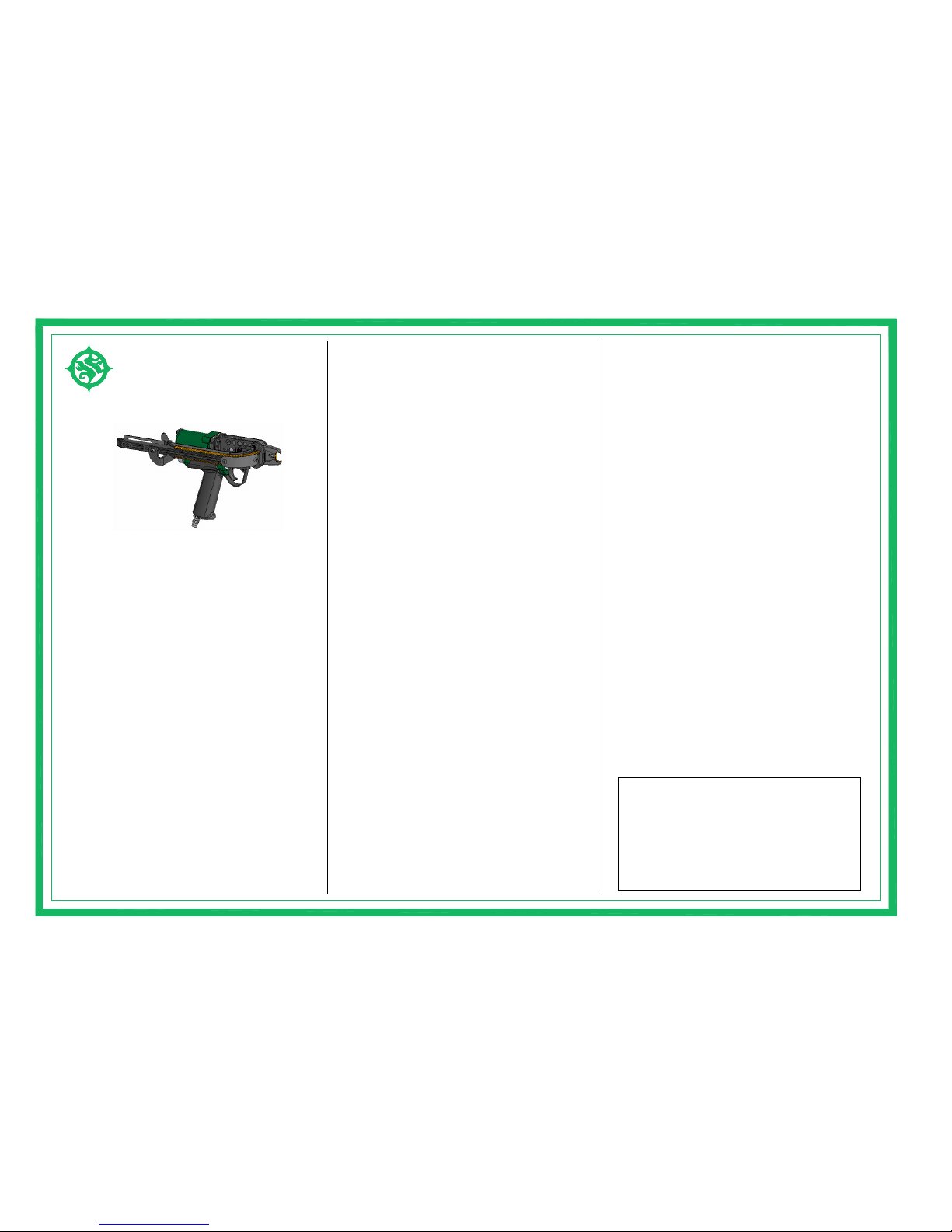
594102
AIR HOG RING STAPLER

1
1
2
1
47,48,49
Assembly
NO.202 NO.203 NO.200
NO.201
NO.205
Pusher Assembly
68,69
12,29,30,31,32,47,48,49,89
Assembly Frame Assembly
20,35R,35L,36,37,86 23,27,28
Housing Assembly
39 Socket Head Cap Screw AC01039 4
80 Guard
83 Screw
82 Clip Anti-Backup
86 Plate Screw
89 Flexloc Nut
204 Feeder Guid Rail
78A Magazine Shim
79 Washer
81 Guard Screw
67 Nut
70 Pusher Spring
74 Jaw Bolt
71 Button Head Screw
75 Magazine Spring
73 Magazine Body
78 Magazine Shim
77 Roll Pin
76 Magazine Shoe
64 Socket Head Cap Screw
68 Pusher
69 Extruded Rivet
59 Inlet Bushing
AC0178A
AC02082
1
AC02083
1
AC01089 3
AC01086
1
AC02080
AC02081
1
AC01079
2
AC02204
AC01059
1
AC02068
1
AC01069
1
AC02073
AC02074
2
AC02077
1
AC01078
1
AC02076
1
AC02075
2
AC01071
1
AC01070
1
AC01064
1
AC01067
1
57 Nut
47 Feeder Blade
49 Roller Pin
48 Piston Rod
56 Washer
51 Feeder Arm
58 Screw
50 Lower Jaw
45 Latch
41 Jaw Bushing
43 Latch Pin Clip
44 Latch Spring
46 Roller
40 Upper Jaw
AC02048
AC04050
AC03050
AC02050
1
1
AC01056 2
AC01057 4
AC01058 2
AC01051 1
AC03048
1AC03048
AC01049
AC03047
AC03047 1
AC02
AC02
AC03
AC04
AC03
AC04
AC04
AC03
1
AC02047
AC02046
AC01046
4
AC01046
AC03045
AC03045 1
AC04040
AC01041
1
AC01045
1
AC01043
AC01044
2
AC03040
AC02040
AC02
AC04
AC03
AC02
AC04
AC03
AC02
AC04
AC03
AC02
1
AC01007
7 Throttle Spring
23 Stud
30 Piston
28 Set Screw
29 O-Ring
31 Cylinder Gasket
27 Housing
35L Side Plate (Left)
35R Side Plate (Right)
37 Trigger
36 Roll Pin
32 Piston Stop Spacer
11 O-Ring Support
12 O-Ring
17 Throttle Stem
16 Front Valve Seat
10 Valve Screw Washer
20 Trigger Guard
21 Flexloc Nut
18 Button Head Cap Screw
8 Throttle Spring Locator
9 Throttle Valve Screw
13 O-Ring Center Support
14 Throttle Valve Spacer
2
AC01023
AC01028
AC01032
AC01032
AC02032
1
AC01036 3
AC01037 1
AC0135R
AC0135L
1
1
2
1
1
1
AC01029
AC01030
AC01031
1AC01027
AC04
AC03
AC02
1AC01008
4
1
5
2
1
1
1
2
2
AC01011
AC01014
AC01012
AC01013
AC01018
AC01017
AC01016
AC01009
AC01010
1
2
AC01020
AC01021
ITEM DESCRIPTION
1 Set Screw
5 Rear Valve Seat
4 Air Deflector
3 Shakeproof lock Washer
6 O-Ring
NO.
TOOL
7
1
1
1
PART
AC01003
NUMBER
AC01001
AC01005
AC01004
2AC01006
Q'TY
NO.206
73,75,76,77,80,81,82,83
Magazine Assembly
AC02 & AC03 & AC04
clearance; then, after tightening the Cap Screws (#74 x 2 pcs),
Remove Cap Screws (#18 & #39 x 4 pcs) and Frame Assy. (203)
which to do it .Obviously, the less the tool is abused, the better.The
to remove Valve units. One Valve will stay on Spacer (#14) and can
complete Valve Assembly (should then have free motion of about
second Valve mounted on Screw (#9) in from other side and
Assemble one Valve on Spacer (#14). Holding Allen wrench, bring
#16). Using two Allen wrenches, unscrew Throttle Valve Screw (#9)
Loosen Set Screws (#28) and remove Adjustable Valve Seats (#5 &
Rollers (#46 x 4 pcs) can be taken out the front end of the Frame.
Spacer (#32). Piston Rod Assembly with Feeder Blade (#47) and
from Cylinder Housing. After taking off Piston(#30) and Piston Stop
the operating speed of the tool and may cause damage to it.
using 1/4" (6.35mm) ID air hose. Higher pressures will not increase
Air pressure should be maintained at 85-96 PSI (5.98-6.68 kg/cm2)
AIR PRESSURE
tool for a long and useful work life.
Please take care in handling, operation and maintenance of your
matter that is inside the tool will reduce its Operational efficiency.
cycling completely. Obviously, moisture, dirt or any other foreign
check to make sure that the application is correct and that the tool is
fastener. If for any reason you are not getting complete closure,
also note that the tool should make a complete closure of the
Far when you use it in the direction of your application. Please
tool should be handled firmly in your hand and don't stretch too
TO ASSEMBLE
1/16").
be disassembled after removal from Housing.
THROTTLE
PRECAUTIONS MAY RESULT IN SERIOUS
MAY RESULT. FAILURETO FOLLOW THESE
AWAY FROM ALL MOVING PARTS. INJURY
THE FRONT OF JAWS OF THE TOOL AND
KEEP HANDS AND CLOTHING AWAY FROM
DO NOT POINT THE TOOL AT ANY PERSON.
INJURY.
clearance should be rechecked.
promptly from stock. PLEASE SEE C-RING STYLES CHART
and #50). Remove Magazine Assembly(#73) and Feeder Guide Rail
Remove Flexlock Nuts(21) and Jaw Bolts (#74).Take out Jaws(#40
request. Use only parts that are specifically fabricated for the AC
replacement parts for repairs. Parts price lists are available upon
and have it checked for proper operation. ANN-CHAIN will ship
If any tool is not operating properly, remove it from service at once
for further details regarding materials, points and size of C-RING.
These rings are available from ANN-CHAIN and will be shipped
oiled, periodic oiling in small amounts may increase the serviceable
Although the jaws and other moving parts of the tool do need to be
A good grade of oil that emulsifies in water is recommended for air
Lubricators and Filter Units for proper lubrication and clean, dry air.
To insure long, trouble-free service, we recommend Air Line
moisture in the air line will adversely affect the smooth operation
sufficient to provide a constant and even flow of clean, dry air. The
The air line should have an attached air line filter and regulator
filter should be installed as close as possible to the tool. Dirt or
PNEUMATIC CLIP RING TOOL AC02, AC03,AC04
to take a long, hard look at your work and choose the best way in
a variety of other things. The most important point to remember is
a group of wire, the tool is frequently used as a pusher puller and/or
into foam, it should be cleaned occasionally. Also, when"grabbing"
area of maintenance to be conscious of is when pushing the tool
this is like any other tool and should be properly maintained. One
It should be kept in mind that in using the air powered clip ring tool,
in most operations the tool is used 90 degrees to the work performed.
The air powered clip ring tool should be held firmly in the hand and
OPERATION
and shorten its useful life.
proper operational precautions may result in damage to your tool
is of high quality and made to exacting standards, failure to follow
pressures above 100 PSI (7.03 kg/c
dirt and other foreign matter and do not operate the tool at air
working order, do not drop the tool, keep the mechanism free from
For best operating results and long life, maintain the tool in good
OPERATING INSTRUCTIONS & PARTS LIST
). Although your clip ring tool
Feeder Blade, Rollers and Piston Rod
Jaws, Magazine, Feeder Guide Rail
TO DISASSEMBLE
model tool which you own.
(#204).
REPAIR AND SERVICE PARTS
C-RINGS
TEL: 886-4-7521297 FAX: 886-4-7521293
CHANG HUA CITY, TAIWAN, R.O.C.
NO.65-5, LANE 540, YOAN-FONG RD.,
ANN-CHAIN ENTERPRISE CO., LTD.
LUBRICATION
life of the tool that receives heavy use.
MANUAL OILING
tools.
of the tool and decrease its serviceable life.
AIR FILTER AND REGULATOR
Spacer (#32), Piston (#30) and Flexloc Stop Nut (#21). Insert
Magazine must be held tight against Side Plate while checking this
clearance between Magazine Shoe (#76) and Feeder Blade (47).
between Magazine (#73) and Side Plate (#35R) to produce a
Before tightening Cap Screws (#74), insert enough Shims (#78)
ADJUSTMENT OF MAGAZINE
(#41 x 2 pcs) into Jaws (#40 & #50), side jaws into place and
Assembly Latch(#45) and Latch Pin Clip (#43).Insert Jaw Bushings
(#64) tight. Continue turning to desired Pusher Spring tension and
Pusher spring (#70), slide into Bracket and insert lower Cap Screw
With Feeder Arm (#51) in place, assemble Feeder Guide Rail(#204).
Throttle Stem (#17) and then assemble Frame to Housing.
MAGAZINE
complete assembly.
FEEDER GUIDE RAIL
lock with Nut (#67).
2pcs) and Rollers (#46 x 4 pcs). Put in Frame. Mount Piston Stop
Onto Piston Rod (#48) mount Feeder blade (#47), Roller Pins(#49 x
FEEDER BLADE, ROLLERS, PISTON ROD
Piston (#30) and Piston O-Ring (#29).
off Adjustable Valve Seat until leak stops. If leaks do not stop, check
be raised from its Bushing Seat, causing air leakage. To correct back
If an Adjustable Valve Seat is turned too far, the opposite Valve will
TO LOCATE AND CORRECT AIR LEAKS
Handle. After finer adjustment, lock Valve Seats in place with Set
Front Valve Seat (#16), turning until air stops exhausting through
leaking through Valve. Using Throttle Stem (#17) to turn, install
front Valve closed with a 3/8" dia. turn Valve Seat in until air stops
Adjustable Valve Seat (#5). With air partly turned on and holding
With Throttle Spring Locator (#7 & #8) in place, partially screw in
THROTTLE VALVE ADJUSTMENT
Screws (#28) in Housing casing.
Table of contents
Other Toolex Power Tools manuals


Popular Power Tools manuals by other brands


ABB
ABB T&B Tools TBM12PCR-LI operating instructions

Parkside
Parkside PES 200 B1 Operation and safety notes

Metabo HPT
Metabo HPT WR 18DBDL2 Safety instructions and instruction manual

DeWalt
DeWalt XR DCH614X2 Original instructions

DeWalt
DeWalt DCF503E Original instructions

Craftsman
Craftsman 875.199320 owner's manual