TOP racing Rebel 10 User manual

Page 1
ご案内
使用前に:
Rebel 10はハイエンド向け1/10スケールリアホイルドライブ ワールドGT
競技車す。 すでに組立てや、ラジコンカー操作の経験を積んだ16歳以上の
ユーザーに適していま す。玩具ではありませんので、初心者や責任ある大人
の監視のない子供だけでの使用は 控えて下い。
組立て前には、この取扱い説明書を読んで下さい。
T.O.P Racingでは、直接、間接、特別、偶発的、結果的あらゆる使用上、又
は誤使用、 不正使用により発生する損害、怪我、ダメージ等の責任は負いま
せん。
注意:
本製品は、16歳以下の子供のみでの使用には適しておりません。必ず、•
経験のある大人 の監視の元で使用下さい。組立ては、小さなお子様の
手の届かない場所で行って下さい。
初めて組立てられる方の場合、経験者のアドバイスを受けながら、本来•
の性能が発揮出来 るように正しく組立てを行うようにして下さい。工
具、鋭利な器具などは注意して使用下さい。
組立ての際、部品によっては端が鋭くなってますので、注意して下さい。•
小さな部品は、小さなお子様の手の届かない場所に保管して下さい。小•
さなお子様が部品を飲み込んだり、ビニール袋を頭から冠ったりしない
よう注意下さい。
使用後直後は、大変高温度になってますので、モーター、スピードコント•
ローラー等に手 を触れぬようして下さい。もし触れると火傷の恐れがあ
ります。送信機の操作指示には常 に従うよう心がけで下さい。回転中の
稼働している部分には決して指や、異物を入れない で下さい。指、髪の
毛、衣服、他にダメージや怪我の恐れがあります。
操作する際の周波数は、使用する前に必ず確認下さい。同時に他の方と•
同じ周波数を使用しないように注意して下さい。
常に送信機のスイッチを先に入れ、その後で車に搭載のレシーバーのス•
イッチを入れて下さい。
スイッチを切る場合は、先にレシーバーのスイッチを切り、その後に送信•
機のスイッチを切って下さい。プロポ装置の作動チェックの際は、ホイル
部を地面から離して下さい。
車を保管する場合は、バッテリーパックを外して下さい。•
怪我や、物への損害を避けるためにも、操作中は充分に責任を自覚して•
下さい。
使用する場合、公共の場所、公道などの歩行者や、乗物等と衝突する恐•
れのある場所では使用しないで下さい。下記の使用はしないで下さい。
1.ラジコン操作に気づいてない自動車、動物、人間の近くでの使用1.
子供、又は集団で集まっている場所2.
狭 い室 内スペ ース3.
濡れた場所4.
公道5.
騒音によって迷惑を掛ける病院、居住地なと6.
夜間や、又は視界が妨害されたり、損なわれる場合7.
電気系統に対しての注意:
露出した電気配線は、必ず絶縁しショートを防いで下さい。(ヒートシン•
クチューブ、又は電気テープ等で絶縁)配線、接続、ケーブルの絶縁等に
は充分な注意をして下さい。ケーブルが常にしっかり接続されている事
を 確認して下さい。コネクターの緩みをチェックし、もし緩んでいれば、
再度接続をし、しっかりと接続して下さい。
ダメージのあるケーブルは決して使用しないで下さい、大変危険で、火•
災に至るショートを起こす可能性があります。
低いバッテリーパワーはコントロールロスを招きます•
送信機や、受信機のパワーが落ちると制御が効かなくなります。車が減•
速し始めましたら、すぐに操作中止下さい。
操作しない場合は、バッテリーを外して下さい。•
バッテリーを分解したり、バッテリーケーブルを切断したりしないで下さ•
い。もし 駆動中のバッテリーがショートするとおよそ300Wの電力が放
電され火災や、爆発を誘発します。
受信機、送信機用バッテリーの充電には、推奨された充電器を使用下さ•
い。必ず、充電器の取説マニュアルに従って正しく使用下さい。
過充電、不正な充電、又は不良充電器の使用で高熱発生し、危険です。•
連続し再充 電をすると、バッテリーを傷め、最悪の場合には異常に高温
になり、火災を引き起こします。
もし、お使いのバッテリーが再充電中、異常に高温度にある場合はお買•
求めのショップに相談、確認をし修理、交換等して下さい。
定期的に充電器のチェック、例えばケーブル、プラグ、ケース、他の損傷な•
どを事 前チェックし安全性を確認してから使用するよう心がけて下さ
い。
充電器の改造は、ショート、過充電など危険な事態を招きますので決し•
て行わないで下さい。
充電終了後は、常に充電器からプラグを外して下さい。•
バッテリーがまだ暖まっている場合には、再充電をしないで下さい。•
使用後、バッテリーは熱を持っていますので、充分温度が下がるまで充•
電を控 えて下さい。受信機用バッテリーや、他の電気系統部をショート
させるような金属部品を接触させないで下さい。
車が濡れた場合、速やかに走行を中止し、ショートしないようにして下さ•
い。 バッテリーの廃棄には責任を持ち、決して火の中に捨てないよう注
意して 下さ い 。
必要な装備等(キット付属してません)
送信機•
受信機•
送信機用バッテリー•
スピードコントローラー(ESC)•
ステアリングサーホ•
540タイプモーター、又はブラシレスモーターシステム•
ピニオンギア(64ピッチ)•
4.8V,4セルサブCバッテリーパック、又は適合リポバッテリーパック•
1/10スケールワールドGTボディー•
フ ロ ン ト 、リ ア 用 タ イ ヤ セ ッ ト•
必要な工具等(キット付属してません)
1.5mm,2.0mm,3.0mm六角レンチ•
5.5mm,7.0mm六角ソケットレンチ•
モデラ ー 用クラフトナイフ•
ターンバックル レンチ•
ノギス/定規•
キャンバーゲーシ•
バッテリーストラップテーフ•
瞬間接着剤/ネジ止め•
ショーックオイル•
スラストグリス 、ヂフグリス、ジョイントグリス•
塗料(ボディー用•
注意:
Rebel 10の交換部品はお近くの模型店等、弊社製品取扱い店でお求•
め下さい。
この取説マニュアルには、セットアップシートが付属してますので、ご自身•
のセットアップデータ記録に活用して下さい。
Enjoy building and driving your Rebel 10!!
Page 2
INTRODUCTION
BEFORE YOU START
The Rebel 10 is a professional 1/10 scale rear-wheel drive World GT
competition car and should be built only by persons aged 16 years or
older with previous experience building and operating R/C model cars.
This is not a toy and is not intended for use by beginners or by children
without direct supervision of a responsible, knowledgeable adult. Read
the instruction manual carefully before building.
T.O.P. Racing shall not be liable for any loss, injury or damages, whether
direct, indirect, special, incidental, or consequential, arising from the use,
misuse, or abuse of this product and/or any product or accessory required
to operate this product.
GENERAL PRECAUTIONS
This product is not suitable for children under 16 years of age without•
the direct supervision of a knowledgeable adult.
Assemble this kit only in places away from the reach of small children.•
First-time builders and users should seek advice from people who have•
building experience in order to assemble the model correctly and to
allow the model to reach its performance potential.
Exercise care when using tools and sharp instruments.•
Take care when building, as some parts may have sharp edges.•
Keep small parts out of reach of small children. Children must not•
be allowed to put any parts in their mouth, or pull vinyl bag over their
head.
Immediately after using your model, do not touch equipment on the•
model such as the motor and speed controller, because they generate
high temperatures. You may seriously burn yourself by touching them.
Follow the operating instructions for the radio equipment at all times.•
Donotputngersoranyobjectsinsiderotatingandmovingparts,as•
thismaycausedamageorseriousinjuryasyournger,hair,clothes,
etc. may get caught.
Be sure that your operating frequency is clear before turning on•
or running your model, and never share the same frequency with
somebody else at the same time. Ensure that others are aware of the
operating frequency you are using and when you are using it.
Always turn on your transmitter before turning on the receiver in the car.•
Always turn off the receiver before turning off your transmitter.
Keep the wheels of the model off the ground when checking the•
operation of the radio equipment.
Disconnect the battery pack before storing your model.•
To prevent any serious personal injury and/or damage to property, be•
responsible when operating all remote controlled models.
The model car is not intended for use on public places and roads or•
areas where its operation can conict with or disrupt pedestrian or
vehiculartrafc.
Do not use your model:•
Near real cars, animals, or people that are unaware that an RC car1.
is being driven.
In places where children and people gather2.
In limited indoor spaces3.
In wet conditions4.
In the street5.
In areas where loud noises can disturb others such as hospitals6.
and residential areas
At night or anytime your line of sight to the model may be obstructed7.
or impaired in any way.
To prevent any serious personal injury and/or damage to property, please
be responsible when operating all remote controlled models.
ELECTRICAL PRECAUTIONS
Insulate any exposed electrical wiring (using heat shrink tubing or•
electrical tape) to prevent dangerous short circuits. Take maximum
care in wiring, connecting and insulating cables. Make sure cables
are always connected securely. Check connectors for if they become
loose. And if so, reconnect them securely. Never use R/C models
with damaged wires. A damaged wire is extremely dangerous, and can
causeshort-circuitsresultinginre.
Low battery power will result in loss of control. Loss of control can•
occur due to a weak battery in either the transmitter or the receiver
Weak running battery may also result in an out of control car if your
car’s receiver power is supplied by the running battery. Stop operation
immediately if the car starts to slow down.
When not using RC model, always disconnect and remove battery.•
Do not disassemble battery or cut battery cables. If the running•
battery short-circuits, approximately 300W of electrical power can be
discharged,leadingtoreorburns.Neverdisassemblebatteryorcut
battery cables.
Use a recommended charger for the receiver and transmitter batteries•
and follow the instructions correctly. Over-charging, incorrect charging,
or using inferior chargers can cause the batteries to become dangerously
hot. Recharge battery when necessary. Continual recharging may
damage battery and, in the worst case, could build up heat leading to
re.Ifbatterybecomesextremely hot during recharging, please ask
your local hobby shop for check and/or repair and/or replacement.
Regularly check the charger for potential hazards such as damage to•
the cable, plug, casing or other defects. Ensure that any damage is
rectied before using the charger again. Modifying the charger may
cause short-circuit or overcharging leading to a serious accident.
Therefore do not modify the charger.
Alwaysunplugchargerwhenrechargingisnished.•
Do not recharge battery while battery is still warm. After use, battery•
retains heat. Wait until it cools down before charging.
Do not allow any metal part to short circuit the receiver batteries or•
other electrical/electronic device on the model.
Immediately stop running if your RC model gets wet as may cause short•
circuit.
Pleasedisposeofbatteriesresponsibly.Neverputbatteriesintore.•
EQUIPMENT RECOMMENDED (NOT INCLUDED)
Radio Transmitter•
Radio receiver•
Batteries for Transmitter•
Electronic Speed Control•
Steering Servo•
540 Type Motor or Brushless Motor System•
Pinion Gear (64P)•
4.8V, 4 Cell Sub-C Battery Pack or suitable Li-Po Pack•
1/10 Scale World GT Body Shell•
Front and Rear Tire Set•
TOOLS RECOMMENDED (NOT INCLUDED)
1.5mm, 2.0mm, 3.0mm Allen Wrench•
5.5mm & 7.0mm Hex Socket Wrench•
Modelers Craft Knife•
Turnbuckle Wrench•
Calipers/Ruler•
Camber Gauge•
Battery Strapping Tape•
Instant Glue/Thread Lock•
Shock Oil•
Thrust Grease, Diff. Grease, Joint Grease•
Paint (for Bodyshell)•
NOTE:
The Rebel 10 chassis uses the best available components. All•
replacement parts can be purchased from your local hobby or model
shops who carry our products.
This instruction manual contains a blank setup sheet for your own setup•
record.
Enjoy building and driving your Rebel 10!!

Page 3
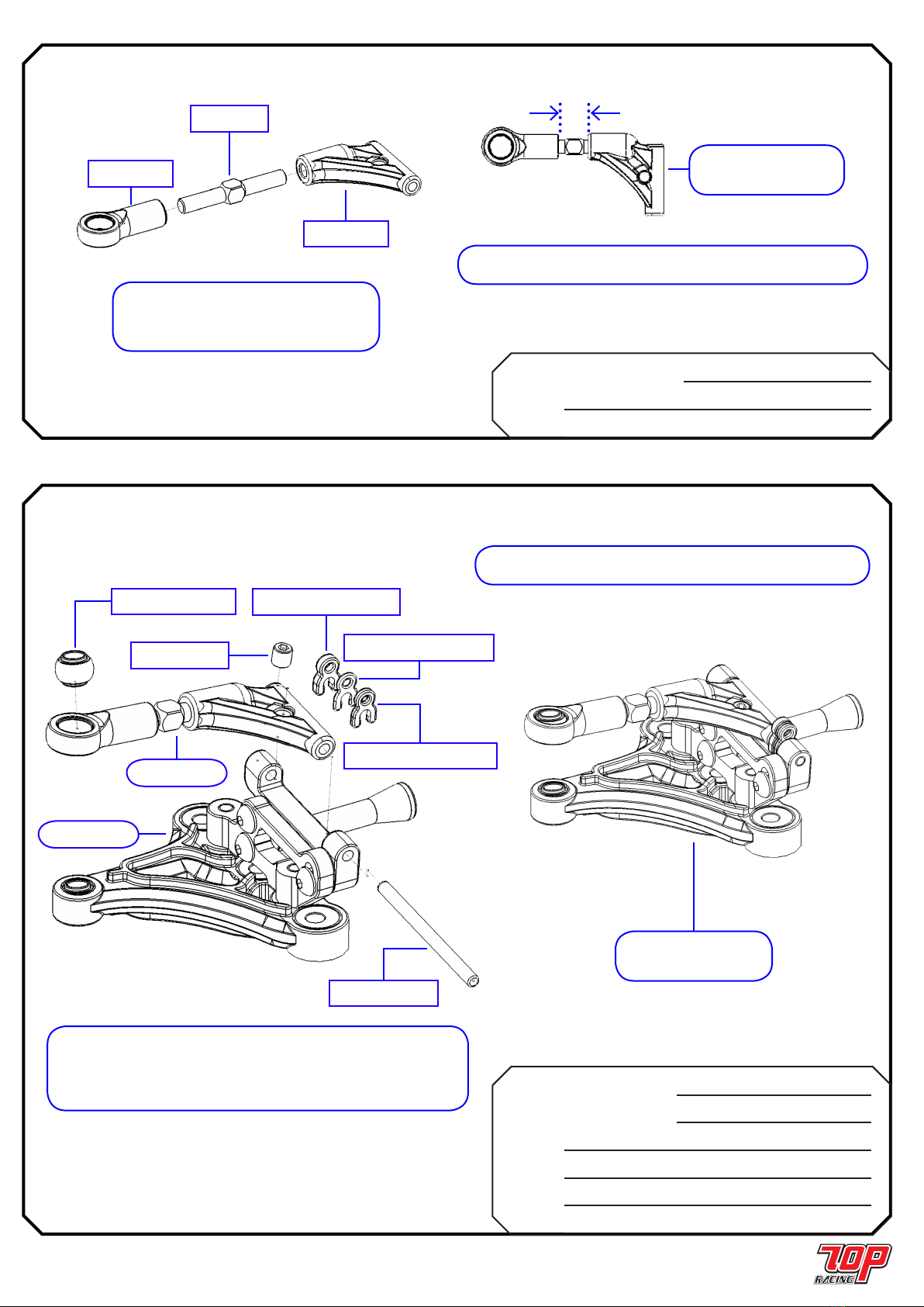
STEP 10,11 & 13の重要な注意点 / IMPORTANT NOTES FOR STEP 10, 11 & 13
注意: ピボットソケットインサートの位置付けに注意。
ピ ボットボ ー ル が 、かろうじて 回 転 す るまでピ ボットソケッ
トネジをゆっくり と締めてゆきます。ピボットボールがきつ
くなり始めたら、ピボットボール が再びかろうじて回転する
までピ ボットソケットネジ を 緩 め ます。
Note: Pay attention to the orientation of the pivot socket
insert. Tighten the pivot socket screw very slowly until
the pivot ball is barely free to rotate. If the pivot ball starts
to bind, untighten the pivot socket screw until the pivot
ball becomes barely free to rotate again.
STEP 10 から
from STEP 10
注意: リンクの位置付けに注意。リンクの両端にサイドスプリングが入る凹所があります。ピ
ボットボールがかろうじて回転 するまで両端箇所でM2x7 mmチェスヘッドネジをゆっくりと締めます。もしピ
ボットボールがきつくなり始めたら、 ピボットボールが再びかろうじて回転するまでネジを緩めます。
Note: Pay attention to the orientation of the link. There is a recess area at both ends of the link for the
side spring to fall into. Tighten the M2 x 7mm chess head screw very slowly at both ends of the link until
the pivot ball is barely free to rotate. If the pivot ball starts to bind, untighten the screw until the pivot ball
becomes barely free again.
STEP 11 から
from STEP 11
STEP 13 から
from STEP 13
注意: クロスブレースのカーボン材破損を避けるため、M3
ネジ切りを使用し事前に2つ穴 (一つのみ示しています)を切り、
その後でイモネジに捩じ込みます。その際穴の深さは 半分にして
下さい。それでないと穴が緩くなり過ぎます。
Note: To avoid breakage of the carbon material of the cross
brace, pre-tapp the 2 holes (ONLY one shown here) with an
M3 tapper before screwing in the set screws. Do it ONLY for
half the depth of the holes: otherwise the holes will become
too losse.

Page 4
PC-RMAS02 アッパーヒンジピンホルダー
Upper Hinge Pin Holder x 2
PC-RSU002RD リ アク テ ィブ ア ジ ャス タ ー
Reactive Adjuster x 2
PC-RCH013RD フロントクロスブレスチューフ
Front Cross Brace Tube x 2
PA-BM0308BK M3 x 8mm ボ タンヘッドネシ
M3 x 8mm Button Head Screw x 4
PA-BM2506BK M2.5 x 6mm ボ タンヘッドネシ
M2.5 x 6mm Button Head Screw x 2
PA-BM2508BK M2.5 x 8mm ボ タンヘッドネシ
M2.5 x 8mm Button Head Screw x 4
STEP 02
注意: Step 02はロアーフロントサスペンション右側の 組
立てを示してます。左側は同じ要領で組立てま すが、右側に
対して対称になるように行います。
Note: Step 02 shows the the right hand side of the lower
front suspension assembly. Assemble the left hand side
the same way but symmetrical to the right hand side.
STEP 02 終了
(右側のみを示してます)
STEP 02 FINISHED
(Only Right Hand Side Shown)
M3 x 8mm ボ タ ンヘッド ネシ
M3 x 8mm Button Head Screw
M2.5 x 8mm ボ タ ンヘッド ネシ
M2.5 x 8mm Button Head Screw
アッパーヒンジピンホルダー
Upper Hinge Pin Holder
STEP 01 から
from STEP 01
フロントクロスブレスチューフ
Front Cross Brace Tube
リ アク テ ィブ ア ジ ャス タ ー
Reactive Adjuster
M2.5 x 6mm ボ タ ンヘッド ネシ
M2.5 x 6mm Button Head Screw
ロアーフロントサスペンション / LOWER FRONT SUSPENSION
PC-RMAS01 フロント サスアーム
Front Suspension Arm x 2
PC-RSU003RD サスマウントインサート
Suspension Mount Insert x 6
PC-RSU010 フロントサスペンションボー ル
Front Suspension Ball x 2
STEP 01
注意: 左右ロアーサスペンションは同一に組立てます。
図のとおり、 各方向にサスマウントインサートの取付け位置
に気をつけて 下さい。
Note: The left and right lower suspension assemblies are
identical Pay attention to the orientation of the suspension
mount insert for each location as shown.
注意: 左記図のとおりロアーフロントサスペ
ンションを同一に組立て2個作成
Note: Make 2x identical lower front suspension
assemblies shown in the diagram on the left.
サスマウントインサート
Suspension Mount Insert
フロント サスアーム
Front Suspension Arm
フロントサスペンションボー ル
Front Suspension Ball
STEP 01 終了
STEP 01 FINISHED
左
LEFT
右
RIGHT
Page 5
アッパーフロントサスペンション / UPPER FRONT SUSPENSION
PC-RMAS02
アッパー A -アーム
Upper A-Arm x 2
アッパー アイレット
Upper Eyelet x 2
PC-RLK001 20mm タ イロット
20mm Tie Rod x 2
STEP 03
注意: アッパ ーフ ロントサスペ ンション を 図
のように同 一に2つ組立てます。
Note: Make 2x identical upper front suspension
assemblies shown in the diagram above
注意: 左右アッパーサスペンションは同一に組立てます。
Note: The left and right upper suspension assemblies are identical.
アッパー A -アーム
Upper A-Arm
アッパー アイレット
Upper Eyelet
20mm タ イロット
20mm Tie Rod
PC-RMCS05
アッパ ー ヒン ジ ピ ンクリップ - 1.5mm
Upper Hinge Pin Clip - 1.5mm x 2
ア ッ パ ー ヒ ン ジ ピ ン ク リップ - 1.0mm
Upper Hinge Pin Clip - 1.0mm x 2
アッパ ー ヒン ジ ピ ンクリップ - 0.5mm
Upper Hinge Pin Clip - 0.5mm x 2
PC-RSU009 アッパーアームヒンジピン
Upper Arm Hinge Pin x 2
PC-RSU010 フロントサスペンションボー ル
Front Suspension Ball x 2
PA-SS0303BK M3 x 3mm イモネシ
M3 x 3mm Set Screw x 2
STEP 04
フロントサスペンションボー ル
Front Suspension Ball
M3 x 3mm イモネシ
M3 x 3mm Set Screw
ア ッ パ ー ヒ ン ジ ピ ン ク リップ - 1.0mm
Upper Hinge Pin Clip - 1.0mm
アッパ ー ヒン ジ ピ ンクリップ - 0.5mm
Upper Hinge Pin Clip - 0.5mm
アッパ ー ヒン ジ ピ ンクリップ - 1.5mm
Upper Hinge Pin Clip - 1.5mm
アッパーアームヒンジピン
Upper Arm Hinge Pin
STEP 02 から
from STEP 02
STEP 03 から
from STEP 03
フロントサスペンション / FRONT SUSPENSION
注意: 右側サスペンションの組立の説明は上の図の通りです。右側サスペ
ンションに対称になるようにして、同様に左側サスペンションを組立てます。
Note: The instruction for making the right suspension is shown in the
above diagram. Similarly, make the left suspension assembly symmetrical
to the right suspension assembly.
注意: 左右サスペンションは対称に組立てます。
Note: The left and right suspension assemblies are symmetrical.
STEP 04 終了
(右側のみを示してます)
STEP 04 FINISHED
(Only Right Hand Side Shown)
STEP 03 終了
(右側のみを示してます)
STEP 03 FINISHED
(Only Right Hand Side Shown)
6.8mm

Page 6
フロントサスペンション(続き) / FRONT SUSPENSION (cont’d)
PC-RMAS06 ステアリングブロック
Inline Steering Block x 2
PC-RGDT01 フロントアクスル
Inline Front Axle x 2
STEP 06 (2つ作成 / Make 2)
PA-SS0303BK M3 x 3mm イモネシ
M3 x 3mm Set Screw x 2
AW-KS050RD キングピンシム - 0.5mm
King Pin Shim - 0.5mm x 2
AW-KS100RD キングピンシム - 1.0mm
King Pin Shim - 1.0mm x 2
AW-KS200RD キングピンシム - 2.0mm
King Pin Shim - 2.0mm x 2
AW-KS300RD キングピンシム - 3.0mm
King Pin Shim - 3.0mm x 2
PA-ER0020 2.0mm Eクリッフ
2.0mm E-Clip x 2
STEP 07
フロントアクスル
Inline Front Axle
ステアリングブロック
Inline Steering Block
STEP 06 終了
(右側のみを示してます)
STEP 06 FINISHED
(Only Right Hand Side Shown)
注意: 左右アッパーサスペンションは同一に組立てます。
Note: The left and right upper suspension assemblies are identical.
注意: 右側サスペンションの組立の説明は上の図の通りです。右側サス
ペンションに対称になるようにして、同様に左側サスペンションを組立てます。
Note: The instruction for making the right suspension is shown in the
above diagram. Similarly, make the left suspension assembly symmetrical
to the right suspension assembly.
STEP 07 終了
(右側のみを示してます)
STEP 07 FINISHED
(Only Right Hand Side Shown)
注意: 左右サスペンションは対称に組立てます。
Note: The left and right suspension assemblies are symmetrical.
STEP 04 から
from STEP 04
STEP 06 から
from STEP 06
STEP 05 から
from STEP 05
キングピンシム - 2.0mm
King Pin Shim - 2.0mm
M3 x 3mm イモネシ
M3 x 3mm Set Screw
キングピンシム - 0.5mm
King Pin Shim - 0.5mm
キングピンシム - 3.0mm
King Pin Shim - 3.0mm
キングピンシム - 1.0mm
King Pin Shim - 1.0mm
2.0mm Eクリッフ
2.0mm E-Clip
STEP 05 (2つ作成 / Make 2)
フロントスプリング 0.45mm x 5 コイル
Front Spring 0.45mm x 5 coils
2.0mm Eクリッフ
2.0mm E-Clip キングピン
King Pin
スプ リン グ カップ
Spring Cup
0.5mm キングピンシム
0.5mm King Pin Shim
注意: 同一のキングピンを2つ組立てます。
Note: Make 2x identical king pin assembly
STEP 05 終了
(右側のみを示してます)
STEP 05 FINISHED
(Only one assmebly Shown)
PS-PFL04550 フロントスプリング 0.45mm x 5 コイル
Front Spring 0.45mm x 5 coils x 2
PC-RGSU01 キングピン
King Pin x 2
AW-KS050RD 0.5mm キングピンシム
0.5mm King Pin Shim x 2
PA-ER0020 2.0mm Eクリッフ
2.0mm E-Clip x 2
PC-RMDS06 スプ リン グ カップ
Spring x 2

フロントサスペンション(続き) / FRONT SUSPENSION (cont’d)
STEP 08
M3 x 8mm 皿ビス
M3 x 8mm Countersunk Screw
フロントアームマウント
Front Arm Mount
フロントサスペンションアームスペーサー(2 mm)
Front Suspension Arm Spacer (2mm)
STEP 07 終了
(右側のみを示してます)
STEP 07 FINISHED
(Only Right Hand Side Shown)
PC-RSU005RD フロントサスペンションアームスペーサー(2 mm)
Front Suspension Arm Spacer (2mm) x 2
PC-RGCHS03 フロントアームマウント
Front Arm Mount x 2
PA-SC0308 M3 x 8mm 皿ビス
M3 x 8mm Countersunk Screw (Silver) x 6
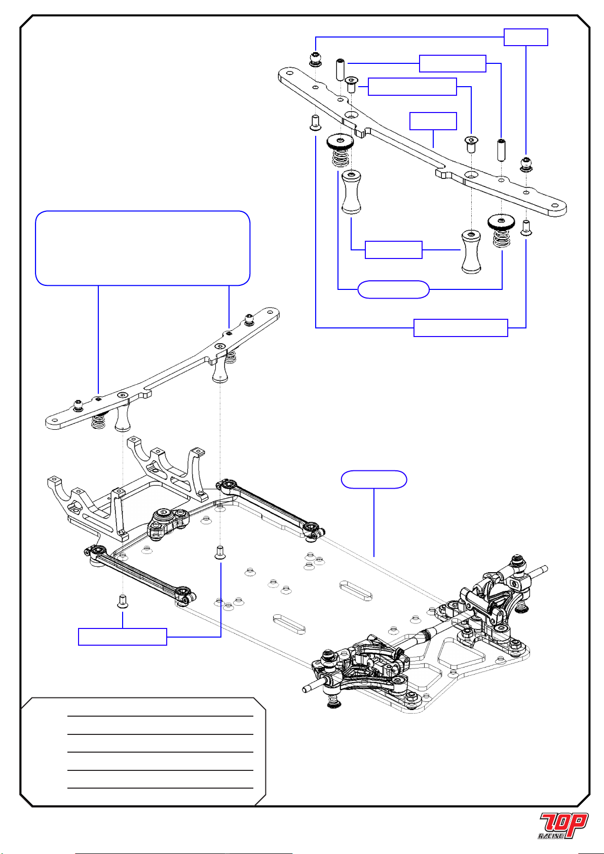
STEP 10
PC-RCHS005 ボトムプレート
Bottom Plate x 1
PC-RCH008RD モ ー タ ープレ ート
Motor Plate x 1
PC-RCH009RD マ ウ ントプ レ ー ト
Mount Plate x 1
PC-RMAS04 ボトムピ ボットソケット
Bottom Pivot Socket x 1
PC-RSU011 ピ ボットボ ー ル
Pivot Ball x 1
PC-RSU013RD
ピ ボットソケットインサ ート
Pivot Socket Insert x 1
ピ ボットソケットネシ
Pivot Socket Screw x 1
PA-CM0306BK M3 x 6mm 皿ビス
M3 x 6mm Countersunk Screw x 5
リア シャーシ / REAR CHASSIS
マ ウ ントプ レ ー ト
Mount Plate
モ ー タ ープレ ート
Motor Plate
M3 x 6mm 皿ビス
M3 x 6mm Countersunk Screw
ピ ボットボ ー ル
Pivot Ball
ボトムピ ボットソケット
Bottom Pivot Socket
ボトムプレート
Bottom Plate
ピ ボットソケットインサ ート
Pivot Socket Insert
ピ ボットソケットネシ
Pivot Socket Screw 注意: ピボットボールの動きがしぶくならない程度にピボットスクリュ
ーネジを締めます。
Note: Tighten the Pivot Socket Screw as far as it does not bind the free
movement of the Pivot Ball.
STEP 08 から
from STEP 08
STEP 09
PA-FN00M3 M3 ナット
M3 Nut x 6
PC-RGCHS01 シャーシ
Chassis x 1
PC-RCH014
フロントクロスブレースインサート
Front Cross Brace Insert x 1
ダンパーOリング 30度
Damper O-Ring 30-deg x 1
PA-CM0308BK M3 x 8mm 皿ビス
M3 x 8mm Countersunk Screw x 6
注意: 左右サスペンション組立ては、 図のよ
うに対称的に行います。
Note: Assemble the right and left
suspension assemblies as shown in the
gure, in a symmetrical way.
メインシャーシ
Main Chassis
M3 ナット
M3 Nut
M3 ナット
M3 Nut
フロントクロスブレースインサート
Front Cross Brace Insert
M3 x 8mm 皿ビス
M3 x 8mm Countersunk Screw
ダンパーOリング 30度
Damper O-Ring 30-deg
Page 7

Page 8
PC-RMDS04 リンク
Link x 2
PC-RSU011 ピ ボットボ ー ル
Pivot Ball x 4
PA-FN00M3 M3 ナット
M3 Nut x 2
PA-SCM207BK M2 x 7 mm チェスヘッドネシ
M2 x 7mm Chess Head Screw x 4
PA-CM0306BK M3 x 6mm 皿ビス
M3 x 6mm Countersunk Screw x 4
PA-CM0308BK M3 x 8mm 皿ビス
M3 x 8mm Countersunk Screw x 2
STEP 11
M3 x 8mm 皿ビス
M3 x 8mm Countersunk Screw
リンク
Link
リンク
Link
M3 x 6mm 皿ビス
M3 x 6mm Countersunk Screw
M3 x 6mm 皿ビス
M3 x 6mm Countersunk Screw
M2 x 7 mm チェスヘッドネシ
M2 x 7mm Chess Head Screw
M2 x 7 mm チェスヘッドネシ
M2 x 7mm Chess Head Screw
ピ ボットボ ー ル
Pivot Ball
M3 ナット
M3 Nut
ピ ボットボ ー ル
Pivot Ball
STEP 10 から
from STEP 10
STEP 09 から
from STEP 09
注意: 側面図
Note: Side View
リアサイドサスペンション / REAR SIDE SUSPENSION
STEP 12 (2つ作成 / Make 2)
PC-RMBS04 ス プ リン グ ア ジ ャス タ ー
Spring Adjuster x 2
PS-PS05560 サイドスプリング 0.55mm x 6コイル
Side Spring 0.55mm x 6 coils x 2
サイドスプリング 0.55mm x 6コイル
Side Spring 0.55mm x 6 coils
ス プ リン グ ア ジ ャス タ ー
Spring Adjuster
STEP 12 終了
STEP 12 FINISHED
ピ ボットボ ー ル
Pivot Ball
ピ ボットボ ー ル
Pivot Ball
ボ ー ルスタット
Ball Stud
クロス ブレース
Cross Brace
M3 x 6mm 皿ビス
M3 x 6mm Countersunk Screw
M3 x 10mm イモネシ
M3 x 10mm Set Screw
Page 9
STEP 13
PC-RGCHS02 クロス ブレース
Cross Brace x 1
PC-RCH015RD 18mm スタンドオフ
18mm Standoff x 2
AW-HBS004H ボ ー ルスタット
Ball Stud x 2
PA-CM0306BK M3 x 6mm 皿ビス
M3 x 6mm Countersunk Screw x 4
PA-CM2506BK M2.5 x 6mm 皿ビス
M2.5 x 6mm Countersunk Screw x 2
PA-SS0310BK M3 x 10mm イモネシ
M3 x 10mm Set Screw x 2
STEP 12 から
from STEP 12
18mm スタンドオフ
18mm Standoff
M2.5 x 6mm 皿ビス
M2.5 x 6mm Countersunk Screw
M3 x 6mm 皿ビス
M3 x 6mm Countersunk Screw
STEP 11 から
from STEP 11
注意: カーボン材の破損を防ぐために、2箇所の穴を
M3ねじ切りで事前処理します。その際穴の半分の深さだけ
にして下さい。そうでないと、穴が緩くなり過ぎます。
Note: To avoid breakage of the carbon material, pre-tapp
the 2 holes with an M3 tapper before screwing in the set
screws. Do it ONLY half the depth of the holes; otherwise
the holes will become too loose.

Page 10
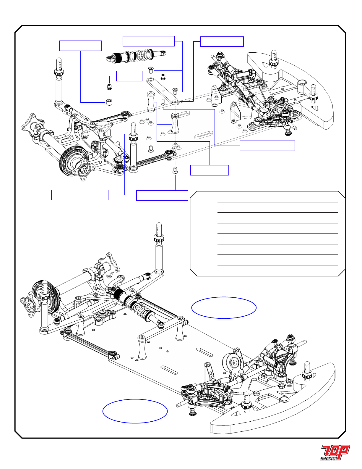
リアサイドサスペンション(続く) / REAR SIDE SUSPENSION (cont’d)
STEP 14
PC-RMBS01 ボ ー ル カップ - 8.75mm
Ball Cup - 8.75mm x 4
PC-RCHS006 ショックマウント
Shock Mount x 1
PC-RCH011RD ダ ンパ ー チュ ーフ
Damper Tube x 2
PC-RCH012 ダ ンパ ー ロット
Damper Rod x 2
AW-HBS004H ボ ー ルスタット
Ball Stud x 3
PA-CM2506BK M2.5 x 6mm 皿ビス
M2.5 x 6mm Countersunk Screw x 5
PA-SS0308BK M3 x 8mm イモネジ
M3 x 8mm Set Screw x 4
注意: 2つ作成
Note: Make 2
STEP 13 から
from STEP 13
M2.5 x 6mm 皿ビス
M2.5 x 6mm Countersunk Screw
ダ ン パ ー チ ュ ーフ
Damper Tube
ダ ンパ ー ロット
Damper Rod
ボ ー ル カップ - 8.75mm
Ball Cup - 8.75mm
M3 x 8mm イモネジ
M3 x 8mm Set Screw
ショックマウント
Shock Mount
ボ ー ルスタット
Ball Stud
ボ ー ルスタット
Ball Stud
M2.5 x 6mm 皿ビス
M2.5 x 6mm Countersunk Screw
M2.5 x 6mm 皿ビス
M2.5 x 6mm Countersunk Screw

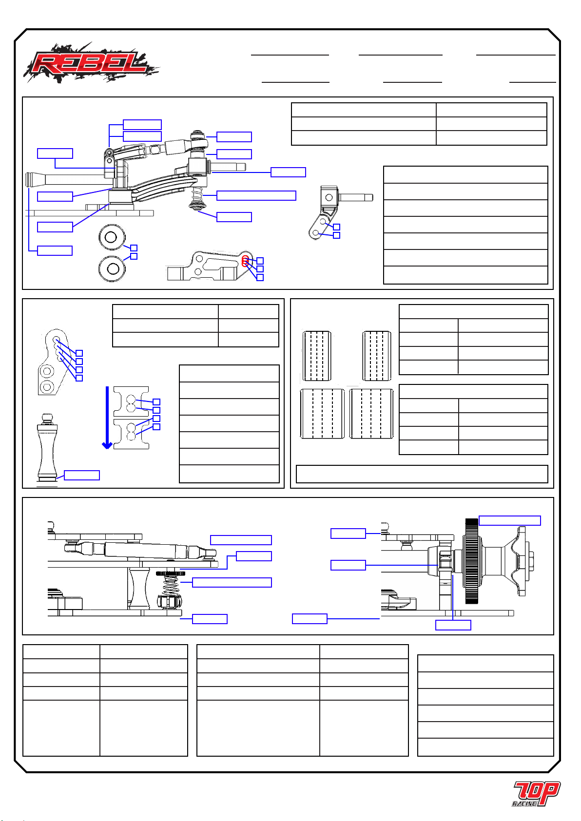
Page 11
リアセンターサスペンション / REAR CENTER SUSPENSION
STEP 15
PC-RMBS02 ボ ー ル カップ - 16 mm
Ball Cup - 16mm x 1
PC-RMBS03 シ ョック キ ャッフ
Shock Cap x 1
PC-RSH001 ショックボディー
Shock Body x 1
PC-RSH002RD ショックキャップ リテ ー ナ ー
Shock Cap Retainer x 1
PC-RSH003RD ショックガ イドリテ ー ナ ー
Shock Guide Retainer x 1
PC-RSH004RD スプリングリテ ーナー
Shock Spring Retainer x 1
PC-RSH005 ショックスプリングリテー ナ ー
Shock Spring Adjuster x 1
PC-RSH006 ショックシャフト
Shock Shaft x 1
PC-RSH007 ショックピストン
Shock Piston x 1
PC-RSH008 ショックガ イト
Shock Guide x 1
PC-RSH009 ショックブラダー
Shock Bladder x 1
PP-012200 ショック Oリンク
Shock O-Ring x 1
PS-PC11080 センターショックスプリンク 1.1mm X 8 coils
Center Shock Spring 1.1mm X 8 coils x 1
PA-ER0015 1.5mm Eクリッフ
1.5mm E-Clip x 2
PA-SS0303BK M3 x 3mm イモネシ
M3 x 3mm Set Screw x 1
注意: 45wt ショッ
ク オイル (別売) 使用
Note: Use 45wt shock
Oil (sold separately)
ショックシャフト
Shock Shaft
1.5mm Eクリッフ
1.5mm E-Clip
ショックピストン
Shock Piston
ショックボディー
Shock Body
ショックスプリングリテー ナ ー
Shock Spring Adjuster
ショック Oリンク
Shock O-Ring
ショックガ イト
Shock Guide
ショックガ イドリテ ー ナ ー
Shock Guide Retainer
ショックキャップ リテ ー ナ ー
Shock Cap Retainer
シ ョック キ ャッフ
Shock Cap
ショックブラダー
Shock Bladder
センターショックスプリンク 1.1mm X 8 coils
Center Shock Spring 1.1mm X 8 coils
ショックスプリングリテー ナ ー
Shock Spring Adjuster
ボ ー ル カップ - 16 mm
Ball Cup - 16mm
M3 x 3mm イモネシ
M3 x 3mm Set Screw
STEP 15 終了
STEP 15 FINISHED
PC-RMDS02 アンテナ&ショックマウント
Antenna & Shock Mount x 1
PC-RCHS002 ショックタワー
Shock Tower x 1
AW-HBS004H ボ ー ルスタット
Ball Stud x 1
PA-BM2504BK M2.5 x 4mm ボ タンヘッドネシ
M2.5 x 4mm Button Head Screw x 1
PA-CM2506BK M2.5 x 6mm 皿ビス
M2.5 x 6mm Countersunk Screw x 2
STEP 16
アンテナ&ショックマウント
Antenna & Shock Mount
ボ ー ルスタット
Ball Stud
ショックタワー
Shock Tower
M2.5 x 4mm ボ タ ンヘッド ネシ
M2.5 x 4mm Button Head Screw
M2.5 x 6mm 皿ビス
M2.5 x 6mm Countersunk Screw
STEP 16 終了
STEP 16 FINISHED
Page 12
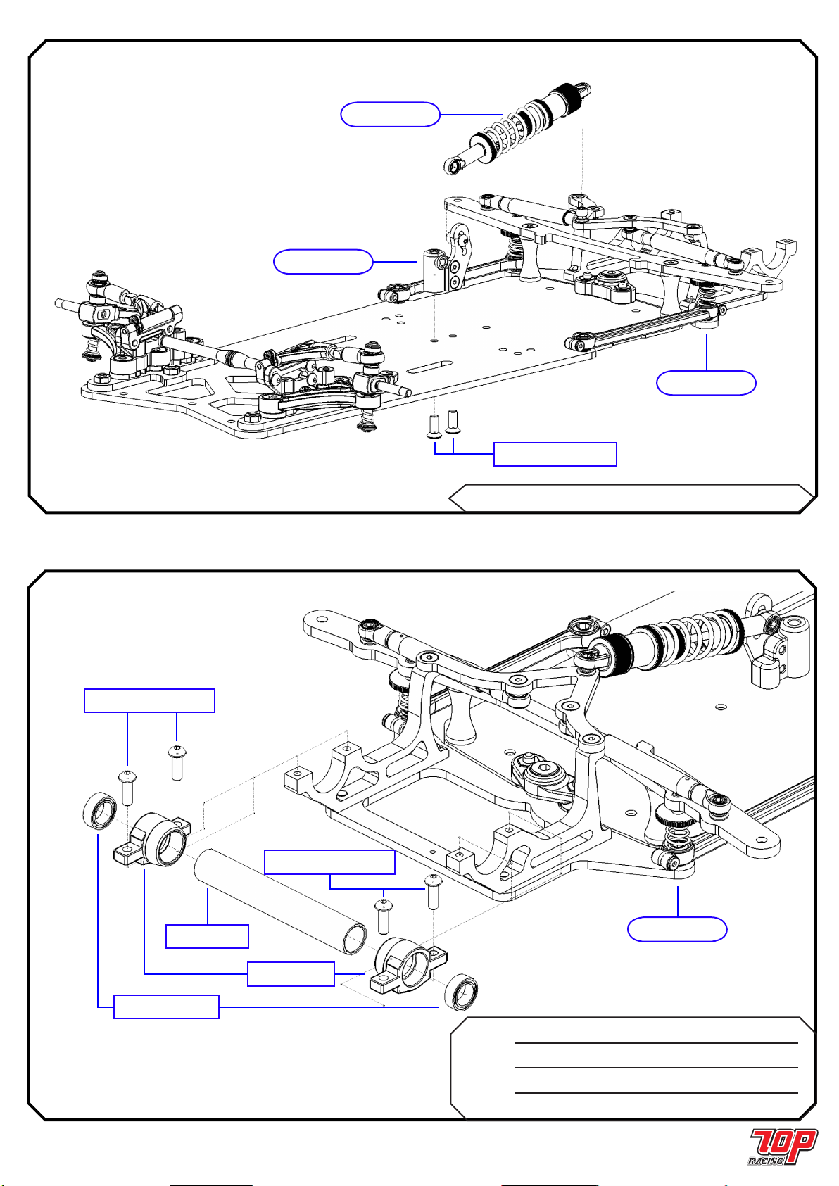
リアセンターサスペンション (続き) / REAR CENTER SUSPENSION (cont’d)
STEP 17
PC-RMAS07 ベアリング キャリア B
Bearing Carrier B x 2
PC-RCH010RD ア ジ ャス タ ー チ ュ ーフ
Adjuster Tube x 1
RA-SB0168 1/4 x 3/8 ボールベアリンク
1/4 x 3/8 Ball Bearing x 2
PA-BM2508BK M2.5 x 8mm ボ タンヘッドネシ
M2.5 x 8mm Button Head Screw x 4
リアアクスルアセンブリー / REAR AXLE ASSEMBLY
STEP 18
M3 x 8mm 皿ビス
M3 x 8mm Countersunk Screw
STEP 14 から
from STEP 14
STEP 15 から
from STEP 15
STEP 16 から
from STEP 16
STEP 17 から
from STEP 17
ベアリング キャリア B
Bearing Carrier B
M2.5 x 8mm ボ タ ンヘッド ネシ
M2.5 x 8mm Button Head Screw
1/4 x 3/8 ボールベアリンク
1/4 x 3/8 Ball Bearing
ア ジ ャス タ ー チ ュ ーフ
Adjuster Tube
M2.5 x 8mm ボ タ ンヘッド ネシ
M2.5 x 8mm Button Head Screw
PA-CM0308BK M3 x 8mm 皿ビス
M3 x 8mm Countersunk Screw x 2
Page 13
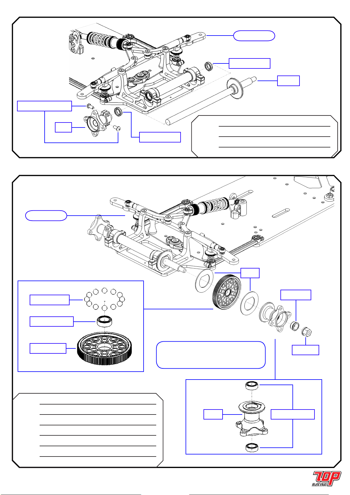
リアアクスルアセンブリー (続き) / REAR AXLE ASSEMBLY (cont’d)
STEP 19
PC-RDT001BK リアアクスル
Rear Axle x 1
PC-RGDT02RD 左ハフ
Left Hub x 1
AW-AS200RD 2mm アクスルスペーサー
2mm Axle Spacer x 2
PA-BM2506BK M2.5 x 6mm ボ タンヘッドネシ
M2.5 x 6mm Button Head Screw x 2
PC-RMCS04 デフナット
Differential Nut x 1
SG-K64100 スパーギア 64P 100T
Spur Gear 64P 100T x 1
PC-RGDT03RD 右ハフ
Right Hub x 1
PC-RDT003RD デフカラー
Differential Collar x 1
PA-DR0001 デフリンク
Diff. Ring x 2
PO-CDB112BK セラミックデフバー 1/8”
Ceramic Diff. Ball 1/8” x 12
PA-SB0168 1/4 x 3/8 ボールベアリンク
1/4 x 3/8 Ball Bearing x 3
リア デファレンシャル / REAR DIFFERENTIAL
STEP 20
STEP 18 から
from STEP 18
リアアクスル
Rear Axle
左ハフ
Left Hub
M2.5 x 6mm ボ タ ンヘッド ネシ
M2.5 x 6mm Button Head Screw
2mm アクスルスペーサー
2mm Axle Spacer
スパーギア 64P 100T
Spur Gear 64P 100T
セラミックデフバ ー 1/8”
Ceramic Diff. Ball 1/8”
1/4 x 3/8 ボールベアリンク
1/4 x 3/8 Ball Bearing
右ハフ
Right Hub
1/4 x 3/8 ボールベアリンク
1/4 x 3/8 Ball Bearing
STEP 19 から
from STEP 19
デフナット
Differential Nut
デフカラー
Differential Collar
デフリンク
Diff. Ring
注意: 路面状況に合わせてデフのきつさを デフ
アジャストナットで調整
Note: Use the differential adjust nut to adjust the
tightness of the diff. according to track condition.
2mm アクスルスペーサー
2mm Axle Spacer

Page 14
ステアリングアセンブリー / STEERING ASSEMBLY
STEP 21
PC-RMBS02 ボ ー ル カップ - 16mm
Ball Cup - 16mm x 4
SS-KM01BK サーボセーバー - 中サイス
Servo Saver - Mid Size x 1
PC-RLK003 タイロッド - 45mm
Tie Rod - 45mm x 2
AW-HBS004H ボ ー ルスタット
Ball Stud x 4
PA-BM2504BK M2.5 x 4mm ボ タンヘッドネシ
M2.5 x 4mm Button Head Screw x 2
PA-BM2506BK M2.5 x 6mm ボ タンヘッドネシ
M2.5 x 6mm Button Head Screw x 2
STEP 20 から
from STEP 20
ボ ー ルスタット
Ball Stud
M2.5 x 6mm ボ タ ンヘッド ネシ
M2.5 x 6mm Button Head Screw
M2.5 x 6mm ボ タ ンヘッド ネシ
M2.5 x 6mm Button Head Screw
ボ ー ルスタット
Ball Stud
サーボセーバー - 中サイス
Servo Saver - Mid Size
M2.5 x 4mm ボ タ ンヘッド ネシ
M2.5 x 4mm Button Head Screw
ボ ー ル カップ - 16mm
Ball Cup - 16mm
タイロッド - 45mm
Tie Rod - 45mm
32mm
注意: 左右対称に同一の タ
イロッドを2つ作成。
Note: Make 2 identical tie-rods
symmetrical to each other.

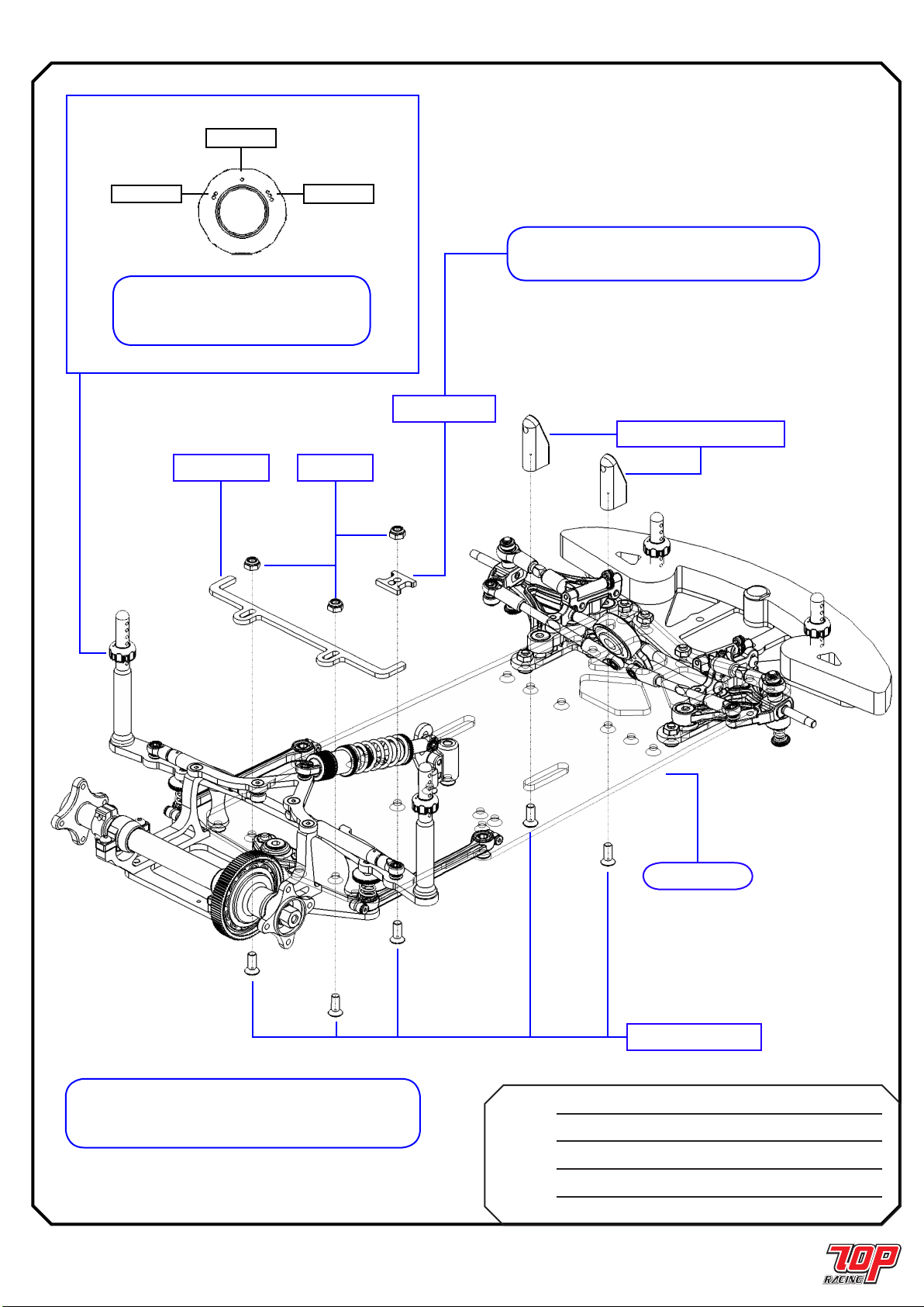
Page 15
バンパー & ボディポスト / BUMPER & BODY POSTS
STEP 22
PC-RGCHS05 バンパー
Bumper x 1
PA-FN00M3 M3 ナット
M3 Nut x 3
PC-PMQS03
ボディポスト
Body Post x 2
ボディポスト
Tall Body Post x 2
バンパー - ホールドダウン
Bumper - Hold Down x 1
ボ デ ィポ ス トア ジ ャス タ ー
Body Post Adjuster x 4
PC-RCH019 ボディポストロ ールピン
Body Post Roll Pin x 4
PC-RGCH08 バ ンパ ーフォ ー ム
Bumper Foam x 1
PA-BM0306BK M3 x 6mm ボ タンヘッドネシ
M3 x 6mm Button Head Screw x 3
PA-CM0308BK M3 x 8mm 皿ビス
M3 x 8mm Countersunk Screw x 5
M3 x 8mm 皿ビス
M3 x 8mm Countersunk Screw
M3 x 8mm 皿ビス
M3 x 8mm Countersunk Screw
M3 x 8mm 皿ビス
M3 x 8mm Countersunk Screw
バ ンパ ーフォ ー ム
Bumper Foam
バンパー - ホールドダウン
Bumper - Hold Down
M3 ナット
M3 Nut
ボ デ ィポ ス トア ジ ャス タ ー
Body Post Adjuster
ボ デ ィポ ストア ジ ャス タ ー
Body Post Adjuster
ボディポストロ ールピン
Body Post Roll Pin
ボディポストロ ールピン
Body Post Roll Pin
バンパー
Bumper
ボディポスト
Tall Body Post
ボディポスト
Body Post
STEP 21 から
from STEP 21
M3 x 6mm ボ タ ンヘッド ネシ
M3 x 6mm Button Head Screw
Page 16
1セルバッテリーガイド、サーボマウント&ホイル /
ONE CELL BATTERY GUIDE, SERVO MOUNT & WHEELS
STEP 23
PC-RMDS03 バッテリーロケーター
Battery Locator x 1
PC-RMDS05 サーボマウント-小型サーボ-アップライト
Servo Mount - Small Servo - Upright x 2
PC-RCHS001 バッテリーポジショナー
Battery Positioner x 1
PA-LN00M3 M3 ロックナット
M3 Lock Nut x 3
PA-CM0308BK M3 x 8mm 皿ビス
M3 x 8mm Countersunk Screw x 5
注意: バッテリーポジショナーの位置付けの注意
Note: Please refer to the orientation of the battery
positioner in the instruction manual
注意: 2セル使用の場合、STEP 26 2セルバッテリー ガイ
ド&リポショックマウント組立てを参照
Note: For 2-Cell application, to STEP26 for the 2-Cell Battery
Guide & Lipo Shock Mount Assembly.
STEP 22 から
from STEP 22
サーボマウント-小型サーボ-アップライト
Servo Mount - Small Servo - Upright
バッテリーロケーター
Battery Locator
M3 x 8mm 皿ビス
M3 x 8mm Countersunk Screw
バッテリーポジショナー
Battery Positioner
M3 ロックナット
M3 Lock Nut
注意: 高さ調整では、ボディポスト
の方向づけに注意
Note: Pay attention to the orientation of the
body post adjuster for height adjustment.
Low
High
Med

Page 17
完成 / FINISH UP
STEP 25
REBEL 10
走行
の用意が整いました。
REBEL 10
IS READY
TO BE RUN
PA-SB025F 1/8 x 5/16 ボールベアリンク
1/8 x 5/16 Ball Bearing Flanged x 4
PA-LN00M3 M3 ロックナット
M3 Lock Nut x 1
AW-KS100RD キングピンシム - 1.0mm
King Pin Shim - 1.0mm x 2
PA-BM2508BK M2.5 x 8mm ボ タンヘッドネシ
M2.5 x 8mm Button Head Screw x 8
STEP 24
M2.5 x 8mm ボ タ ンヘッド ネシ
M2.5 x 8mm Button Head Screw
1/8 x 5/16 ボールベアリンク
1/8 x 5/16 Ball Bearing
1/8 x 5/16 ボールベアリンク
1/8 x 5/16 Ball Bearing Flanged
キングピンシム - 1.0mm
King Pin Shim - 1.0mm
STEP 23 から
from STEP 23
注意: ホイルの選択によりますが、シム入れ微調整はシャフトにそったホイ
ルの遊びを抑え るためです。シム入過ぎるとホイル回転がしぶくなる結果とな
ります。ホイルは別売 りです。
Note: Depending on the wheel chosen, ne-tune the shimming to minimize
play of the wheel along the shaft. Too much shimming would result in
binding of wheel rotation. Wheels are sold separately.
2セルリポ スタンドオフ
2 Cells Lipo Standoff
ボールスタッドスペーサー
Ball Stud Spacer
2 セルリポショックマウント
2 Cells Lipo Shock Mount
M3 x 6mm 皿ビス
M3 x 6mm Countersunk Screw
M2.5 x 6mm 皿ビス
M2.5 x 6mm Countersunk Screw
M2.5 x 12mm 皿ビス
M2.5 x 12mm Countersunk Screw
M3 x 8mm 皿ビス
M3 x 8mm Countersunk Screw
ボ ー ルスタッド
Ball Stud
REBEL 10
走行
の用意が整いました。
REBEL 10
IS READY
TO BE RUN
Page 18
STEP 26
2セルバッテリーガイド&リポショックマウント組立て /
TWO CELL BATTERY GUIDE & LIPO SHOCK MOUNT Assembly
AW-HBS004H ボ ー ルスタッド
Ball Stud x 1
AW-S2650RD ボールスタッドスペーサー
Ball Stud Spacer x 1
PC-RGCHS04 2 セルリポショックマウント
2 Cells Lipo Shock Mount x 1
PC-RGCH07RD 2セルリポ スタンドオフ
2 Cells Lipo Standoff x 1
PA-CM2506BK M2.5 x 6mm 皿ビス
M2.5 x 6mm Countersunk Screw x 1
PA-CM2512BK M2.5 x 12mm 皿ビス
M2.5 x 12mm Countersunk Screw x 1
PA-CM0306BK M3 x 6mm 皿ビス
M3 x 6mm Countersunk Screw x 2
PA-CM0308BK M3 x 8mm 皿ビス
M3 x 8mm Countersunk Screw x 2

Page 19
セッティング記録 / SETUP RECORD
名前:
Name:
日付:
Date:
トラック:
Track:
国籍:
Country:
条件:
Condition:
温度:
Temperature:
10
アッパーアーム マウント /
UPPER ARM MOUNTS
Upper
Middle
xLower
サ ー ボ セ ー バ ー セット /
SERVO SAVER SET
x
2
1
センター ショック ポジション /
CENTER SHOCK POSITION
4
x3
2
1
4
3
2
x1
バッテリー ポジショナー /
BATTERY POSITIONER
FRONT
フロントエント/ FRONT END:
ライドハイト / RIDE HEIGHT 4.5 mm
キャンバ ーアングル / CAMBER ANGLE -1.5 deg.
キングピン潤滑油 / KING PIN LUBE 20,000 cst
1 Cell Li-Po
センター / CENTER: タイヤ / TIRES:
メモ / NOTES:
ショックスプリンク / SHOCK SPRING 1.1m x 8 (Copper)
ショックオイル / SHOCK OIL 45 wt.
フォームインサート / FOAM INSERT n/a
メモ / NOTES:
フロントタイヤ / FRONT TIRES
タイヤ / TIRE Xceed Hard
直径 / DIAMETER 52 mm
ホイル / WHEEL std
添加剤 / ADDITIVE Paragon Ground Effect
リアタイヤ / REAR TIRES
タイヤ / TIRE Xceed Soft
直径 / DIAMETER 53 mm
ホイル / WHEEL std
添加剤 / ADDITIVE Paragon Ground Effect
メモ / NOTES:
ボディー / BODY SHELLS
モーター / MOTOR
ギア / GEAR
バッテリー / BATTERY
ESC セッティンク /
ESC SETTINGS
ステアリングトラベル / STEERING TRAVEL
ステアリング感度 / STEERING EXPO
スロットル感度 / THROTTLE EXPO
ブレーキ エンドポイント / BRAKE E.P.
メモ / NOTES
メモ NOTES:
2.5 mm
4 mm
F 0 mm
R 3 mm
キャスター / CASTER
O リンク / O-RING
Wide
xNarrow
サスペンション マウントインサート /
SUSUPENSION MOUNT INSERT
L 0.45 x 5.5 (Silver)
フロントスプリンク /
FRONT SPRING
30 deg
0 mm
1 mm
0 mm
0 mm
2 mm
12 pcs
5 mm
ライドハ イト: ボトムプレ ートの 後
部/ RIDE HEIGHT: REAR OF
BOTTOM PLATE
リアエンド / REAR END:
5.2 mm
0.55mm x 6 (Copper)
2 mm
サイドスプリンク / SIDE SPRING
ライドハイト:ボトムプレート側 /
RIDE HEIGHT: SIDE OF
BOTTOM PLATE
20,000 cst
ダンパー チューフ / DAMPER TUBES
デフボール / Diff. Balls
0 mm
0 mm
2 セルバッテリーマウント /
2Cell Battery Mount
0.5 mm
mm
xxx
xxxx xxxx
xxx
Medium 20 C
Page 20
セッティング記録 / SETUP RECORD
名前:
Name:
日付:
Date:
トラック:
Track:
国籍:
Country:
条件:
Condition:
温度:
Temperature:
10
アッパーアーム マウント /
UPPER ARM MOUNTS
Upper
Middle
Lower
サ ー ボ セ ー バ ー セット /
SERVO SAVER SET
2
1
センター ショック ポジション /
CENTER SHOCK POSITION
4
3
2
1
4
3
2
1
バッテリー ポジショナー /
BATTERY POSITIONER
FRONT
フロントエント/ FRONT END:
ライドハイト / RIDE HEIGHT mm
キャンバ ーアングル / CAMBER ANGLE deg.
キングピン潤滑油 / KING PIN LUBE
センター / CENTER: タイヤ / TIRES:
メモ / NOTES:
ショックスプリンク / SHOCK SPRING
ショックオイル / SHOCK OIL
フォームインサート / FOAM INSERT
メモ / NOTES:
フロントタイヤ / FRONT TIRES
タイヤ / TIRE
直径 / DIAMETER mm
ホイル / WHEEL
添加剤 / ADDITIVE
リアタイヤ / REAR TIRES
タイヤ / TIRE
直径 / DIAMETER mm
ホイル / WHEEL
添加剤 / ADDITIVE
メモ / NOTES:
ボディー / BODY SHELLS
モーター / MOTOR
ギア / GEAR
バッテリー / BATTERY
ESC セッティンク /
ESC SETTINGS
ステアリングトラベル / STEERING TRAVEL
ステアリング感度 / STEERING EXPO
スロットル感度 / THROTTLE EXPO
ブレーキ エンドポイント / BRAKE E.P.
メモ / NOTES
メモ NOTES:
mm
mm
F mm
R mm
キャスター / CASTER
O リンク / O-RING
Wide
Narrow
サスペンション マウントインサート /
SUSUPENSION MOUNT INSERT
フロントスプリンク /
FRONT SPRING
deg
mm
mm
mm
mm
mm
mm
ライドハ イト: ボトムプレ ートの 後
部/ RIDE HEIGHT: REAR OF
BOTTOM PLATE
リアエンド / REAR END:
mm
mm
サイドスプリンク / SIDE SPRING
ライドハイト:ボトムプレート側 /
RIDE HEIGHT: SIDE OF
BOTTOM PLATE
ダンパー チューフ / DAMPER TUBES
デフボール / Diff. Balls
mm
mm
2 セルバッテリーマウント /
2Cell Battery Mount
mm
mm
Table of contents
Other TOP racing Motorized Toy Car manuals

TOP racing
TOP racing Rebel 12 User manual

TOP racing
TOP racing PHOTON User manual

TOP racing
TOP racing Sabre S4 User manual

TOP racing
TOP racing Sabre S4 User manual

TOP racing
TOP racing Sabre 4WD Mini S-MB01 User manual

TOP racing
TOP racing Rebel R-F01 User manual

TOP racing
TOP racing Photon EX User manual

TOP racing
TOP racing Rebel F1X User manual


