4
www.topvehicletech.com
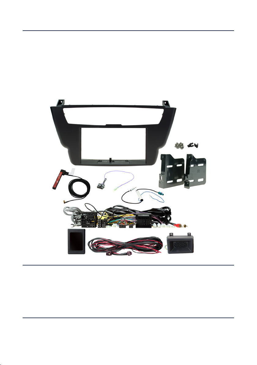
FITTING GUIDE
STEREO INSTALLATION
FASCIA PLATE SET-UP
16. Aach the addional wiring on the harness to the back of the stereo:
Pink - Speed Pulse Brown - Mute Purple - Reverse Gear Green - Park Brake
17. When all the above wires (and any addional accessories) have been connected, nally make the
connecons between the stereo and the vehicles pre-exisng connectors.
8. Connect the bullet connector from the stereo patch lead to the ‘steering wheel remote input’ on the
back of the new stereo.
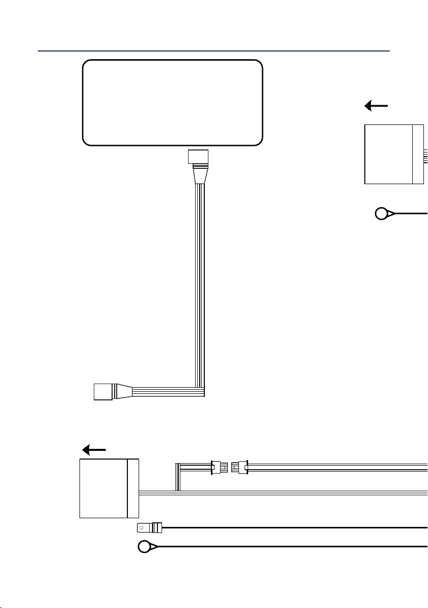
14. Connect the DAB antenna’s SMB connector to the back of the new stereo.
15. Aach the antenna adapter to the vehicles pre-exisng connecon and the back of new stereo.
7. Take the steering wheel control interface in hand and connect both the 12-way stereo patch lead and
the 14-way steering wheel harness connectors to the corresponding sides.
9. Connect the female molex on the harness to the male molex on the data extension cable.
4. When happy with the alignment, and the “Stereo Installaon” process is complete, screw the stereo
into the dashboard using the pre-exisng screws. Then re-connect any wiring and install the new fascia
over the stereo.
1. Take the climate control panel and relocate the climate control buons out and into the new fascia.
Ensure when placing that the middle clip is lined up correctly for the perfect t.
2. Aach the brackets to the new stereo using the screws within the kit. With the brackets aached, oer
the whole unit to the back of the fascia and test t within the vehicle to gauge the correct depth.
3. If the OEM panel has an LED located above the ashtray, this can be relocated into the housing provided
on the new fascia.
1. Start by aaching the LVDS extension to the display, this can then be put back in place. Then route the
rest of the LVDS cable through the glovebox and then toward the rear of vehicle.
2. You will also need to extend the following wires to the rear of the vehicle: Yellow 12V Permanent, Black
Data Extension, Female Quadlock connector (with male molex & ground terminal).
4. With the wires routed, you will need to connect the yellow 12V permanent wire to a source of 12 volt in
the rear of vehicle i.e. the fuse board or direct to baery.
REAR STEREO CONNECTIONS
3. Take the OEM stereo and re-locate it to a suitable posion in the rear of the vehicle i.e. by the amplier.
5. Connect the data extension cable to the molex connector situated on the female Quadlock connector.
At this point the ground terminal on the Quadlock connector must be aached to a non-live element.
6. Connect the LVDS connector and Quadlock connector to the OEM unit. This can then be tucked away.
FRONT STEREO CONNECTIONS
10. Connect the 2 pin connector on the harness to the speaker box.
13. Connect the ground terminal to a non-live element within the dash cavity.
11. Connect the Red & White RCA connectors on the harness to the back of the stereo.
12. Take the Amplier Interface that comes with the kit and aach both the 8 pin connector from the
harness as well as the vehicles pre-exisng bre connecon.