Nomenclature
LS-B2 Operator’s Manual
2
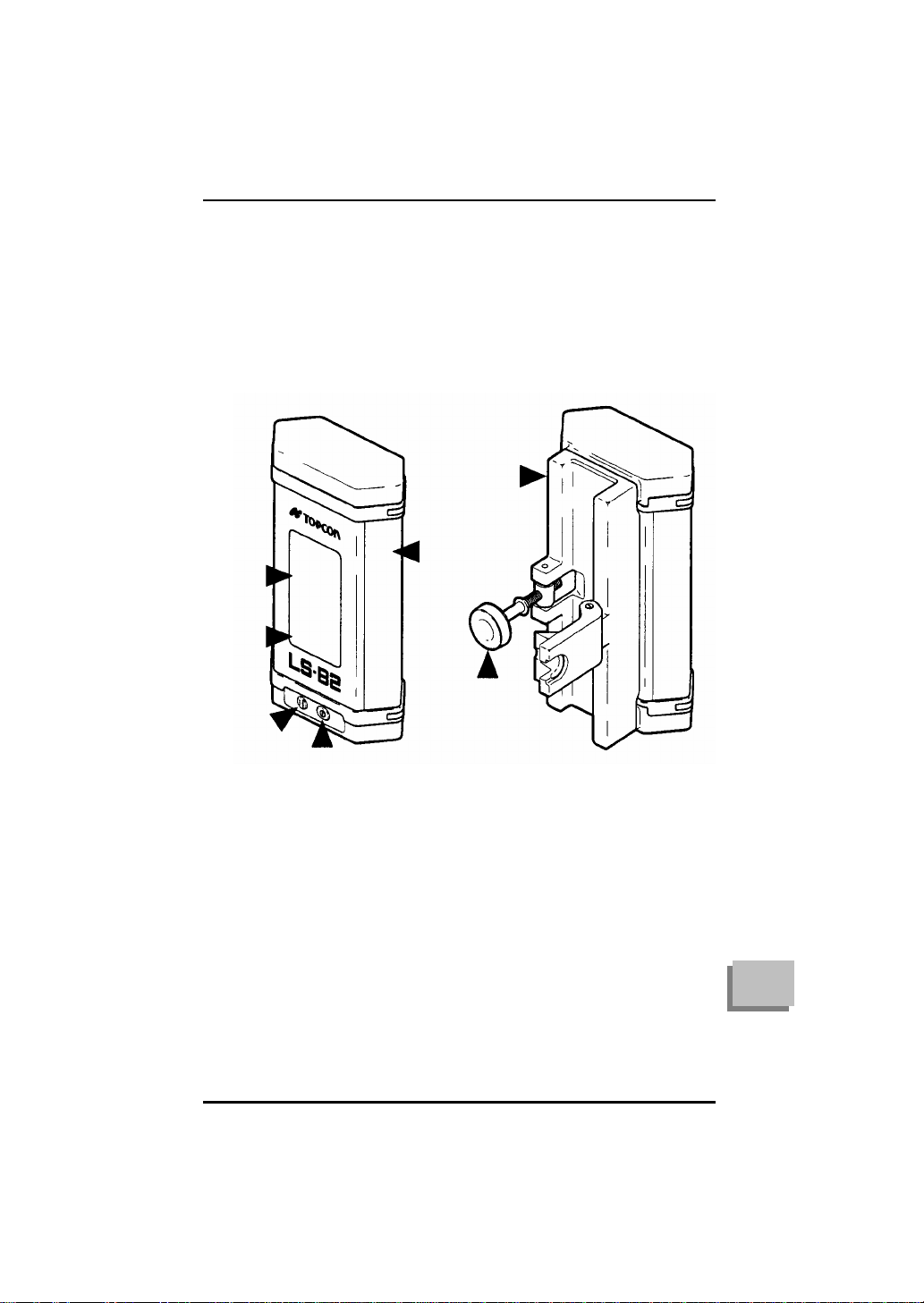
S-B2 Laser Sensor
Introduction
Thank you very much for purchasing this product from Topcon. In
order for it to serve you long and well, we ask that you read and
carefully follow the instructions contained in this manual. If you
have any questions, please contact your local authorized Topcon
dealer for assistance.
Topcon’s LS-B2 is a machine mounted laser sensor. Used in
conjunction with a rotating laser elevation reference, the LS-B2
helps operators get to grade quickly and accurately.
In manual control, the LS-B2 senses the position of a rotating laser
reference and flashes a clearly visible raise, lower, or on-grade
signal to the operator. The operator then corrects the position of the
cutting edge according to the signal. In automatic control, the LS-
B2 sends the signals directly to the machine’s hydraulics which
make the correction automatically.
The LS-B2 transfers easily from machine to machine and offers the
choice of on-board batteries or machine battery powered operation.
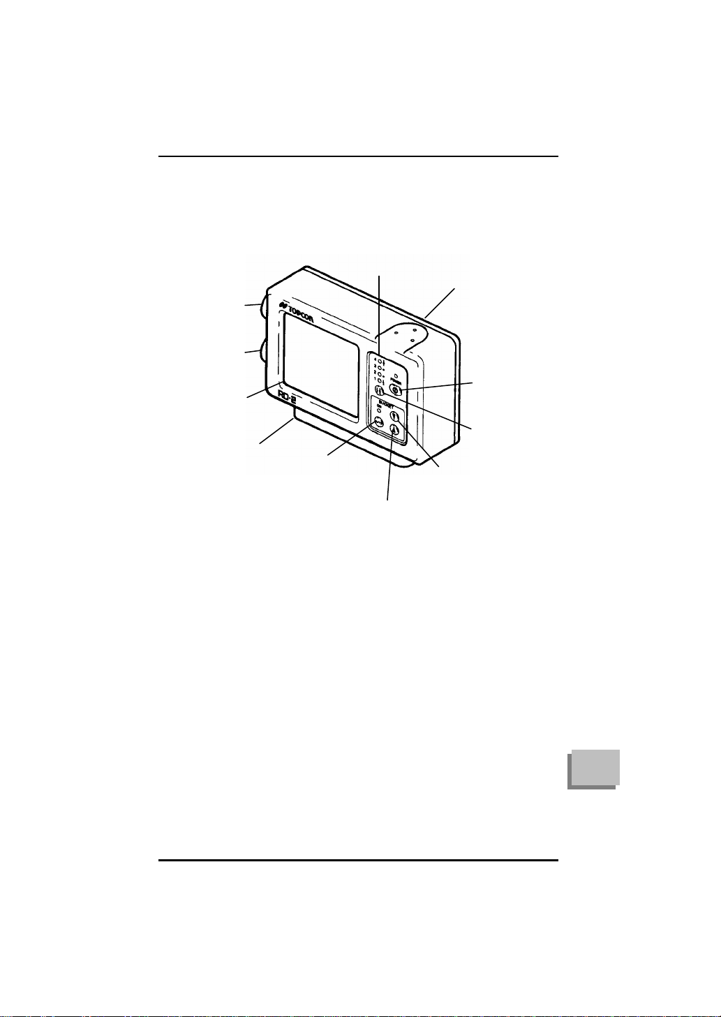
The LS-B2 has a unique infrared communication option called the
IR-2. The IR-2 receives an infrared signal from the LS-B2 and
transfers that signal to the RD-2 remote display mounted in the cab.
Used with the on-board battery pack, the infrared option removes
the need for cables between the LS-B2 and RD-2. This is an
advantage where routing cables from the sensor to the cab or from
the sensor to the battery is difficult and prone to accident.