Topcon LS-B200W User manual

1
INSTRUCTION MANUAL
LASER SENSOR
LS-B200W
Thank you for purchasing the TOPCON LS-B200W.
For the best performance of the instruments, please read these instructions
carefully and keep them in a convenient location for future reference.
GENERAL HANDLING PRECAUTIONS
Before starting work or operation, be sure to check that the system is functioning
properly.
• Remove the batteries from the instrument when you will not be using it for
long period.
• Replace all 4 batteries with new ones at the same time. Do not mix used and
new batteries, and do not mix different types of batteries together.
• Use alkaline dry batteries. Nickel hydrogen dry batteries and nickel cadmium
dry batteries can be used too, but the operating time is different from the time
of alkaline dry batteries.
• Do not submerge the instrument in water.
• This instrument is designed based on the International Standard IPX 6, but it
is not protected from a high pressure water stream or submergence.
• When washing the instrument, avoid spraying it with a high pressure stream
of water from a water hose. The inside of the instrument will be damaged by
the water.
• Be sure to charge the battery within the charging temperature range.
Charging temperature range: 10 to 40°C
• Battery is an expendable item. The decline in retained capacity depending on
the repeated charging/discharging cycle is out of warranty.
• Affection of the radio waves
When using the instrument in the following place, the strong radio wave may
cause faulty operation.
• Near the instrument occurring strong radio waves. (e.g. Transceiver)
• Near the radio wave towers such as television or radio.
• When transporting the instrument, provide some protection to minimize risk of
shock. Heavy shock may affect beam accuracy.
• In addition to the laser beam emitted from the rotating laser, the laser sensor
may be sensitive to smartphone screens, LED lamps, fluorescent lamps, con-
striction lamps, and other modulated lights. In this case, turn off these modu-
lated lights that may be the cause, or block them before performing
measurement.
• If an object (glass window, car windshield, etc.) that may reflect a laser beam
is close to this instrument, the laser sensor may malfunction. When using this
instrument, block the laser beam to the direction of a reflective object.
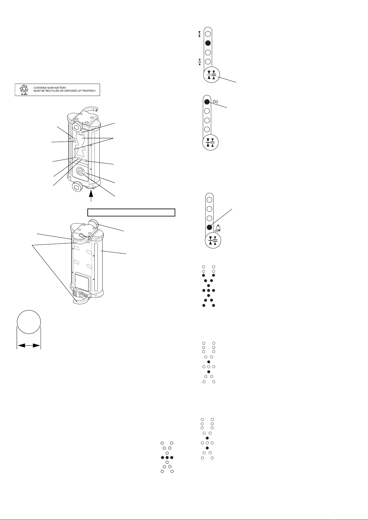
Examples of malfunctions:
• The display shows " " even though the location is not a datum posi-
tion.
• Errors occur for the datum position.
• The display does not show " " even though the loca-
tion is a datum position.
• Be sure that the laser emitting window of this instrument, and
the beam receiving window of the laser sensor are free from dirt
(oil, water droplets, etc.). The measurement result may be in
error if these windows are dirty.
•Bluetooth Wireless Technology
•Bluetooth function may not be built in depending on telecommunications
regulations of the country or the area where the instrument is purchased.
Contact your local dealer for the details.
• Use of this technology must be authorized according to telecommunica-
tions regulations of the country where the instrument is being used. Con-
tact your local dealer in advance. ( "Regulatory Information“)
• TOPCON CORPORATION is not liable for the content of any transmission
nor any content related thereto. When communicating important data, run
tests beforehand to ascertain that communication is operating normally.
• Do not divulge the content of any transmission to any third party.
• Radio interference when using Bluetooth technology
Bluetooth communication with the LS-B200W uses the 2.4 GHz frequency
band. This is the same band used by the devices described below.
• Industrial, scientific, and medical (ISM) equipment such as microwaves
and pacemakers.
• portable premises radio equipment (license required) used in factory pro-
duction lines etc.
• portable specified low-power radio equipment (license-exempt)
• IEEE802.11b/IEEE802.11g/IEEE802.11n/IEEE802.11ax standard wire-
less LAN devices.
The above devices use the same frequency band as Bluetooth communi-
cations. As a result, using the LS-B200W within proximity to the above
devices may result in interference causing communication failure or
reduction of transmission speed.
Although a radio station license is not required for this instrument, bear in mind
the following points when using Bluetooth technology for communication.
• Do not use the LS-B200W in proximity to microwaves.
• Microwave ovens can cause significant interference resulting in commu-
nication failure. Perform communication at a distance of 3m or more
from microwave ovens.
• Regarding portable premises radio equipment and portable specified low-
power radio equipment:
• Before starting transmission, check that operation will not take place
within the vicinity of portable premises radio equipment or specified low-
power radio equipment.
• In the case that the instrument causes radio interference with portable
premises radio equipment, terminate the connection immediately and
take measures to prevent further interference (e.g. connect using an
interface cable).
• In the case that the instrument causes radio interference with portable
specified low-power radio equipment, contact your local dealer.
• When using Bluetooth function in proximity to IEEE802.11b/IEEE802.11g/
IEEE802.11n/ IEEE802.11ax standard wireless LAN devices, turn off all
devices not being used.
• Interference may result, causing transmission speed to slow or even
disrupting the connection completely. Turn off all devices not being used
and vice versa.
• Refrain from using the LS-B200W in proximity to televisions and radios.
• Televisions and radios use a different frequency band to Bluetooth com-
munications. However, even if the LS-B200W is used within proximity to
the above equipment with no adverse effects with regard to Bluetooth
communication, moving a Bluetooth compatible device (including the
LS-B200W) closer to said equipment may result in electronic noise in
sound or images, adversely affecting the performance of televisions and
radios.
• Precautions regarding transmission
• For best results
• The usable range becomes shorter when obstacles block the line of
sight, or devices such as PDAs or computers are used. Wood, glass and
plastic will not impede communication but the usable range becomes
shorter. Moreover, wood, glass and plastic containing metal frames,
plates, foil and other heat shielding elements as well as coatings con-
taining metallic powders may adversely affect wireless communication
and concrete, reinforced concrete, and metal will render it impossible.
• Use a vinyl or plastic cover to protect the instrument from rain and mois-
ture. Metallic materials should not be used.
• Reduced range due to atmospheric conditions
• The radio waves used by the LS-B200W may be absorbed or scattered
by rain, fog, and moisture from the human body with the limit of usable
range becoming lower as a result. Similarly, usable range may also
shorten when performing communication in wooded areas. Moreover,
as wireless devices lose signal strength when close to the ground, per-
form communication at as high a position as possible.
TOPCON CORPORATION cannot guarantee full compatibility with all Blue-
tooth products on the market.
PRECAUTIONS FOR SAFE OPERATION
For the safe use of the product and prevention of injury to operators and other
persons as well as prevention of property damage, items which should be
observed are indicated by an exclamation point within a triangle used with
WARNING and CAUTION statements in this operator's manual.
The definitions of the indications are listed below. Be sure you understand them
before reading the manual's main text.
DEFINITION OF INDICATION
WARNING Ignoring this indication and making an operation error could possibly
result in death or serious injury to the operator.
CAUTION Ignoring this indication and making an operation error could possibly
result in personal injury or property damage.
This symbol indicates items for which caution (hazard warnings inclusive) is urged.
Specific details are printed in or near the symbol.
This symbol indicates items which are prohibited. Specific details are printed in or near
the symbol.
This symbol indicates items which must always be performed. Specific details are
printed in or near the symbol.
WARNING
There is a risk of fire, electric shock or physical harm if you attempt to disassemble or repair the
instrument yourself.
This is only to be carried out by TOPCON or an authorized dealer, only!
Risk of fire or electric shock.
Do not use damaged power cable, plug and socket.
Risk of fire or electric shock.
Do not use a wet battery.
May ignite explosively.
Never use an instrument near flammable gas, liquid matter, and do not use in a coal mine.
Battery can cause explosion or injury.
Do not dispose in fire or heat.
To prevent shorting of the dry battery in storage, apply insulating tape or equivalent to the termi-
nals. Otherwise shorting could occur, resulting in fire or burns.
Battery can cause explosion or injury.
Remove battery when using the connector for external power supply.
Do not use within the vicinity of hospitals. Malfunction of medical equipment could result.
Use the instrument at a distance of at least 22 cm from anyone with a cardiac pacemaker.
Otherwise, the pacemaker may be adversely affected by the electromagnetic waves produced
and cease to operate as normal.
Do not use onboard aircraft. The aircraft instrumentation may malfunction as a result.
Do not use within the vicinity of automatic doors, fire alarms and other devices with automatic
controls as the electromagnetic waves produced may adversely affect operation resulting in an
accident.
CAUTION
Do not touch liquid leaking from dry batteries. Harmful chemicals could cause burns or blisters.

2
STANDARD PACKAGE COMPONENTS
• LS-B200W Instrument .............................................. 1pc.
• Carrying case............................................................ 1pc.
• Instruction manual .................................................... 1pc.
•Laser Manager Guide ................................................ 1pc.
•Regulatory Information............................................... 1pc.
Dry battery type*
• Battery holder DB-83 ............................................ 1pc.
Dry cell batteries(4 x C) are sold separately.
*In some destinations, a rechargeable battery is already set in the main unit.
Rechargeable battery type (Optional accessories)
• Ni-MH battery pack BT-83Q.................................. 1pc.
• AC/DC converter AD-11 ........................................ 1pc.
PARTS OF THE INSTRUMENT AND FUNCTIONS
REPLACING THE BATTERY
Dry battery
1
Remove the DB-83 battery holder by turning the battery cover knob.
2Remove the old batteries and replace with new ones.
Rechargeable battery
1
Remove the BT-83Q by turning the battery cover knob.
2Attach the charged BT-83Q to the LS-B200W.
3Attach the battery cover by turning the battery cover knob.
• Batteries generate power using a chemical reaction and as a result have a limited life-
time. Even when in storage and not used for long periods, battery capacity deteriorates
with the passage of time. This may result in the operating time of the battery shortening
despite having been charged correctly. In this event, a new battery is required.
OPERATION
1
Position a rotating laser and turn on the laser.
2Raise or lower the machine blade or arm to position the cutting
edge or bucket at the desired grade elevation.
3Mount the LS-B200W onto the mast near the path of the laser
beam and turn on the LS-B200W.
4Keep the machine blade or arm motionless and raise or lower
the LS-B200W and adjust until ON-GRADE position are blink-
ing. This is the ON GRADE position.
5Securely clamp the LS-B200W in place. The reference position
has been set.
6While operating, use the LED display to continually check grade, moving
the blade or cutting / filling according to the direction of the LS-B200W dis-
play.
INDICATOR
Shape: Cylindrical
Dimension: 45 to 51mm in diameter
Please refer to the instruction manual for the machine or
contact the machine manufacturer for instructions on
installing the mast onto the machine (by welding, etc.).
45 to 51mm
Tilt indicator
Battery holder/Battery pack
(DB-83/BT-83Q)
Battery cover knob
Power switch
Power ON: Short press
Power OFF: Long press
Detective precision
(Mode) switch
Clamp knob
Detector
Detector
Clamp
Connector for external communication
Please refer to the page 2 of
the instruction manual for the
indicator display patterns.
Remove the battery when connecting.
Pipes that can be installed onto the LS-B200W are as described below.
Bluetooth wireless
communication
switch
Bluetooth wireless
communication LED
Zero-set switch
Tilt switch
Indicator
ON-GRADE
Rotating laser battery warning display
A blink shows that the rotating laser power is low.
(This function is not usable to the rotating laser which does
not have the function to output alarm signal.)
Goes out:
Battery is sufficient. (When Mode 1 is selected, the lamp will
light up.)
Blinks slowly:
The power is low, but sensor is still usable.
Blinks quickly:
Dead battery. Replace the dry battery with new one or recharge
the battery (BT-83Q Optional accessories).
Mode1
Mode2
Mode3
Mode4
Precision mode
LS-B200W Battery remaining display
Battery remaining display LED
Rotating laser battery remaining warning LED
It is possible to change the detective precision of the
instrument. Please select Mode 1 to 4 according to the
objective of the operation.
(”Laser beam positions and display patterns”)
Pressing the detective precision (Mode) switch will change
the mode and the corresponding LED lamp will light up.
(During battery remaining display shown below, the lamp
will blink.)
Battery remaining for the LS-B200W will be displayed at 3 lev-
els.
Height alert warning of rotating laser
A blink signifies that the height alert function of rotating laser is
operating.
(This function is not usable to the rotating laser which does not
have the height alert and the function to output alarm signal.)
Blinks
Power-save function (Effective only when using the internal battery)
Blinks
This instrument will enter the power-save mode when no
switches are operated or no laser beam is received for about
five minutes. During the power-save mode, two LEDs (one yel-
low and one red) will blink. (When the laser beam is received
again, the power-save mode will be automatically turned off. Or
when the power switch is pressed again, the power-save mode
will be also turned off.)
To disable the power-save function, press the power switch for
at least five seconds to turn the power on. When the function is
disabled, the LED shown in the figure will blink twice.
Auto-cut off function (Effective only when using the internal battery)
Detective precision (Mode) switch
Blinks
This instrument will automatically power off when no switches
are operated or no laser beam is received for about 60 minutes
after entering the power-save mode. (To use the instrument
again, press the power switch once again.)
To disable the auto-cut off function, press the power switch for
at least five seconds to turn the power on. When the function is
disabled, the LED shown in the figure will blink twice.

3
LED brightness adjustment function
(Effective only when using the internal battery)
This instrument detects the ambient brightness and automatically adjusts the LED bright-
ness (high/low). If you want to keep the LED brightness high, turn the power switch on
while holding down the detective precision (Mode) switch.
Laser beam positions and display patterns
TILT DETECTION FUNCTION
Switching the tilt direction
The tilt direction can be changed.
1
Long-press the detective precision(Mode) switch and the tilt switch at the
same time. The tilt direction mode setting changes in the following order:
"Back and Forth," "OFF" and "Right and Left." At this time, the LED at the
side of the mark indicating the tilt direction will blink. The LED will not blink
when the tilt detection function is switched OFF.
Switching the tilt precision
1
Short-press the tilt switch. The tilt precision will change. At this time, the LED
at the side of the mark indicating the tilt precision will light up.
Zero position setting for the tilt sensor
Before using the tilt detection function, set the zero position of the tilt sensor
according to the directions below. The tilt direction must be set before setting the
zero position.
1
Raise or lower the machine blade or arm where the LS-B200W is installed to
position the cutting edge or bucket at the desired slope.
2Long-press the tilt switch. The tilt angle for the LS-B200W will set to 0º.
To set the vertical zero position of tilt sensor to perpendicular.
1
Vertically position the machine blade or arm where the LS-B200W is installed.
2Rotate the LS-B200W on the pole each by 90º, and confirm that the green
LED in the tilt indicator is blinking in all directions.
3Set the zero position.
TILT ANGLES AND DISPLAY PATTERNS
Tilt directions: Right and Left
Tilt directions: Back and Forth
CHANGING THE ON-GRADE POSITION FUNCTION
The ON-GRADE position can be changed to the position where laser beam is
detected. Using this function when installing the LS-B200W on the pole of the
machine allows easy setting of the height at which the ON-GRADE will be dis-
played on the LS-B200W. The range in which the ON-GRADE position can be
changed is ±75mm (total of 150mm) from the center of the detective range.
In order to set the ON-GRADE position at high precision, set it while the laser
beam is stable. When setting the ON-GRADE position while the laser beam is
unstable (when using at a long-distance - more than 150m - or when atmo-
spheric condition is unstable due to air shimmering or other
conditions), the sensor will automatically detect it and the LED indicating the fail-
ure will be displayed while changing the ON-GRADE position.
Indicator (LED) Detective precision
Mode1: ±3mm (0.009ft)
Mode2: ±6mm (0.019ft)
Mode3: ±15mm (0.049ft)
Mode4: ±30mm (0.098ft)
±15mm/±0.05ft
(30mm/0.1ft width)
±30mm/±0.1ft
(60mm/0.2ft width)
When the laser beam is off
to the top or to the bottom
Blinks slowly
Blinks quickly
±50mm/±0.16ft
(100mm/0.33ft width)
±70mm/±0.23ft
(140mm/0.46ft width)
±125mm/±0.41ft
(250mm/0.82ft width)
Blinks more slowly
Blinks quickly
Blinks slowly
Tilt direction mark: Right and LeftTilt direction mark: Back and Forth
Tilt precision mark: High precision Tilt precision mark: Normal precision
The LED lights up as shown in the figure for three sec-
onds when the zero position is set.
The LED blinks as shown in the figure for three sec-
onds when you have failed to set the zero position.
High precision : ±1°
Normal precision : ±2.5°
Blinks quickly
±5°
More than ±5°
Blinks slowly
Lights off
High precision : ±1°
Normal precision : ±2.5°
High precision : More than ±1°
Normal precision : More than ±2.5°
Tilt indication will be displayed during laser detection and for 20 seconds
after switch operation.

4
Setting the ON-GRADE position change
1
Long-press the zero-set switch while detecting the laser beam.
The LED display while changing the ON-GRADE position
The LED display indicating beam position and the LED (1 green) in the center
will blink.
Canceling the ON-GRADE position change
1
Long-press the zero-set switch when not detecting the laser beam. The ON-
GRADE position will be reset.
Bluetooth CONNECTION
Using Bluetooth communication, LS-B200W can be remotely controlled by
devices such as iPhone and AndroidTM.
•Bluetooth function may not be built in depending on telecommunications reg-
ulations of the country or the area where the instrument is purchased. Con-
tact your local dealer for the details.
• Up to five units of the LS-B200W can be stored for pairing with the controller.
If more than five units are paired, they will be deleted in order from oldest to
newest.
• When connected with a controller, the connection is held until the time men-
tioned below.
• When canceling the connection from the controller;
or
• When pairing is performed with any other controller.
• "Laser Manager" is the name of software used to remotely control and sup-
port laser products. It works on devices such as iPhone and Android. The
control application "Laser Manager" would be better installed on your control-
ler in advance.
• If LS-B200W is not displayed during the pairing search in Laser Manager,
please complete pairing on the OS. After that, please do pairing again by
Laser Manager.
• When pairing with some instruments on Laser Manager, Bluetooth con-
nection between instrument and Laser Manager may take some time.
Please remove unnecessary instruments from Bluetooth connection his-
tory list on Laser Manager.
• After disconnecting Bluetooth by Laser Manager, the instrument icon may
not be displayed on the search screen. Please wait for a while and re-
enter the Bluetooth connection screen again.
Installing laser manager
There are two ways to install Laser Manager:
• Scan the QR code according to the instructions of the included “Laser man-
ager guide”.
• Search for "Laser Manager" on the App Store or Google Play.
For details on App Store and how to install this application, see the Apple
support home page (https://support.apple.com).
For details on Google Play and how to install this application, see the Google
support home page (https://support.google.com).
Pairing
1
Turn on the LS-B200W.
2Press and hold down the Bluetooth wireless communication switch; the
Bluetooth wireless communication LED will light up/blink as follows.
3With the LED lit, start Laser Manager installed on the controller and search
for the Bluetooth device.
4Select the LS-B200W you want to connect from the Bluetooth devices dis-
played. The LED will blink rapidly to suggest pairing is completed.
Connecting to a paired controller
1
Start Laser Manager.
2Select the LS-B200W you want to connect.
3Connection to the controller is completed; you can remotely control the LS-
B200W from the Laser Manager screen.
CONNECTOR FOR EXTERNAL COMMUNICATION
The LS-B200W can be used as the laser detecting sensor for any TOPCON
machine control system by connecting the communication cable to the connector
for external communication. (Please contact your sales agent for details.)
Connecting the connector cable PC-18 (sold separately) to the connector for exter-
nal communication will enable the use of the LS-B200W from an external power
supply. When the instrument is operated with the external power supply, the power-
save and the auto-cut off functions will be invalidated. The LS-B200W will turn on
when connection is made to external power supply. The power switch of the instru-
ment will not function when an external power supply is used. Wireless communica-
tion will not function when using external communication or an external power
supply.
Bluetooth connection is not available while making external communication and
using external power supply.
SPECIFICATIONS
• App Store is a trademark or a service mark of Apple Inc., registered in the U.S. and other countries.
• iPhone is trademarks of Apple Inc., registered in the U.S. and other countries.
• Android and Google Play are trademarks of Google LLC.
• QR Code is a registered trademark of DENSO WAVE.
•Bluetooth is a registered trademark of Bluetooth SIG, Inc.
• All other company and product names featured in this manual are trademarks or registered trademarks of each
respective organization.
When changing the ON-GRADE position, the LED
lights up for three seconds, as shown in the figure. The
position where the laser beam is being detected will be
the ON-GRADE position.
The LED lights up as shown in the figure for three sec-
onds when you have failed to change the ON-GRADE
position. Be careful not to change the position at which
the laser beam is detected and try setting once again.
Blinks
Blinks quickly
When the ON-GRADE position change is cancelled,
the LED (3 green) will blink for three seconds.
Blinks
Lit Communication initialization in progress
Blinks quickly While LS-B200W is communicating
Blinks slowly Communication is in preparation
Detective range : 250mm (9.8 in) (The range in which the ON-GRADE
position can be changed : 150mm)
Detective angle : 360°
Detective precision : Mode1: ±3mm (0.009ft)
: Mode2: ±6mm (0.019ft)
: Mode3: ±15mm (0.049ft)
: Mode4: ±30mm (0.098ft)
Detectable laser wave length : 633 to 785nm
Laser detecting range
(diameter)
: 800m (2625ft)
(Using the RL-200 1S/2S)
Bluetooth wireless communica-
tion* :Bluetooth 5.0(Low Energy / Classic)
Transmission method : FHSS
Modulation : GFSK [Classic(1Mbps) or BLE]
: 4-DQPSK [Classic(2Mbps)]
: 8-DPSK [Classic(3Mbps)]
Frequency band : 2.402GHz to 2.480GHz
Bluetooth profile : SPP, GATT(TOPCON Transfer Service)
Power class : Class 1
Usable range : 20m
(May vary depending on obstacles between the two
instruments as well as other conditions)
Internal battery :
:
C-size dry batteries 4pcs.(sold separately)
Battery pack BT-83Q (sold separately)
External power supply : DC 10 to 30V
Continuous operating time*
(20°C/68°F)
: More than 80 hours
(Using alkaline manganese dry batteries)
: More than 40 hours(Using Battery pack BT-83Q)
Battery using time will vary depending on environmen-
tal conditions and operations done with LS-B200W.
Operating temperature : -20 to 50°C (-4 to 122°F)
Water proof : IP66 (Based on the standard IEC60529)
Dimensions (W/D/H) : 158x166x357 (mm) (6.2x6.5x14.0 (in))
(With Mechanical Clamp)
Weight (Without batteries) : 2.2kg (4.8lbs)
Detective angle, Detective precision and Laser detecting range may vary depending on rotat-
ing laser being used or atmospheric conditions.
EXCEPTIONS FROM RESPONSIBILITY
• The manufacturer, or its representatives, assumes no responsibility for any damage, or loss
of profits (change of data, loss of data, loss of profits, an interruption of business etc.)
caused by use of the product or an unusable product.
• The manufacturer, or its representatives, assumes no responsibility for any damage, or loss
of profits caused by usage different to that explained in this manual.
• The manufacturer, or its representatives, assumes no responsibility for consequential dam-
age, or loss of profits due to heavy rain, strong wind, high-temperature and humidity, or
storing or use of the product under unusual conditions.
• Product failures caused by rebuilding are out of warranty.
• Cautions and warnings included in this manual do not cover all the possible events.
1054307 -01-A
https://www.topcon.co.jp
GLOBAL GATEWAY https://global.topcon.com
Please see the following website for contact addresses.
2022

REGULATORY INFORMATION
LASER SENSOR
LS-B200W
[U.S.A.] FCC Compliance (FCC-Class B)
WARNING:
Changes or modifications to this unit not expressly approved by the party responsi-
ble for compliance could void the user's authority to operate the equipment.
NOTE:
This equipment has been tested and found to comply with limits for a Class B digital
device, pursuant to Part 15 of the FCC Rules. These limits are designed to provide
reasonable protection against harmful interference in a residential installation. This
equipment generates, uses, and can radiate radio frequency energy and, if not
installed and used in accordance with the instructions, may cause harmful interfer-
ence to radio communications.
However, there is no guarantee that interference will not occur in a particular instal-
lation. If this equipment does cause harmful interference to radio or television
reception, which can be determined by turning the equipment off and on, the user is
encouraged to try to correct the interference by one or more of
the following measures:
- Reorient or relocate the receiving antenna.
- Increase the separation between the equipment and receiver.
- Connect the equipment into an outlet on a circuit different from that to which
the receiver is connected.
- Consult the dealer or an experienced radio / TV technician for help.
Means of conformity
This transmitter must not be co-located or operated in conjunction with any other
antenna or transmitter.
This equipment complies with FCC radiation exposure limits set forth for an uncon-
trolled environment and meets the FCC radio frequency (RF) Exposure Guidelines.
This equipment has very low levels of RF energy that is deemed to comply without
maximum permissive exposure evaluation (MPE). But it is desirable that it should
be installed and operated keeping the radiator at least
20cm or more away from person's body.
[California, U.S.A.] Proposition65
[California and NY, U.S.A.] Recycling Batteries
[Canada] ICES (ICES-Class B)
This class B digital apparatus meets all requirements of Canadian interference-
Causing Equipment Regulations.
Cet appareil numerique de la class B respecte toutes les exigences du Reglement
sur le materique brouilleur du Canada.
This Class B digital apparatus complies with Canadian ICES-003.
Cet appareil numerique de la Class B est conforme a la norme NMB-003 du Can-
ada.
Operation is subject to the following two conditions: (1) this device may not cause
interference, and (2) this device must accept any interference, including interfer-
ence that may cause undesired operation of this device.
This equipment complies with IC radiation exposure limits set forth for an uncon-
trolled environment and meets the RSS-102 of the IC radio frequency (RF) Expo-
sure Guidelines.
This equipment has very low levels of RF energy that is deemed to comply without
maximum permissive exposure evaluation (MPE). But it is desirable that it should
be installed and operated keeping the radiator at least 20cm or more away from
person's body.
[EU/UK] EMC NOTICE (EMC-Class B, RE)
In industrial locations or in proximity to industrial power installations, this instrument
might be affected by electromagnetic noise. Under such conditions, please test the
instrument performance before use.
This product complies with the electromagnetic environmental testing of industrial
locations.
Hereby, TOPCON CORPORATION declares that the radio equipment type of this
product is in compliance with Directive 2014/53/EU. The full text of the EU declara-
tion of conformity is available at the following internet address:
https://mytopconnow.topconpositioning.com
Manufacturer
Name: TOPCON CORPORATION
Address: 75-1, Hasunuma-cho, Itabashi-ku, Tokyo, 174-8580 JAPAN
Europe Representative and Importer
Name: Topcon Europe Positioning B.V.
Address: Essebaan 11, 2908 LJ Capelle a/d IJssel, The Netherlands
UK Importer
Name: Topcon Positioning (Great Britain) Ltd.
Address: Unit 2 Sandy Hill Park, Sandy Way, Tamworth, Staffordshire B77
4DU U.K.
[EU] WEEE Directive
[UK] The Waste Electrical and Electronic Equipment
Regulations
[EU] EU Battery Directive
[UK] The Waste Batteries and Accumulators
Regulations 2009
[China] Chinese Environmental Directive
WARNING:
This product can expose you to chemicals including Lead, which is known to the
State of California to cause birth defects or other reproductive harm.
For more information go to www.P65Warnings.ca.gov.
DON’T THROW AWAY RECHARGEABLE BATTERIES, RECYCLE THEM.
Topcon Positioning Systems Inc., United States Return Process for
UsedRechargeable Nickel Metal Hydride, Nickel Cadmium, Small Sealed Lead
Acid, and Lithium Ion, Batteries
In the United States Topcon Positioning Systems Inc., has established a process by
which Topcon customers may return used rechargeable Nickel Metal Hydride(Ni-MH),
Nickel Cadmium(Ni-Cd), Small Sealed Lead Acid(Pb), and Lithium Ion(Li-ion) batteries
to Topcon for proper recycling and disposal. Only Topcon batteries will be accepted in
this process.
Proper shipping requires that batteries or battery packs must be intact and show no
signs of leaking. The metal terminals on the individual batteries must be covered with
tape to prevent short circuiting and heat buildup or batteries can be placed in individual
plastic bag. Battery packs should not be dissembled prior to return.
Topcon customers are responsible for complying with all federal, state, and local
regulations pertaining to packing, labeling, and shipping of batteries. Packages must
include a completed return address, be prepaid by the shipper, and travel by surface
mode. Under no circumstance should used/recyclable batteries by shipped by
air.
Failure to comply with the above requirements will result in the rejection of the package
at the shipper’s expense.
Please remit packages to: Topcon Positioning Systems, Inc.
C/O Battery Return Dept. 150
7400 National Dr.
Livermore, CA 94551
DON’T THROW AWAY RECHARGEABLE BATTERIES, RECYCLE THEM.
The use of the symbol indicates that this product may not be treated as
household waste. By ensuring this product is disposed of correctly, you
will help prevent potential negative consequences for the environment
and human health, which could otherwise be caused by inappropriate
waste handling of this product. For more detailed information about the
take-back and recycling of this product, please contact your supplier where you
purchased the product or consult.
Battery users must not dispose of batteries as unsorted general waste,
but treat properly.
If a chemical symbol is printed beneath the symbol shown above, this
chemical symbol means that the battery or accumulator contains a
heavy metal at a certain concentration. This will be indicated as follows:
Hg: mercury(0.0005%), Cd: cadmium(0.002%), Pb: lead(0.004%)
These ingredients may be seriously hazardous to human and the global environ-
ment.
1056662-01-A
https://www.topcon.co.jp
GLOBAL GATEWAY https://global.topcon.com
Please see the following website for contact addresses.
ƻ˖㺘⽪䈕ᴹ∂ᴹᇣ⢙䍘൘䈕䜘Ԧᡰᴹ൷䍘ᶀᯉѝⲴ䟿൷൘⭥ᆀؑӗ૱ѝᴹ∂ᴹᇣ
⢙䍘Ⲵ䲀䟿㾱≲ḷ߶㿴ᇊⲴ䲀䟿㾱≲ *%7 ԕл
h˖㺘⽪䈕ᴹ∂ᴹᇣ⢙䍘㠣ቁ൘䈕䜘ԦⲴḀа൷䍘ᶀᯉѝⲴ䟿䎵ࠪ⭥ᆀؑӗ૱ѝᴹ
∂ᴹᇣ⢙䍘Ⲵ䲀䟿㾱≲ḷ߶㿴ᇊⲴ䲀䟿㾱≲ *%7
7KLVLQIRUPDWLRQLVDSSOLFDEOHIRU3HRSOHV5HSXEOLFRI&KLQDRQO\
⧟؍֯⭘ᵏ䲀ḷ䇶ᱟṩᦞ lj⭥ಘ⭥ᆀӗ૱ᴹᇣ⢙䍘䲀ࡦ֯⭘㇑⨶࣎⌅NJԕ৺
lj⭥ಘ⭥ᆀӗ૱ᴹᇣ⢙䍘䲀ࡦ֯⭘ḷ䇶㾱≲NJ6-7 ࡦᇊⲴˈ䘲⭘Ҿ
ѝഭຳ䬰Ⲵ⭥ᆀؑӗ૱Ⲵḷ䇶DŽ
㾱᤹➗ᆹޘ৺֯⭘䈤᰾ᇩ൘↓ᑨ֯⭘⭥ᆀؑӗ૱ᛵߥлˈӾ⭏ӗᰕᵏ㇇䎧ˈ൘↔
ᵏ䲀ӗ૱ѝᴹⲴᴹ∂ᴹᇣ⢙䍘н㠤⭏ཆ⋴ᡆケˈн㠤ሩ⧟ຳ䙐ᡀѕ䟽⊑ḃᡆሩ
ަӪ䓛ǃ䍒ӗ䙐ᡀѕ䟽ᦏᇣDŽӗ૱↓ᑨ֯⭘ˈ㾱ᓏᔳ൘⧟؍֯⭘ᒤ䲀ᡆ㘵ࡊࡠᒤ䲀
Ⲵӗ૱ˈ䈧ṩᦞഭᇦḷ߶䟷䘲ᖃⲴᯩ⌅䘋㹼༴㖞DŽ ཆˈ↔ᵏ䲀нҾ䍘䟿 ࣏㜭
Ⲵ؍䇱ᵏ䲀DŽ
7KH0DUNDQG,QIRUPDWLRQDUHDSSOLFDEOHIRU3HRSOHV5HSXEOLFRI&KLQDRQO\
䫵
3E
⊎
+J
䭹
&G
ޝԧ䬜
&U9,˅
ཊⓤ㚄㤟
3%%
ཊⓤҼ㤟䟊
3%'(
ᴹǂᇣǂ⢙ǂ䍘
˘ӗ૱ѝᴹᇣ⢙䍘Ⲵ〠৺䟿˚
ѫᵪ䜘ս h ƻ h ƻ ƻ ƻ
⭥Ⓚ䜘ս h ƻ ƻ ƻ ƻ ƻ
䱴Ԧ h ƻ ƻ ƻ ƻ ƻ
ⴂᆀ ƻ ƻ ƻ ƻ ƻ ƻ
䜘Ԧ〠
Table of contents
Other Topcon Accessories manuals

Topcon
Topcon LS-80A User manual

Topcon
Topcon LS-B2 User manual

Topcon
Topcon RH-1 User manual

Topcon
Topcon LS-B200 User manual

Topcon
Topcon LS-80A User manual

Topcon
Topcon LS-80A User manual

Topcon
Topcon LS-B4 User manual

Topcon
Topcon LS-B10 User manual

Topcon
Topcon LS-B100 User manual

Topcon
Topcon LS-B110 User manual
Popular Accessories manuals by other brands

Scaime
Scaime Epsiload 2I/SW Mounting instructions

Carlon
Carlon DH920 quick guide

SSC-LUXon
SSC-LUXon ZAVO Assembly & operating instructions

Cooper Lighting
Cooper Lighting Greengate OAWC-DT-120W installation instructions

DVS ZERT
DVS ZERT Compact Line CL5430.609 Assembly instructions

LEGRAND
LEGRAND LCS 0 337 96 quick start guide