Topdon AL500B User manual
AL500B
OBD-II Scanner & Battery Tester USER MANUAL

Manual Support in Other Languages
Safety Is Always the First Priority!
Section 1 What's in the Box?
Section 2 Product Overviews
Section 3 Using the Scan Tool
Section 4 Battery Test
Section 5 Review
Section 6 DTC Lookup
Section 7 Print
Section 8 Setting
Section 9 Help
Section 10 Info
Section 11 Update
Section 12 Technical Specication
Section 13 FAQ
Section 14 Warranty
Section 15 FCC
4
4
6
7
14
28
41
43
45
46
48
50
51
51
52
53
54
......................
......................
......................
......................
......................
......................
......................
......................
......................
......................
......................
......................
......................
......................
......................
......................
......................
CONTENTS

MANUAL SUPPORT IN OTHER
LANGUAGES
SAFETY IS ALWAYS THE FIRST
PRIORITY!
For your safety, the safety of others, the
product, and the vehicle you are working on,
PLEASE, CAREFULLY READ AND MAKE SURE
YOU FULLY UNDERSTAND ALL THE SAFETY
INSTRUCTIONS AND MESSAGES ON THIS
MANUAL. Given the AL500B is a combination
of OBD-II scanner and battery tester, YOU
MUST READ THE VEHICLE'S SERVICE MANUAL,
THE BATTERY MANUFACTURER’S SPECIFIC
PRECAUTIONS FOR THE BATTERY and follow
said precautions and instructions before and
during any test or service procedure.
To download the multilingual PDF of the manual, please
visit https://www.topdon.com/products/artilink500b.
Alternatively, you can scan the QR Code.
READ ALL INSTRUCTIONS BEFORE USING

EN |5
ONLY OPERATE THE TEST IN A WELL-
VENTILATED AREA since the vehicle produces
carbon monoxide, a toxic and poisonous gas,
and particulate matter when the engine is
running.
ALWAYS SHIFT THE GEAR TO P (FOR
AUTOMATIC TRANSMISSION) OR TO NEUTRAL
(FOR MANUAL TRANSMISSION) AND MAKE
SURE THE PARKING BRAKE IS ENGAGED.
ALWAYS BE AWARE OF MOVING PARTS (such
as coolant fans, pulleys, belts) since they spin
or turn at high speeds when the engine is
running.
ALWAYS WEAR APPROVED SAFETY EYE
PROTECTION to prevent damage from sharp
objects and caustic liquids.
TURN THE IGNITION OFF BEFORE CONNECTING
OR DISCONNECTING THE SCAN TOOL FROM
THE DATA LINK CONNECTOR (DLC) to prevent
causing damage to the scan tool or vehicle's
electronic components.
ALWAYS USE A DIGITAL MULTIMETER WITH
AT LEAST 10 MEGOHMS OF IMPEDANCE
when conducting electrical tests on vehicles
to prevent causing damage to on-board
electronic components.
NO SMOKING ANYWHERE NEAR THE VEHICLE
when testing. The fuel and battery vapors are
highly ammable.
DO NOT TOUCH HOT ENGINE PARTS to prevent
severe burns. The engine parts become very
hot when the engine is running.

DO NOT WEAR LOOSE CLOTHING OR JEWELRY
WHEN WORKING ON AN ENGINE. Loose
clothing can easily be caught in the engine's
fan, pulleys, belts, etc. and jewelry is highly
conductive, which causes severe burn or
electric shock if it contacts with electricity.
Battery acid is extremely corrosive. If acid gets
into your eyes, FLUSH THEM THOROUGHLY
WITH COLD RUNNING WATER FOR AT LEAST
20 MINUTES AND SEEK MEDICAL ATTENTION
IMMEDIATELY. If battery acid gets on your skin
or clothing, WASH IT IMMEDIATELY WITH A
SOLUTION OF WATER AND BAKING SODA.
AL500B
Battery Test Cable with Clamps
OBD-II 16-pin Connector Cable
Mini-USB Data Transfer Cable
Carrying Bag
User Manual
Quick User Guide
DO NOT CUT THE PRODUCTS CORDS OR
SUBMERGE THEM IN WATER. The product is
an electrical device that can cause shock and
severe burns.
SECTION 1
WHAT'S IN THE BOX?

EN |7
SECTION 2
PRODUCT OVERVIEWS
Controls & Connections
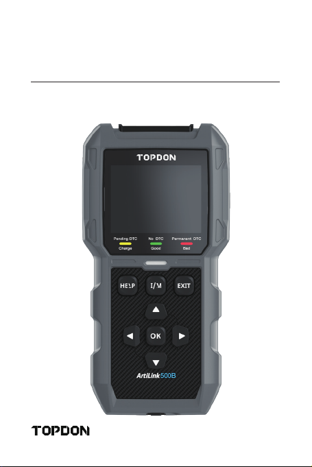
1. Display: The 2.8" colored screen shows menus, submenus,
test results, specic functions, monitor status info. For
further details, please refer to the following section Main
Menu & Home Screen Icons.(See Figure 2.1.1)
Figure 2.1.1
1
2
3
4
5
6

2. Indicator Status: The 3-color (green. yellow, red) LED
indicator shows the OBD-II diagnostic and battery test
results.
The Denition of 3-Color Indicator
● Green LED: Indicates that all on-board systems are
"OK" operating normally. There is no DTC stored in
the ECU. The battery is in a good condition and no
need to charge or replace it.
● Yellow LED: Indicates that the pending code(s) are
present. The battery is in a normal condition, might
need to be charged and tested again later.
● Red LED: Indicates that the permanent code(s) are
present. The battery is in a bad condition and needs
to be replaced.
3. Help Shortcut Button: When pressed, it leads you directly
to the Help menu, which includes the basic info of OBD-
II, Datastream, I/M Readiness, and instructions for printing
the report.
4. I/M Readiness Shortcut Button: When pressed, the scan
tool automatically communicates with the emission-
related system and monitor associated components such
as the fuel system, oxygen sensor, catalyst converter,
misre monitor, etc.
5. Exit Button: When pressed, it brings you back to the
previous menu.
6. Arrow Keys & OK Button.
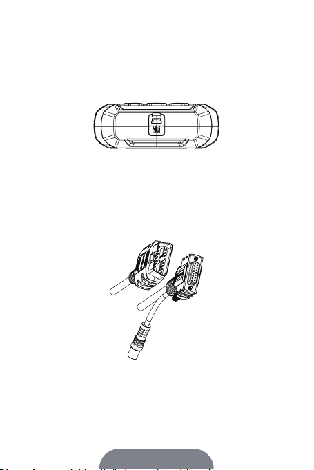
7. DB15 Male Connector: The connector is for you to connect
the OBD-II diagnostic cable and battery test cable. (See
Figure 2.1.2)
Figure 2.1.2
EN |9
● There is no built-in battery inside of the AL500B, so no
need to charge it. The Mini-USB port is only for data
transformation.
8. Mini-USB Port: This port is for you to connect to the PC to
transfer the diagnostic or battery test report. (See Figure
2.1.3)
● This connects to the DB15 Male connector at the top of
the ArtiLink 500B. The other end connects to the OBD
port.
9. Diagnostic Cable with DB15 Female Connector & 16-pin
OBD-II Port.(See Figure 2.1.4)
10. Battery Test Cable with DB15 Female Connector & Battery
Clamps. (See Figure 2.1.5)
● This can also be connected to the DB15 Male connector
to test the vehicle battery.
Figure 2.1.3
Figure 2.1.4

Figure 2.2.1
Figure 2.1.5
Main Menu & Home Screen Icons
Once the AL500B is connected to the power source (through
OBD-II Diagnostic Cable or Battery Test Cable), the 2.8" color
LCD screen will light up and display the main menu (See
Figure 2.2.1). To help you understand each icon, please read
the following content carefully.
The OBD-II/EOBD (See Figure 2.2.2) function allows you to
access "generic" OBD-II data, including DTCs, freeze frame,
datastream, etc. For detailed info, please go to Section 3

EN |11
Figure 2.2.2
Figure 2.2.3
The Battery Test (See Figure 2.2.3) function allows you to test
battery voltage, CCA, internal resistance, state of charge,
state of health, etc. For detailed info, please go to Section 4
Once I/M is selected, the AL500B will automatically
communicate with on-board systems to diagnose the
readiness status of emission-related systems, monitors, and
components. (See Figure 2.2.4)
Figure 2.2.4
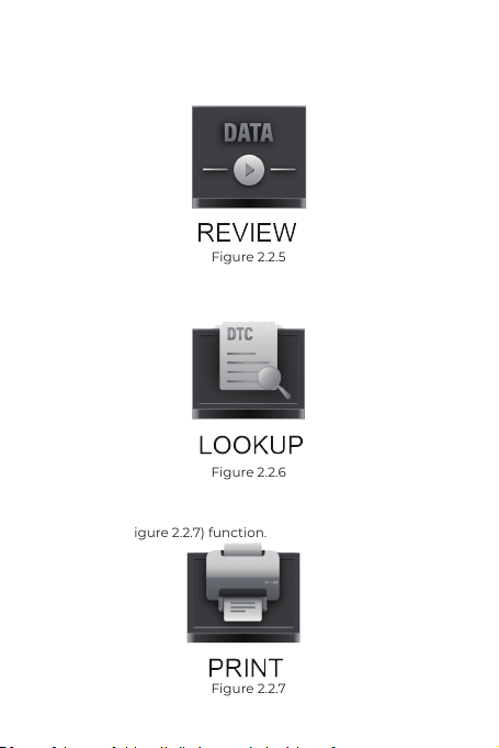
Figure 2.2.7
Figure 2.2.6
Figure 2.2.5
The REVIEW (See Figure 2.2.5) function stores the OBD-II
diagnostic and battery test records automatically for you to
review.
The LOOKUP (See Figure 2.2.6) refers to the DTC lookup
which gives you the specic denitions of DTCs.
After connecting the AL500B to the PC through a Mini USB
cable, you can access and print the test report through the
PRINT (See Figure 2.2.7) function.
EN |13
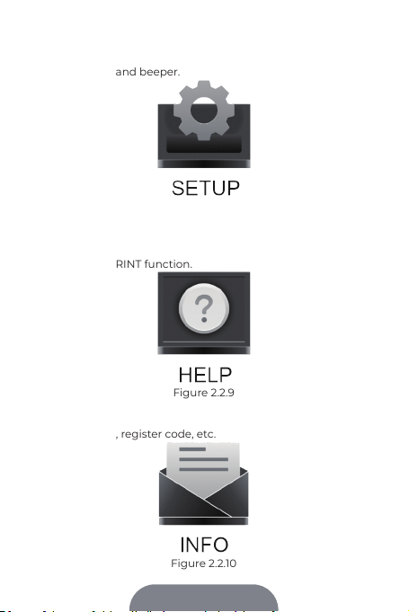
The SETUP (See Figure 2.2.8) function allows you to change
the settings of the scan tool, e.g., language, unit of measure,
record mode, and beeper.
The Help (See Figure 2.2.9) function provides you with
important information from the scan tool, e.g., the general
introduction of OBD, live data stream, I/M readiness, and the
notes of the PRINT function.
The Info (See Figure 2.2.10) provides you with the information
of the AL500B you purchased, including software version,
serial number, register code, etc.
Figure 2.2.8
Figure 2.2.9
Figure 2.2.10

Figure 3.1.1
SECTION 3
USING THE SCAN TOOL
Preparation
● DO NOT CONNECT THE SCAN TOOL TO THE VEHICLE
WHILE THE VEHICLE IS ON. Doing so could cause
damage to the scan tool or vehicle's electronic
components.
● Retrieving the DTCs is only one part of on-board
diagnostic. NEVER REPLACE THE PARTS SOLELY
BASED ON THE DIAGNOSTIC RESULTS. Always refer
to the vehicle's service manual for detailed testing
instructions.
● ALWAYS KEEP THE SAFETY PRECAUTIONS IN MIND
when working on a vehicle.
1. Turn the ignition off or to the "LOCK" position (0). (See
Figure 3.1.1)
2. Locate the vehicle's DLC
● Most of the vehicle's DLCs are located in one of the
positions labeled in Figure 3.1.2. Some DLCs have
a plastic cover that needs to be removed before
connecting and some are hidden nearby the fuse panel.
If you encounter a problem locating the DLC, please
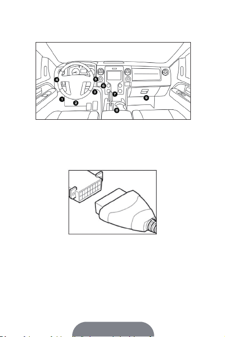
EN |15
Figure 3.1.2
Figure 3.1.3
3. Properly connect the scan tool to the DLC (See Figure 3.1.3).
The cable connector is keyed and will only t one way.
● If you cannot plug the cable in, please rotate the
connecter 180° and try it again.
4. Turn the ignition to the ON position (II) (See Figure 3.1.4),
DO NOT start the engine.
● If your vehicle is equipped with a keyless start system
and the ignition switch is an "engine start-stop" button
(See Figure 3.1.5), press the ignition button until the
car is in the "ON" Mode. Do not press the brake while
pressing the ignition button or you will start the car
instead of putting it in the "ON" position.
refer to the vehicle's service manual, or contact us with
specic vehicle information (e.g., VIN).

● The method of ignition varies by vehicle model. Please
refer to the service manual.
Figure 3.1.4 Figure 3.1.5
Figure 3.1.6
5. When the scan tool is properly connected to the DLC, the
units will start initializing and present you with the main
menu interface. (See Figure 3.1.6)
The Procedure of DTC Retrieval
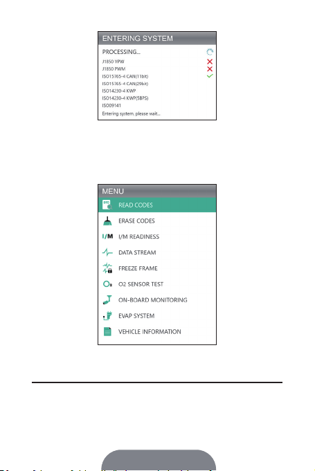
1. Once you've entered the OBD-II function, the scan tool
automatically communicates with the on-board computer
to determine the communication protocol. After it's
conrmed, the link is established. (See Figure 3.2.1)
● A PROTOCOL is a set of rules and procedures for
regulating data transmission between vehicles, and
testing equipment. Here are the ve different types of
protocols (ISO 9141, Keyword 2000, J1850 PWM, J1850
VPW and CAN) that are used by vehicle manufacturers.
EN |17
Figure 3.2.1
Figure 3.2.2
2. To retrieve the DTCs, please select Read Codes (See Figure
3.2.2), and press [OK]. The scan tool will communicate with
ECU and present you with DTCs.
● The procedure of clearing the DTCs should be
performed after the required repairing has been carried
1. Select the Erase Codes Icon (See Figure 3.3.1), and press
[OK]
Procedure for Clearing the DTCs
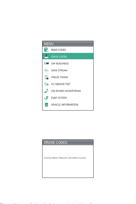
Figure 3.3.1
Figure 3.3.2
out. Once conrmed, the emission-related data stored
in the ECU will be reset or cleared, WHICH IS NOT
RETRIVEABLE.
● DO NOT START UP THE ENGINE WHILE CLEARING
THE CODES.
2. After determining that all repairs have been completed,
press [OK] to clear or reset the emission-related diagnostic
data. (See Figure 3.3.2)

EN |19
The I/M Readiness (See Figure 3.4.1) checks whether or
not the various emissions-related systems on the vehicle
are operating properly, and are ready for Inspection and
Maintenance testing.
It can also be used to conrm that the repair has been
performed correctly, and/or to check for monitor run status
after the repair has been performed.
● To perform the I/M Readiness function, you can also
press the I/M shortcut button. (See Figure 3.4.2)
1. Press the [OK] or the I/M shortcut button to perform this
function, the results will be presented on the screen. (See
Figure 3.4.3)
I/M Readiness
Figure 3.4.1 Figure 3.4.2

Figure 3.4.3
To help you understand the test results, we have listed the
full names of the abbreviated phrases below. You can also
press the HELP (See Figure 3.4.4) shortcut button to check
the full names of components and monitors.
● MIL - Malfunction Indicator Light
● IGN - The Ignition Method of the Vehicle
● DTC - Diagnostic Trouble Code
● Pd DTC -Pending Diagnostic Trouble Code
● MIS - Misre Monitor
● FUE - Fuel System Monitor
● CCM - Comprehensive Components Monitor
● CAT - Catalyst Monitor
● HCAT - Heated Catalyst Monitor
● EVAP - Evaporative System Monitor
● AIR - Secondary Air Monitor
● O2S - O2 Sensors Monitor
● HRT - 02 Sensor Heater Monitor
● EGR - Exhaust Gas Recirculation System Monitor
Figure 3.4.4

EN |21
● IF THE VEHICLE MUST BE DRIVEN TO VIEW THE LIVE
DATA STREAM, ALWAYS HAVE A SECOND PERSON
HELPING YOU. DO NOT WATCH THE DATA STREAM
WHILE DRIVING.
The AL500B allows you to view or record Live Data Stream
(See Figure 3.5.1) which includes values (volts, rpm,
temperature, speed, etc.) and system status information
(open-loop, closed-loop, fuel system status, etc.) generated
by the various vehicle sensors, switches, and actuators.
Data Stream
1. View All Items
Press [OK] to see the data streams. (See Figure 3.5.2)
● The values displayed may change as the vehicle's
engine is running.
Figure 3.5.1
Table of contents
Other Topdon Test Equipment manuals

Topdon
Topdon BTMOBILE PROS User manual

Topdon
Topdon ArtiHD I User manual

Topdon
Topdon BT100 User manual

Topdon
Topdon BT20 User manual

Topdon
Topdon BT200 User manual

Topdon
Topdon BT100W User manual

Topdon
Topdon BT600 User manual

Topdon
Topdon BT20 User manual

Topdon
Topdon BT50 User manual

Topdon
Topdon BT MOBILE User manual

Topdon
Topdon TB6000Pro User manual

Topdon
Topdon Phoenix Plus User manual

Topdon
Topdon BT300P User manual

Topdon
Topdon BTMOBILE lite User manual

Topdon
Topdon BT50 User manual

Topdon
Topdon ArtiPad I User manual

Topdon
Topdon BT20 User manual

Topdon
Topdon BT200 User manual

Topdon
Topdon Ultrascan OBDCAN PLUS User manual

Topdon
Topdon BT50 User manual


