Step 3
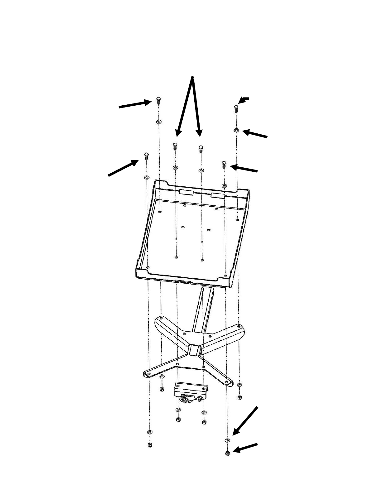
Align the outer holes in the Mounting Bracket with the holes in
the Generator Tray. For this installation, the tube on the
Mounting Bracket should be facing toward the side of the
Generator Tray with two rectangular slots.
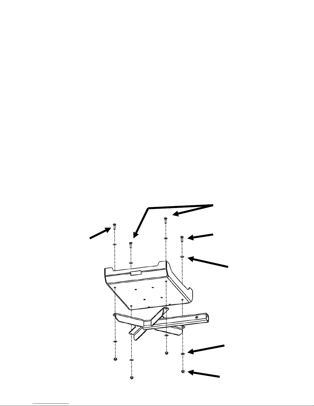
From the top of the tray, install one 3/8”-16 x 1-1/4” SS Hex Bolt
with one 3/8” SS SAE Flat Washer into one of the outer holes as
well as one diagonal from the bolt you have just installed. Install a
3/8”-16 x 1.25” SS Snake Eye Bolt using the supplied bit with a
3/8” SS SAE Flat Washer into the two remaining outer holes.
Secure the bottom of each bolt with one 3/8” SS SAE Flat Washer
and one 3/8”-16 Grade 8 Nylock Nut. See Figure 3.1
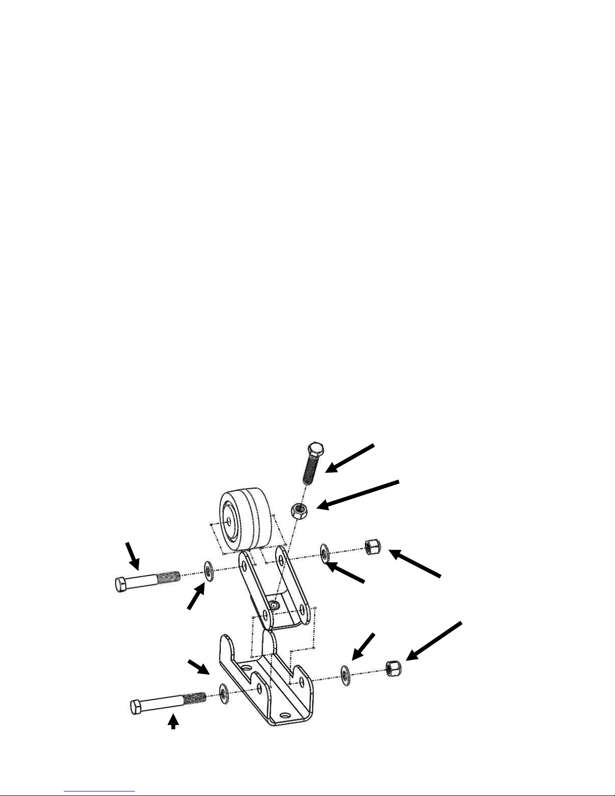
Align the two holes in the wheel bracket assembly with the two
holes in the Mounting Bracket. Figure 3.1 shows the wheel
bracket assembly positioned for a driver side space dock
installation. For passenger side installations, reverse the direction
of the wheel bracket from what is shown.
Install one 3/8”-16 x 1-1/4” SS Hex Bolt into each of the two holes
in the top of the Generator Tray and out through the Wheel
Bracket and Mounting Bracket. Secure each bolt with one 3/8”
SS SAE Flat Washer and one 3/8”-16 Grade 8 Nylock Nut.