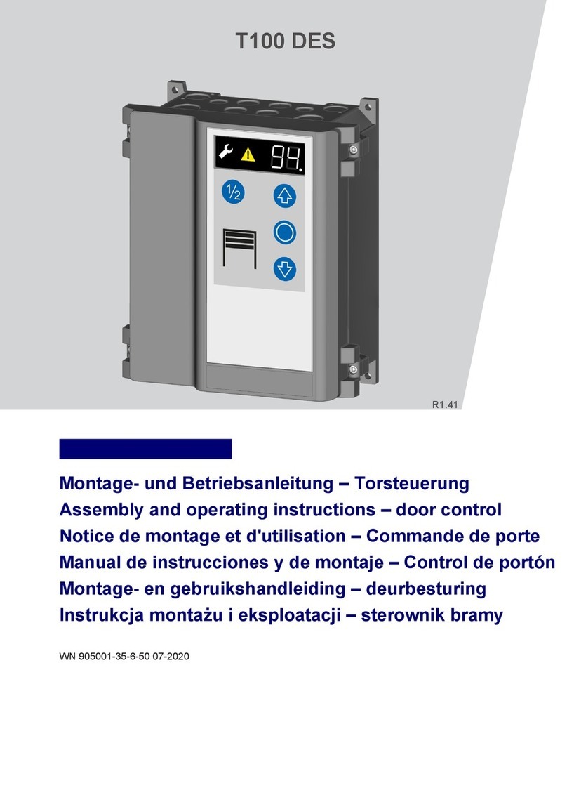
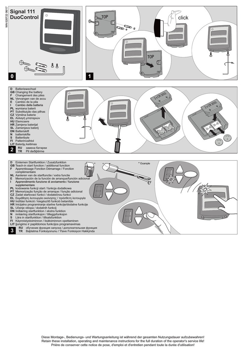
Tormatic T 100 DES Service manual

T 100 DES
GB Mounting and operating
instructions
0
T 20 23
6mm
182 mm
242 mm
1400 mm
1
2
13
12
WN 905001 08/11

24V DC
200 mA
24V DC
200 mA
3
Overview of connections
GB

1.1
X3
1.1
PE
L1 L2 L3 N PE
3 x 400V, N, PE
4a
U1 V1 W1
U2 V2 W2
M
3 ~
~ +
~-
1.1
1.1
1.1 1.1
1.1
1.1
1.1
1.2 1.1
1.1
1.1
1.1
1.3 1.1
1.1
1.1
1.1
1.4
N
W
PE
V
U
1.1
X1
X3
1.1
PE
L1 L2 L3 PE
3 x 230V, PE
4b
U1 V1 W1
U2 V2 W2
M
3 ~
G1
Y1
~ +
~-
1.1
1.1
1.1 1.1
1.1
1.1
1.1
1.2 1.1
1.1
1.1
1.1
1.3 1.1
1.1
1.1
1.1
1.4
N
W
PE
V
U
X1 G1
Y1
J9
1 2 3
4 5 6
1 2 3
4 5 6
X7
W V U N PE
N
W
PE
V
U
4
3
PE
2
1
3 2 1 4 PE
1-
2- RS485 A
3-
4- 12
5- 24V DC
6-
GND
24V DC
V DC
RS485 B
T °C
5
1.1
1.2
1.3
J1
1.4
1.1
1.2
1.3
J1
1.4
1.1
1.2
1.3
J1
1.4
NC
NO
NO
6b
6a 6c
1.1
X1
X3
1.1
PE
L1 N PE
1 x 230V, N, PE
4c
U1 UZ2 Z1
M
1 ~
1.1
1.1
1.1 1.1
1.1
1.1
1.1
1.2 1.1
1.1
1.1
1.1
1.3 1.1
1.1
1.1
1.1
1.4
N
PE
U
C1
J7
7.1
7.2
6d

21
22
4.1
4.2
4.3
J4
4.4
2.1
2.2
2.3
J2
2.4
1 2
LS 2
1 2
LS 2
1 2
LS 2
1
LS 2 LS 2LS 2LS 2
1 2
2.1
2.2
2.3
J2
2.4
8.6
8.7
X8
+V -V NC C NO
1 2 3
LS 5 LS 5
3.1
3.2
3.3
J3
4.1
4.2
4.3
J4
4.4
wh
gn
br
1
6
3.1
3.2
3.3
J3
4.1
4.2
8K2
4.3
J4
4.4
gn
br
1
6
1
2
3
4
5
6
gn
br
3.1
3.2
3.3
J3
4.1
4.2
4.3
J4
4.4
gn
br
1
6
1
2
3
4
5
6
DW
7.1
7.2
J7
0 I
9
8a
7a
10
8b
7b
8d
gn
br
1
2
3
4
5
6
wh
gn
br
8K2
11
1.1
X5
5.2
5.1 5.3 1.1
X6
6.2
6.1 6.3
10b
X8
8.6
8.7
24V
GND
24V
max. 200mA
24VDC
max.
1A
24V
12b
1.1
X5
5.2
5.1 5.3 1.1
X6
6.2
6.1 6.3
X2
N L
1.1 2.2
2.1
230V
max. 2A
230V
max. 2A
12a
2.1
2.2
2.3
J2
2.4
RLK 29
~/0V
~/+UB
7c
3.1
3.2
3.3
J3
4.1
4.2
8K2
4.3
J4
4.4
gn
br
1
2
3
4
5
6
8c

D
GB
ES
NL
Einstellungen obere [30] und untere [31] Torendlage
Setting the door's top [30] and bottom [31] end-of-travel position
Réglage de la position de fin de course supérieure [30] et
inférieure [31] de la porte
Configurar la posición superior [30] e inferior [31] final de la puerta
Instellen van de bovenste [30] / onderste [31] eindpositie van de deur
Ajuste da posição final superior [30] / inferior [31]
Impostazione posizione finale superiore [30] / inferiore [31] del portone
Indstilling øverste [30] / nederste [31] port-stoppunkt
Inställning av portens övre [30] / undre [31] slutposition
Innstilling øvre [30] / nedre [31] portendestilling
Nastavení horní [30] / spodní [31] koncové polohy vrat
FR
PT
I
DK
SE
N
CZ
FIN
Nastawy górnego [30] i dolnego [31] położenia krańcowego bramy
Oven ylä- [30] ja alaraja-asennon [31] säädöt
PL
1x
1x
5 x
1x
1x
5 x5 x
1x
1x 1x
5 sec.
1x
1x
5 x
1x
1/2
1x
EXIT
1/2
D
GB
ES
NL
Einstellen 1/2 Toröffnung [32]
Setting the door to the half-open
position [32]
Réglage de la 1/2 ouverture de porte [32]
Configuración de ½ apertura de la puerta [32]
Instellen deur half open [32]
Ajuste da abertura parcial do portão (½) [32]
Impostazione apertura portone a metà [32]
Indstilling ½ portåbning [32]
Inställning av en ½ portöppning [32]
Innstilling ½ portåpning [32]
Nastavení ½ otev [32]
Nastawianie ½ otwarcia bramy [32]
FR
PT
I
DK
SE
N
CZ
FIN
ření vrat
Oven säätö [32] puoleksi auki
PL
2x
1x
1x
EXIT

+~80mm
-~80mm
1x 1x
5 x
3x
1x 1x
D
GB
NL
DK
Feineinstellung Torendlage oben [33] und unten [34]
Fine adjustment of the top [33] and bottom [34] end-of-travel
position
Réglage précis de la position de fin de course supérieure [33] et
inférieure [34]
Fijn instellen van de bovenste [33] / onderste [34] eindpositie van de deur
Ajuste preciso da posição final superior [33] / inferior [34]
Microregolazione posizione finale superiore [33] / inferiore [34] del portone
Finindstilling øverste [33] / nederste [34] stoppunkt
Fininställning av den övre [33] / undre [34] slutpositionen
Fininnstilling øvre [33] / nedre [34] endestilling
[33] / [34]
Oven ylä- [33] ja alaraja-asennon [34] hienosäätö
FR
ES
PT
I
SE
N
CZ
FIN
PL
Configuración precisa de la posición final superior [33] e inferior [34]
Přesné nastavení horní spodní koncové polohy
Nastawa dokładna położenia krańcowego bramy u góry [33] i u dołu [34]
+~80mm
-~80mm
+~80mm
-~80mm
+~ max. 80mm
-~ max. 80mm
1x
+~ max. 80mm
-~ max. 80mm
+~80mm
-~80mm
1x
EXIT
1x
5 x
*
*
EXIT
5x 1x
5 x
1x
1x
1x
5 x
1x
1x
1x
2
8k2
OSE
44
2
8k2
OSE
1x
D
GB
NL
Auswahl Schließkante J3 [35] / Auswahl Licht-
schranke J4 [36]
Selecting the closing edge J3 [35] / Selecting the
photocell J4 [36]
Sélection du profil de sécurité optique J3 [35] et de la
photoélectrique J4 [36]
Selección de los cantos de cierre J3 [35] y de la barrera
fotoeléctrica [36]
Keuze van de sluitkant J3 [35] / Keuze van de fotocel J4 [36]
Selecção do perfil de fecho [35]/ da barreira fotoeléctrica [36]
Selezione del bordo di chiusura [35] / della fotocellula [36]
Val av tillslutningskant [35] / Val av fotocell [36]
Valg av lukkekant [35] / Valg av fotocelle [36]
3 [35]/
FR
ES
PT
I
DK
SE
N
CZ
FIN
barrière
Valg af lukkekant J3 [35] / Valg af fotocelle J4 [36]
Výběr uzavírací hrany [35] / Výběr optické závory [36]
Wybór krawędzi zamykającej J Wybór zapory świetlnej J4 [36]
Sulkureunan J3 [35] valinta/valokennon J4 [35] valinta
PL
*
*
*
4
4
2
2

EXIT
D
GB
ES
NL
PT
I
DK
Funk Start einlernen [60], Teilöffnung einlernen [61]
[60], [61]
Programming radio control of the START button [60],
programming radio control of partial opening [61]
Apprentissage du code radio de la touche de démarrage [60],
apprentissage radio de l'ouverture partielle [61]
Aprendizaje de la tecla de inicio del control remoto [60], aprendizaje de la
apertura parcial del control remoto [61]
Draadloze starttoets leren
Memorização da tecla de arranque por radiofrequência [60], da abertura
parcial por radiofrequência [61]
Radio: apprendimento del tasto di avvio [60], radio: apprendimento
dell'apertura parziale [61]
Indkøring trådløs startknap [60], indkør trådløs delåbning [61]
Inlärning radio startknapp [60], inlärning radio delöppning [61]
Lære inn trådløs startknapp [60], lære inn trådløs delåpning [61]
Zaprogramowanie startu ra
FR
SE
N
CZ
FIN
Draadloos gedeeltelijk openen leren
Programování tlačítka Start rádiového ovládání , programování
rádiem ovládaného částečného otevření [61]
[60]
diowego [60], zaprogramowanie otwarcia
Radiokäynnistyksen ohjelmointi [60], asennon osittain auki ohjelmointi [61]
PL
1/21/21/2
3sec
1x
5 x
3sec
5 x
1x
1x 1x
EXIT
1x
1x
1x
5 x
D
GB
NL
Abschaltposition Schließkantensicherheit [37]
Cut-off point of the safety edge [37]
Position de désactivation de la sécurité de contact
optique [37]
Posición de desconexión de la protección contra accidentes [37]
Afschakelpositie sluitkant [37]
Posição de corte da protecção do perfil de fecho [37]
Posizione di disattivazione costola di sicurezza [37]
Udkoblingsposition lukkekantsikring [ 37]
Frånkopplingsposition slutkantssäkring [37]
Utkoblingsstilling lukkekantsikring [37]
Pozice vypnutí jištìní uzávìrových hran [37]
FR
ES
PT
I
DK
SE
N
CZ
FIN
Pozycja wyłączania bezpieczeństwa krawędzi zamykającej
Turvareunavarmistimen katkaisukohta [37]
PL
7x
1x
1x
+~ max. 50mm
-~ max. 50mm
**
1x
5 x
1x
1x
EXIT
max. 50mm
max.~150mm
D
GB
NL
Abschaltung > 50mm - En12543 / EN2445 nicht erfüllt, Verlust Zulassung
Cut-off > 50 mm - EN12543/EN2445 not met, loss of approval
Désactivation > 50 mm - En12543 / EN2445 non satisfaites, perte de
l'homologation
Desconexión > 50 mm; no se cumple la norma En12543 / EN2445,
pérdida de la autorización
Afschakelen > 50 mm – niet voldaan aan EN12543 / EN2445, niet meer
goedgekeurd
Corte > 50 mm – Norma EN 12543 / EN 2445 não satisfeita, perda de
homologação
Disattivazione > 50 mm - EN12543/EN2445 non rispettata, erdita
dell'omologazione
Frånkoppling > 50 mm - EN12543/EN2445 inte uppfyllt, förlust av
godkännande
Utkobling > 50 mm - EN12543/EN2445 ikke oppfylt, mister godkjennelse
V
FR
ES
PT
I
DK
SE
N
CZ
FIN
Udkobling > 50 mm – En12543 / EN2445 ikke opfyldt, tab af tilladelse
ypnutí > 50 mm - En12543/EN2445 nesplněno, ztráta certifikace
Wyłączenie > 50 mm –En12543/En2445 niespełnione, utrata
dopuszczenia
Katkaisu > 50 mm - standardit EN12543/EN2445 ei täytetty, hyväksynnän
menetys
PL

T100 DES
Table of contents
• General Information
• Installation
• Operating instructions / Description of
functions
• Maintenance / Checks
- Safety
- Explanation of the symbols
- Working safety
- Spare parts
- Changes and modifications to the product
- Data plate
- Packaging
- Technical data
- Hazards that may emanate from the product
- Safety regulations
- Inspection and Test Log Book for the Door
System
- Check List of the Door System
- Proof of Inspection and Maintenance of the
Door System
- Declaration of Conf
• Programming overview
• Error Diagnosis
• Terms of Guarantee
• Inspection log book
ormity and Installation
• General Information
!
•
•
•
•
Safety
Explanation of the symbols
Working safety
Hazards that may emanate from the product
•
Before commencing any work on the product,
carefully read through the operating instructions
from start to finish, in particular the section entitled
“Safety”and the related safety advice. It is important
for you to have understood what you have read. This
product could prove hazardous if not used properly
as directed or in accordance with the regulations.
Any damage occurring as a result of non-compliance
with these instructions shall render the manufactu-
rer’s liability null and void.
WARNING: imminent danger
This symbol indicates that instructions are
being given which, if not observed, could
lead to malfunctions and/or failure of the
operator.
WARNING! Danger by electric current
The works may only be executed by an
electrician.
This symbol indicates that instructions are
being given which, if not observed, could
lead to serious injury.
Reference to text and figure
By complying with the safety advice and information
provided in these Operating Instructions, injury to
persons and damage to property whilst working on
and with the product can be avoided.
Failure to observe the safety advice and information
provided in these Operating Instructions as well as
the accident prevention and general safety
requirements relevant to the field of application shall
exempt the manufacturer or ist authorized
representatives from all liability and shall render any
damage claims null and void.
The product has been subjected to a risk assess-
ment. The design and execution of the product
based on this corresponds to state-of-the-art
technology.
When used properly as intended, the product is safe
and reliable to operate.
Nevertheless, a residual risk will always remain!
The product runs on a high electrical voltage. Before
commencing any work on electrical systems, please
observe the following:
1. Disconnect from the power supply
2. Safeguard to prevent a power restart
3. Check that the electricity supply is cut off.
Safety regulations
The following standards and regulations must
be observed:
When performing installation work, initial operation,
maintenance jobs or testing the control unit, take
care to observe the local safety regulations!
European standards
- DIN EN 12445
Safety in Use of Power-operated Doors and
Gates - Test Methods
- DIN EN 12453
Safety in Use of Power-operated Doors and
Gates - Requirements
- DIN EN 12978
Protective Devices for Power-operated Doors and
Gates - Requirements and Test Methods
0
In addition to the above, the normative references
of the standards listed must be observed.
- DIN EN 418
Safety of Machinery
Emergency-STOP device, functional aspects
Design principles
- DIN EN 60204-1 / VDE 0113-1
Electrical installations with electrical equipment
- DIN EN 60335-1 / VDE 0700-1
Safety of household and similar electrical
appliances
Dimensions of housing
Height x width x depth
250mm x 215mm x 120mm
Mounting vertical
Number of cable lead-throughs
6 x M20,
2 x M16,
2 x M20 V-cutout
Supply voltage
3 x 400 V AC
3 x 230 V AC
Control voltage
24 V DC
Max. motor output
max. 3.0 kW
Protection classification
IP 54, optional IP 65
Operating temperature
- 20°C to + 55°C
VDE regulations
•
•
•
•
Spare parts
Changes and modifications to the product
Data plate
Packaging
Only use genuine spare parts of the manufacturer.
Wrong or faulty spare parts can cause
damage, malfunctions or even a total failure
of the product.
In order to prevent hazards and ensure optimum
performance, no changes, modifications or
conversions may be made to the product that have
not been expressly approved by the manufacturer.
The date plate is located under the control panel
cover. Observe the specified power rating.
Always dispose of the packaging in an environ-
mentlly-friendly manner and in accordance with the
local regulations on disposal.
Manufacturer:
Novoferm tormatic GmbH
Oberste-Wilms-Str. 15a
D-44309 Dortmund
Technical Data
GB
12
Retain these installation, operating and maintenance instructions for the full duration of the operator’s service life!
WN 905001 05/11

Installation
J1 START / impulse input
(OPEN / STOP / CLOSE)
J2 Safety photocell, two or four-wire
J3 Closing edge OSE / 8K2 / DW
J4 Emergency-STOP, slack cable, latching
J7 Key switch, pull button
J9 Digital limit switch - motor cable
J10 Connection of add-on controls
J11 Connection of radio receiver
J12 Aerial
J13 Membrane keypad
X1 Mains connection
X2 Mains output L, N (500 W / 230 V)
X3 Protective conductor contact
X5 Floating relay contact 1,
door status relay
X5 Floating relay contact 2,
door status relay
X7 Door operator
X8 24V DC, 200mA
The control unit comes ready-wired with a 16A CEE
phase-changer plug and approx. 1 m of cable (see
.
The connecting lead for the motor and digital limit
switch (DES) is pre-assembled and ready to use -
attach accordingly.
If the gate is to be opened and closed by way of a key
(Open-Stop-Closed), select the following:
Set value 1 in menu 51 or
Menu 50, factory setting
The photocell must be correspondingly set/adjusted
in menu 36.
Two-wire photocell LS2
During this process the closing
procedure must not be interfered with,
otherwise the wrong position could be
recorded.
Four-wire photocell LS5 with self-testing
Reflection photocell RLK29
If in the menu the frame-fitted photocell has been
selected, the next time the door closes the control
unit automatically initiates a learning run to detect
the position.
When using impulse control for door closing,
connection of a safety edge is required. Select the
corresponding setting in menu 35.
Optical closing edge OSE
Electrical safety edge 8K2 with a termination
resistor of 8.2 kOhm
Pressure wave edge and switch with a loop
resistance of 8.2 kOhm
Required tools
Installing the control unit
Opening the control unit cover
Designation:
4a)
Motor connecting lead
Impulse generator connection
6c
6d
Photocell connection
7a
7b
7c
Safety edge connection
8a
8b
8c
8d
Emergency-STOP connection
Key switch / pull button connection
Connections
Mains connection
The unit must be connected to the mains in
accordance with the existing power supply
voltage.
Electrical safety edge 8K2 in series connection
with slack rope and wicket door switch
!
0
1
2
3
4
5
6
7
8
9
10
When using a key switch / pull button, the desired
function in menu 50 should be selected.
Plug in receiver module (option) at J11 and initiate
the hand transmitter learning procedure in menu 60,
61 or 62.
2 change-over contacts:
max. 250VAC / 2A or 24VDC / 1A.
24V-output X8: max. 200mA
Selecting the relay function in menu 45 and 46.
If the AR mode has been selected in menu 40 (menu
3 or 4), the function early warning light will be
assigned to X6. The settings in menu 46 will be
ineffective.
The programming is menu-driven. Carry out
adjustment of the door in accordance with the
scheme. The following page shows the full extent of
the menu.
(menus
30 and 31)
The door must be spring balanced.
Compensates changes in the closed position
resulting from temperature fluctuations, gearbox run-
in etc.
Compensates changes in the closed position
resulting from cable elongation or a rise
in the floor level. Set the precise closed position
beforehand, then set in menu 43.
If the set value is exceeded, error E32 is displayed.
After the springs have been renewed,
the door end-of-travel positions need to be reset.
Motor 9.24/5.24: input value = U x weight / 20 kg
Motor 9.20: input value = U x weight / 16 kg
Motor 9.15: input value = U x weight / 15 kg
Motor 9.24, U = 8 revolutions to open the door
Weight of the door leaf = 150 kg, each of the 2
springs bears 75 kg. Cut-off recommended at 60 kg.
= 8 x 60 kg / 20 kg =
The quick release requires re-setting,
otherwise spring fracture safeguards
must be connected.
Press the button of menu 47 for 5 sec rather than
only briefly, after the door has been completely
opened and closed once.
The value indicates how the door is balanced:
Motor 9.24/5.24: F (kg) = display value x 20 kg / U
Motor 9.20: F (kg) = display value x 16 kg / U
Motor 9.15: F (kg) = display value x 15 kg / U
U = number of revolutions for one door opening
If the display value ranges between -2 and -9, the
springs are over-tensioned.
The results are only approximate values; a force
measuring run is required to determine the value
more precisely.
The door's opening movements are compared with
one another. If the set value is exceeded, the door
stops and F33 is displayed.
Thereafter, the door can only be closed via the
dead man's control. Eliminate the reason
for the excessive force being applied, so that
the door can be opened and closed again.
Motor 9.24/5.24: input value = U x weight / 20 kg
Radio remote control
Relay output
Setting the door end-of-travel positions
Correcting the slowing-down path (menu 42)
Level adjustment (menu 43)
Spring breakage detection (menu 47)
Example:
Input value 24
Check of the spring balancing device
Opening force limit (menu 48)
Programming the control unit
!
!
!
11
12
GB
!
Motor 9.20: input value = U x weight / 16 kg
Motor 9.15: input value = U x weight / 15 kg
The results are only approximate values; a force
measuring run is required to determine the value
more precisely.
When using 6.65DU, the function will be
different. Please refer to section “DU
Functions” for more details.
to determine the cut-off
threshold. After value 99 has been entered in menu
48, the control will carry out a force measuring run:
1. Attach a test weight (recommended approx. 20
kg) at the door and open and close the door
completely.
2. Following that, menu 48 displays the value
which will be imported as cut-off value. This
value can be modified (double value equals
double force).
3. Remove the test weight again and open and
close the door.
The ON period set will prevent the drive motor from
getting overheated and thus getting damaged.
When using motor 5.24 with plastic transmission,
set the ON period at 1 (3~) or 2 (WS, 1~).
input J1.3 was used to generate a closing
impulse, J1.4 to generate an opening impulse.
The gate must remain visible from
the place of operating it.
inputs are used for OPEN-STOP-CLOSE.
J.1.3 for half-opening of the door, J1.4 for full
opening of the door.
Please note that each hand transmitter must be
individually programmed. It is possible for up to 30
radio codes to be learned. The following functions
can be taught in.
KeeLoq, 12 Bit Multibit. The first code determines the
type.
The various control types can be selected from menu
59. Please refer to the supplementary sheets for the
settings.
Enter the menu and press the button on the hand
transmitter for the START function. As soon as the
code has been learned, the incremental display
flashes five times.
Enter the menu and press the button on the hand
transmitter for the half-open position. As soon as the
code has been learned, the incremental display
flashes five times.
Enter the menu and press the button on the hand
transmitter for the light function. As soon as the code
has been learned, the incremental display flashes
five times.
To delete all the learned codes in the menu, press the
oval button and keep it pressed for 5 seconds.
Reset the control in menu 99 to the factory setting
during the commissioning. The function “Opening
force limit” in the DU can be selected from menu 48:
value = 0, force limit within
value = 1 …99, force limit has been activated
In order to protect the drive against overheating,
set the operating time to 5 in menu 49.
Force measuring run
ON period (menu 49)
External command units / impulse generators
(menu 51)
0
1
Programming the radio remote control
Selection of the control type (menu 59)
Start impulse (menu 60)
Half-open position of the door (menu 61)
Light function (menu 62)
Deleting radio codes (menu 63)
DU Functions (main menu 7)
!
!

Red traffic light with 3 seconds early warning phase
Red traffic light without early warning phase
Wipe impulse ELTACO
Hand transmitter on / off
5 minutes garage light
2 minutes garage light
Door open signal
Door closed signal
X5Status relay
Selection
3
2
5
4
3
2
1
0*
Entry
45
Menu-
point
Door open signal
Door closed signal
Status relay X6
1*
0
46
No.
4
Extended door settings
Red traffic light with 10 seconds early warning phase
4
120
90
60
50
40
30
20
10
0
Hold-open phase in seconds
Level adjustment
on
off
Correcting the slowing-down path
Partial reversing
Full reversing
Response of safety edge
Open-Close-operation/Red-green-traffic light A800 (option)
AR - shortened response time
AR - automatic closing
Impulse OPEN / Impulse CLOSE
Impulse OPEN / Dead man COSE
Dead man OPEN / Dead man CLOSE
Selecting the operating modes
0... 100mm higher
0... 50mm deeper
Adjustment pre-limit switch safety edge
Frame fitted photocell LS2
4-wire photocell LS5, Reflection photocell
2-wire photocell LS2
without photocell
Selecting the photocell
Pressure wave edge DW with testing
Electrical safety edge 8K2
Optical closing edge OSE
Selecting the closing edge
0... 80mm higher
0... 80mm deeper
Fine adjustment of top end-of-travel position
Setting the door's half-open position
Setting the door's bottom end-of-travel position
Change of direction (press for 5 sec.)
Setting the door's top end-of-travel position
Selection
8
7
6
5
4
3
2
1
0*
1*
0
1
0*
5
4
3
2*
1
0
25 - 99
25 - 0
25*
3
2
1
0*
2
1
No.
3
Basic door settings
0*
50 - 99
50 - 0
50*
Entry
40
37
36
33
32
31
30
Menu
point
0... 80mm higher
0... 80mm deeper
Fine adjustment of bottom end-of-travel position
50 - 99
50 - 0
50*
34
41
42
Exit menu
- -
35
Input spring force
off
Spring breakage detection
1 - 99
0*
47
Input cut-off force
off
Opening force limit
1 - 98
0*
48
D 14.15 25 min / 60 %rive motor
D 9.24 WS 25 min / 20 %rive motor4
2
D 5.24 25 min / 35 %rive motor
Without limitation
Motor starting time
1
0*
49
D 6.65 DU 10 min / 35 %rive motor
5
6
D 5.24 WS 25 min / 30 %rive motor
3D 9.15, 9.20, 9.24 25 min / 60 %rive motor
Photocell LS5, frame fitted reflection photocell4
Display spring balance (press 5 sec.)
Carry out weight measuring run with test weight99
9
12
11
10
150
240
210
180
44
Programming Overview GB
1x
3-9 30-
37
Exit
EnterMenu Item
43
1
0*
2
activated for 200 cycles
off
activated for 1,000 cycles
4
* Factory defaults
Like 5, but with a reduction at the light barrier6
Exit menu
- -
Extended door settings
2-wire photocell with stop during Open/Close
5
4-wire photocell with stop during Open/Close6

Selection
Entry
Menu-
point
No.
Resetting of factory setting (press for 5 sec.)
Issue of software version-serial-no. date- - -
Issue of error memory hours error code- - -
Issue of operating hours counter hours- -
cycles- -Issue of cycles counter
50000 cycles
45000 cycles
40000 cycles
35000 cycles
30000 cycles
25000 cycles
20000 cycles
16000 cycles
12000 cycles
8000 cycles
4000 cycles
1000 cycles
no service interval
Selecting the door's service intervals
12
11
10
9
8
7
6
5
4
3
2
1
0*
90
Exit menu
Service menu
91
96
97
98
99
- -
9
* Factory defaults
Programming Overview GB
1x
3-9 30-
37
Exit
EnterMenu Item
7
DU- settings
Increased closing speed
Speed in rpm
Closing speed
Speed in rpm
Opening speed
0*
20 - 30
20*
20 - 65
30*
71
72
73
Door setting change-over point to[73] [72]
Speed in rpm20 - 30
74
Acceleration time close
x 0.1 sec
Acceleration time open
20*
05 - 30
20*
75
76 x 0.1 sec05 - 30
Braking time close
x 0.1 sec
Braking time open
20*
05 - 30
20*
77
78 x 0.1 sec05 - 30
- - Exit menu
Exit menu
Exit menu
Deleting radio codes (press for 5 sec.)
Programming the light button on the transmitter
Programming button for 1/2-opening on the transmitter
Programming the START button on the ransmitter
Expansion control
without expansion control
Selection
No. Entry
Menu-
point
- -
660
61
62
63
- -
Radio
54 0*
Half opening of the door only
Operating mode impulse OPEN / dead man CLOSE
Activating the control elements for 10 secs.
Block control panel and external control elements
Block external control elements
Block control panel
Impulse transmitter Open-Stop-Close
Key switch function (J7)
6
5
4
3
2
1
0*
50
5
Miscellaneous settings
Open-Stop-Close function (J1.3 1/2-opening J1.4 full-opening)
Function of external impulse generators
1
51 Three-button-control
0*
Entering the control address
DC-module
-
52
53 without DC-module
0*
- - Exit menu
(press for 5 sec.)Selection of the control type
T100 DES
59
18
T100 NES
T100 NES with stop command
19
20
T100 DES-H height detection
21

Operating instructions /
Description of function
The control unit allows a variety of operating modes:
Pressing button and keeping it pressed causes the
door to open until the OPEN end-of-travel position is
reached. Releasing the button causes the door to
stop. The door is closed by dead man's control, i.e.
pressing button and keeping it pressed, until the
door reaches its CLOSE end-of-travel position. If the
button is released during closing, the door stops
instantly.
By briefly pressing the button or generating an
impulse from an external impulse generator, the door
starts to open until reaching the OPEN end-of-travel
position or the door can be stopped beforehand by
pressing button . If button is pressed again, the
door continues to open. The door is closed by dead
man's control, i.e. pressing button and keeping it
pressed, until the door reaches its CLOSE end-of-
travel position. If the button is released during
closing, the door stops instantly.
By briefly pressing button or generating an impulse
from an external impulse generator the door starts to
open until reaching the OPEN end-of-travel position,
or the door can be stopped beforehand by pressing
button . By briefly pressing button the door starts
closing until reaching the CLOSE end-of-travel
position.
This operating mode demands that a safety edge
(menu 35) be installed. If the safety edge is triggered
during closing, the door stops and changes direction.
If the safety edge is triggered during opening, this has
no effect. In the case of a defect, the door can be
closed by pressing button .
By briefly pressing button or generating an impulse
from an external impulse generator, the door starts
opening until reaching the OPEN end-of-travel
position. Or the door was stopped prematurely using
button . Once the set hold-open time has elapsed,
there follows an early warning phase of 10 seconds,
after which time the door automatically closes.
If button is pressed when the door is in the open
position or while it is closing, the door is immobilized
until a new impulse or is generated.
If menu 36 has been set to 5 or 6, the gate will stop
during its travel. Subsequently, the hold-open time
will re-start.
Function as described above, but an interruption of
the photocell causes the set hold-open time to be
terminated and the early warning phase to begin.
After the early warning phase has expired, the door
automatically closes.
However, the receiver remains plugged into the drive
in the same operating mode like the one-way control
with the red-green traffic light (optional traffic light
controlA800).
Operating sequence for external impulse generators:
Drive starts and moves the door into the open
position
Door continues to move without being affected
Door closes
Dead man OPEN / dead man CLOSE
Impulse OPEN / dead man CLOSE
Impulse OPEN / impulse CLOSE
AR-mode / automatic closing
AR-mode with shortened response time via
photocell
OPEN-CLOSE operation
Generating an impulse in the close position:
Generating an impulse during the opening:
Generating an impulse in the open position:
Generating an impulse during the closing:
First impulse:
Impulse generated during travel:
A new impulse is generated:
An impulse is generated:
Door stops and opens again
Pressing the ½ button initiates the set half-opening of
the door (menu 32).This function is not available in
the dead man OPEN / dead man CLOSE operating
mode.
The control unit has two relay outputs allowing the
switching of lighting or the early warning light (menu
45 and 46).
The control unit has an input for a key switch. This
allows you to activate the following functions (menu
50):
Impulse transmitter Open-Stop-Close
Control panel on the control unit is
blocked.
All external control elements are
blocked.
Control panel on the control unit and all
external control elements are blocked.
For 10 secs. the control panel on the
control unit and all the external control
elements are active.
Switching of operating mode to impulse
OPEN / dead man CLOSE.
Half-opening of the door only.
The door can be opened and closed via external
command units/impulse generators.
Button: Start
The operator starts up and causes the door to travel
to the set OPEN or CLOSE travel limits.
Door stops.
Door continues to travel but in the opposite direction.
AR-function:
Door opens.
½ button for half-opening:
Function as with the START button, but the door
travels to the set half-open position only.
Button: Light
The light function involves a continuous light that can
be switched on/off independent of the door action.
Half-opening of the door
Lighting and / or early warning light
Key switch function (optional)
0
1
2
3
4
5
6
External command units / impulse generators
Radio hand transmitter (optional)
Maintenance / Checks
Service display
If the control unit establishes the need for testing /
inspection, "service" shows up in the display. Contact
a specialist company.
For your own safety, we recommend
that prior to initial operation and
whenever required - however at least
once a year, you have the door system
tested by a specialist company.
GB

Error Diagnosis GB
Subject to changes
Terms of Guarantee
Error State Diagnosis / Remedy
E05 Door neither opens nor closes
E06 Door reverses / does not close Check menu setting [35].
E07 Door reverses / does not close .
E08 Door neither operns nor closes
E09 Door neither opens nor closes
E10
No response , exchange control unit.
No response , exchange control unit.
No response , exchange control unit.
No response
Door neither opens nor closes
Door neither opens nor closes
Motor not running
F31 Door neither opens nor closes
F32 Door neither opens nor closes
F33
Door neither opens nor closes
Door neither opens nor closes
F2 No response , exchange control unit.
F3
F4
F5
F06 Safety edges defective,
F07
F08
F10
F19
F20
Photocell
F21
F23
F24
F25
F26
F28
F29
F30
The slack cable switch has tripped (see Fig. 8c).
Closing edge has been triggered.
Photocell has been triggered. Check menu setting [36]
External safety device (emergency-STOP, slack cable, wicket door, motor's thermal
switch) has been activated. Check (J4).
No end-of-travel positions learned. Programme the end-of-travel positions [30] [31].
Menu 36 set at 3 or 4 Allow door to open and close fully in order for the position of the photocell to be detected.
Error occurred during self-testing
Error occurred during self-testing
Error occurred during self-testing
.
Door responds only to dead man's
control for closing
No connection to DES. Check motor connecting lead and DES.
End-of-travel positions shifted Check mechanics of both motor and door.
Check both motor and motor connecting lead.
Motor rotates in the wrong direction Mains phases have been exchanged; correct or reset.
Door responds only to dead man's
control for closing Returns from impulse to dead man's control. Check safety edges and photocell.
Button actuated. Continuous impulse operative. Check external command generators (J1).
Spring breakage detection has been activated. Check springs and if necessary replace and
programme the end-of-travel positions again.
Door stopped while opening Opening force limit activated. Thereafter, the door can only be closed via the dead man's
control. Eliminate sluggishness or blocking of door. Check springs. Eliminate the reason
for the excessive force being applied, so that the door can be opened and closed again.
F34 The ON period has been exceeded. Wait and let the motor cool down.
F35 The speed monitoring has tripped. Exchange DU drive.
F40 Expansion control The 24-V power supply has broken down. Check the connections at the expansion control.
F41 Expansion control Fault during the self-test. Replace the expansion control.
Error occurred during self-testing
Check voltage (J3.3 - J3.1 >12V).
The 24V power supply has broken down. Check the connections.
Extension module function defective Fault in the add-on controls. Check the add-on controls.
Door stops shortly after START
command given Malfunction in the control unit electronics. Replace control unit.
Door responds only to dead man's
control for closing Closing edge self-testing has failed. Check safety edge.
self-testing has failed. Check photocell.
Operation briefly interrupted Door operator's excess travel stop activated, allow operator to cool down for approx. 20 min.
No response to START command Door's end-of-travel positions defective. Check end-of-travel positions and if necessary re-
adjust.
No response to START command
No response Internal testing of membrane keypad defective. Replace membrane keypad.
No response Internal testing of external buttons / switches has failed.
No response to START command Fault in the voltage supply. Check mains connection.
Plausibility error of DES
We shall not bear the costs for dismantling
and installation, freight and carriage. If a
complaint is proven to be unjustified, the
customer must bear our costs.
This guarantee is only valid in conjunction
with the signed invoice and commences on
the day of delivery. The manufacturer
guarantees that the product is free of defects.
The warranty is granted for a period of 24
months, in as far as the verification overleaf
has been properly filled out. Otherwise the
warranty shall expire 27 months after the date
of manufacture.
alterations or modifications carried out to the
operator and accessory parts by the customer.
The same shall also apply for damage incurred
during transit or as a result of force majeure,
external influences or natural wear as well as
special atmospherical stresses. We cannot
accept any liability following alterations or
modifications of functional parts carried out by
the customer. We must be notified of any
defects immediately in writing; on request the
parts in question are to be made available to
us.
Dear customer,
During production the industrial door operator
you have purchased has undergone various
checks by the manufacturer to ensure that it is
of impeccable quality. Should this operator or
parts of it prove to be of no use or limited use
as a result of proven material or manufacturing
defects, we shall rectify this, at our discretion,
through free-of-charge repair or replacement.
We shall not accept any liability for damage as
a result of unsatisfactory fitting and
installation, improper putting into service,
incorrect operation and maintenance,
excessive use and overloading as well as any
Other manuals for T 100 DES
2
Other Tormatic Control Unit manuals
Popular Control Unit manuals by other brands
Holley
Holley pro-jection 2D Installation, Tuning, & Troubleshooting Manual
Velleman
Velleman Velbus VMB1BL manual
Bray
Bray FlowTek F15 Series Installation and maintenance manual
Speck
Speck UL50/1000Dr operating instructions

SmarTap
SmarTap e-Valve installation guide
PMFoundations
PMFoundations Buffered Multipl Assembly guide

