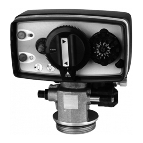
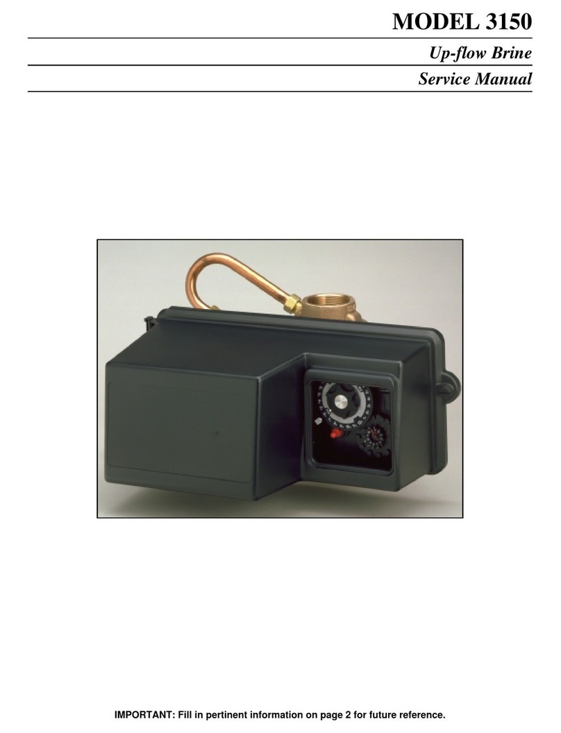
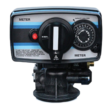
Fleck 9500 User manual

IMPORTANT: Fill in pertinent information on page 2 for future reference.
MODEL 9500
Service Manual

MODEL 9500 ECONOMINDER
Job Specification Sheet
Printed in U.S.A.
• JOB NO. __________________________________________________________
• MODEL NO. _______________________________________________________
• WATER TEST______________________________________________________
• CAPACITY PER UNIT ____________MAX. ___________PER REGENERATION
• MINERAL TANK SIZE DIA.________HEIGHT_________
• BRINE TANK SIZE &
SALT SETTING PER REGENERATION: _________________________________
Page 2
* 9500 CONTROL VALVE SPECIFICATIONS
1) Type of Timer
A) 82 minute available regeneration time, 1/15 RPM
B) 164 minute available regeneration time, 1/30 RPM
2) Type of Meter
A) Std. range 625 to 10,625 gal. setting
B) Ext. range 3,125 to 53,125 gal. setting
3) Meter Gallon Setting ____________________________gal. (see pages 6 & 7)
4) Regeneration Program Setting (see page 5)
A) Backwash _________________________________min.
B) Brine & Slow Rinse _________________________min.
C) Rapid Rinse _______________________________min.
D) Brine Tank Refill ____________________________min.
5) Drain Line Flow Control__________________________gpm
6) Brine Refill Rate________________________________gpm
7) Injector Size __________________________________

Printed in U.S.A.
Page 3
MODEL 9500 ECONOMINDER
General & Commercial Installation Checklist
WATER PRESSURE: A minimum of 25 pounds of water pressure is required for the valve to operate effectively.
ELECTRICAL FACILITIES: A continuous 110 volt, 60 Hertz current supply is required. Make certain the current supply
is always hot and cannot be turned off with another switch.
EXISTING PLUMBING: Condition of existing plumbing should be free from lime and iron buildup. Piping that is built up
heavily with lime and/or iron should be replaced. If piping is clogged with iron, a separate iron filter unit should be
installed ahead of the water softener.
LOCATION OF SOFTENER AND DRAIN: The softener should be located close to a drain.
BY-PASS VALVES: Always provide for the installation of a by-pass valve.
CAUTION: Water pressure is not to exceed 125 p.s.i., water temperature is not to exceed 110°F, and the unit cannot
be subjected to freezing conditions.
1. Place the softener tank where you want to install the unit, making sure the tanks are level and on a firm base.
2. All plumbing should be done in accordance with local plumbing codes. The pipe size for the drain line should be the
same size as the drain line flow control connection.
3. Both tanks must be the same height and diameter and filled with equal amounts of media The 1-1/2 distributor tube
should be cut flush with top of each tank.
4. Lubricate the distributor O-Ring seal and tank O-Ring seal with silicone lubricant. Place the main control valve on
one tank and the tank adapter on the second tank.
5. NOTE: The 1-1/2″copper tubing to interconnect the tanks must be soldered prior to assembly on the main control
valve and tank adapter.
6. Solder joints near the drain must be done prior to connecting the Drain Line Flow Control fitting. Leave at least 6″
between the DLFC and solder joints when soldering. Failure to do this could cause damage to the drain module.
7. Teflon tape is the only sealant to be used on the drain fitting.
8. Make sure that the floor is clean beneath the salt storage tank and that it is level.
9. Place approximately 1″of water above the grid plate (if used) in your salt tank. Salt may be placed in the unit at this
time.
10. On units with a by-pass, place in by-pass position. Turn on the main water supply. Open a cold soft water tap
nearby and let run a few minutes or until the system is free from foreign material (usually solder) that may have
resulted from the installation.
11. Place the by-pass in service position and let water flow into the mineral tanks. When water flow stops, open a cold
water tap nearby and let run until air pressure is relieved.
12. Electrical: All electrical connections must be connected according to codes. Plug unit into electrical outlet. Do not
insert meter cable into the meter yet.
INSTALLATION AND START-UP INSTRUCTIONS
1-1/2″COPPER
OUTLET
INLET METER DOME
MUST FACE UP
CONTROL VALVE
TANK #2
TANK ADAPTER
TANK #2

Printed in U.S.A.
Page 4
MODEL 9500 ECONOMINDER
General & Commercial Installation Checklist (Cont’d.)
13. Tank #1 has control
valve.
Tank #2 has the
adapter.
Look on the right side
of the control valve, it
has indicators which
tell you which posi-
tion the control valve
is in during regenera-
tion and which tank is
IN SERVICE. Photo
on the right indicates
the valve is in the ser-
vice position and tank
#1 is supplying condi-
tioned water. Tank #2
is on standby.
NOTE: Make sure the meter cable is not inserted in the
meter dome. Swing the timer out to expose the program
wheel Figure 2 (to swing timer out) grab onto the lower
right corner of timer face Figure 1 and pull outward.
14. Cycle timer into backwash position. Turn manual knob
(figure 1) so that the micro switch is riding on the 1st
set of pins (figure 2). In this position the tanks will
switch (lower piston) and the control valve will move
to the backwash position (upper piston). You must
wait until the positioning of upper and lower pistons
has stopped before advancing the timer further. If
advanced too fast the control will not home into the
service position (it will not advance to any other
position). To correct this, rotate the manual knob back
to service and start again into backwash. Note: once
valve has positioned itself into the backwash cycle,
the homing circuit is locked in.
With all the air backwashed out, slowly cycle the timer
to the brine position; rapid rinse; and brine tank refill.
You must wait for the control drive motor to position
itself in each cycle and stop, before advancing on to
the next position.
Once back in the service position, cycle the control
valve again into the backwash position. The tanks will
switch again, and you will backwash the air head out
of the other tank. Cycle the control back to the service
position. Leave the timer in the open position.
DO NOT INSERT METER CABLE YET.
NOTE: 2 motors are available, 1/15 RPM will have a 82
min. reg. time available.
BRINE & RINSE
SECTION
(2 MIN. PER HOLE)
PIN STORAGE
PROGRAM
WHEEL FOR
CONTROL OF
REGENERATION
CYCLE
RAPID
RINSE
SECTION
(2 MIN.
PER PIN)
BRINE TANK
REFILL
SECTION
(2 MIN.
PER HOLE)
BACKWASH
SECTION
(2 MIN. PER PIN)
Figure 2

Printed in U.S.A.
Page 5
MODEL 9500 ECONOMINDER
Regeneration Cycle Program Setting Procedure
(Brine Tank Refill Separate From Rapid Rinse)
How To Set The Regeneration Cycle Program:
The regeneration cycle program on your water conditioner
has been factory preset, however, portions of the cycle or
program may be lengthened or shortened in time to suit
local conditions.
To expose cycle program wheel, grasp timer in lower right
hand corner and pull, releasing snap retainer and
swinging timer to the left. Meter cable must be removed
from meter dome before opening timer.
To change the regeneration cycle program, the program
wheel must be removed. Grasp program wheel and
squeeze protruding lugs towards center, lift program
wheel off timer. (Switch arms may require movement to
facilitate removal.)
Return timer to closed position engaging snap retainer in
back plate. Make certain all electrical wires locate above
snap retainer post
How To Change The Length Of The Backwash Time:
The program wheel as shown in the drawing is in the
service position. As you look at the numbered side of the
program wheel, the group of pins starting at zero deter-
mines the length of time your unit will backwash.
FOR EXAMPLE: If there are six pins in this section, the
time of backwash will be 12 min. (2 min. per pin). To
change the length of backwash time, add or remove pins
as required. The number of pins times two equals the
backwash time in minutes.
How To Change The Length Of Brine And Rinse Time:
The group of holes between the last pin in the backwash
section and the second group of pins determines the
length of time that your unit will brine and rinse. (2 min.
per hole.)
To change the length of brine and rinse time, move the
rapid rinse group of pins to give more or fewer holes in the
brine and rinse section. Number of holes times two
equals brine and rinse time in minutes.
How To Change The Length Of Rapid Rinse:
The second group of pins on the program wheel deter-
mines the length of time that your water conditioner will
rapid rinse. (2 min. per pin.)
To change the length of rapid rinse time, add or remove
pins at the higher numbered end of this section as
required. The number of pins times two equals the rapid
rinse time in minutes.
NOTE: Program wheels having 0 to 82 min. cycle times,
use “1” min. per pin or hole to set regeneration times. The
layout of pins and holes on the program wheel follow the
same procedure as on this page.
How To Change The Length Of Brine Tank Refill Time:
The second group of holes on the program wheel
determines the length of time that your water conditioner
will refill the brine tank (2 min. per hole.)
To change the length of refill time, move the two pins at
the end of the second group of holes as required.
The regeneration cycle is complete when the outer micro-
switch is tripped by the two pin set at end of the brine tank
refill section. The program wheel, however, will continue
to rotate until the inner micro-switch drops into the notch
on the program wheel. See page 6 for salt setting
calculations, and page 25 for general timer settings.
BRINE & RINSE
SECTION
(2 MIN. PER HOLE)
PIN STORAGE
PROGRAM
WHEEL FOR
CONTROL OF
REGENERATION
CYCLE
RAPID
RINSE
SECTION
(2 MIN.
PER PIN)
BRINE TANK
REFILL
SECTION
(2 MIN.
PER HOLE)
BACKWASH
SECTION
(2 MIN. PER PIN)
.

Printed in U.S.A.
Page 6
MODEL 9500 ECONOMINDER
Time Brine Refill & Meter Setting Procedure
PROGRAMMING
1. Your control valve has been factory set for backwash; brine and slow rinse; rapid rinse and brine tank fill times. Any
of these times can be changed by repositioning the pins and holes or adding more pins (see pg. 5). Note that two
different speed timer motors are used, one allows for an 82 minute maximum regeneration time (each pin or hole
=1 min.). The other allows for 164 minute maximum regeneration time (each pin or hole = 2 min.).
2. The 9500 Control has a separate brine tank fill cycle. Your desired salt setting must be calculated, using the brine
line flow control rate of refill (in gpm) times your timer setting. Then using one gallon of fresh water dissolving
approximately 3 lbs. salt, calculate your refill time.
ie: A desired 30 lb. salt setting: The unit has a 1.0 gpm refill rate, we will need a 10 gallon fill. (10 gal. x 3 lb./gal. =
30 lb. salt). The timer refill section would have to be set at 10 minutes. (10 min. x 1.0 gpm = 10 gal. fill)
Note: There always must be 2 pins at the end of your refill time. This is to stop the fill cycle. With your
regeneration times now set, place timer back to its original position, making sure the lower right hand
corner snaps back into the backplate and the meter cable slides through the backplate and does not bind.
3. Setting the gallon wheel
Knowing the amount of resin you have in each tank and your salt setting per regeneration, calculate the gallons
available, using the following capacities as a guide:
One Cubic Foot of Resin
Salt Setting at Capacity per Regeneration
15 lb 30,000 grains
10 lb 27,000 grains
8 lb 24,000 grains
6 lb 20,000 grains
ie: 35 grain water; each tank having 7 cubic feet of resin and salted at 56 lb. of salt, yielding a usable 168,000
grain capacity: 4,800 gallons available = 168,000 gr. capacity
35 gr. water
DO NOT SET THIS FIGURE - GO TO STEP 4
4. Since the 9500 Valve regenerates with soft water from the other tank, you must subtract the water used for
regeneration. Take each of your regeneration cycles and calculate the water used. (Use the injector Slow Rinse
rate chart supplied, see pg. 24.)
ie: Unit is set up for a 21 tank having 7 ft3of resin and salting at 8 lbs. per ft3, 12.0 gpm backwash, 4C injector, 2.0
gpm brine refill, and 60 psi and timer set up for 10 min. backwash, 42 min. brine and rinse, 10 min. rapid rinse,
10 min. brine tank fill.
A. Backwash - 10 mins. x 12.0 gpm = 120.0 gallons
B. Brine and Rinse - 42 mins. x 1.95 gpm = 81.9 gallons
(See injector chart slow rinse flow, pg. 24)
C. Rapid Rinse - 10 mins. x 12.0 gpm = 120.0 gallons
D. Brine Tank Fill - 10 mins. x 2.0 gpm = 20.0 gallons
Total Regeneration Water = 341.9 gallons
Gallons available = Capacity per Cubic Foot.
Compensated Hardness of H2Ox Cubic Feet of Resin per Tank

Printed in U.S.A.
Page 7
MODEL 9500 ECONOMINDER
Time Brine Refill & Meter Setting Procedure (Cont’d.)
If we have 4800 gallons available from Step 3, we want to subtract the regeneration water used from the total water
available.
4800 gallons available - 342 gallons used (in regeneration, step 4) = 4458 gallons setting
5. NOW set Meter wheel at approximately 4458 gallons. Lift the inner dial of the meter program wheel so that you can
rotate it freely. Position the white dot opposite the 4458 gallon setting (see diag. below).
NOTE: There is a slight delay time from the time the meter zeros out and when the cycle starts. Units using the 1/15
rpm motor, 82 minute regeneration time available have a 9 minute delay. Units using the 1/30 rpm motor,
180 minute regeneration time available have an 18 minute delay. Typically on residential equipment this
delay period is not critical. On commercial applications, this must be taken into consideration and
continuous flows for 9 minutes or 18 minutes should be subtracted from water available.
NOW 1. Insert Meter cable into Meter.
2. Check Bypass.
3. Plug unit in.

Printed in U.S.A.
Page 8
MODEL 9500 ECONOMINDER
1 - SERVICE POSITION
Hard water enters the unit at the valve inlet, flows
around the lower piston, and down through the mineral
in the first tank. Conditioned water enters the center
tube through the bottom distributor, flows up through
the center tube, around the lower piston, through the
meter, and out the valve outlet. The second mineral
tank is regenerated and on standby.
2 - TANKS SWITCHING
(the meter has initiated a regeneration)
Hard water enters the unit at the valve inlet, flows
around the lower piston, through the pipe leading to the
second mineral tank, and down through the mineral in
the second tank. Conditioned water enters the center
tube of the second tank through the bottom distributor,
flows up through the center tube, through the pipe
leading back to the main valve, around the lower piston,
through the meter, and out the valve outlet. The
depleted first mineral tank is out of the flow path, and
ready for regeneration.
BRINE VALVE
FLOW CONTROL
DRAIN
MINERAL TANK #1 BRINE TANK
BRINE VALVE
FLOW CONTROL
DRAIN
MINERAL TANK #1 BRINE TANK

Printed in U.S.A.
Page 9
MODEL 9500 ECONOMINDER
BRINE VALVE
FLOW CONTROL
DRAIN
MINERAL TANK #1 BRINE TANK
3 - BACKWASH
Conditioned water from the second mineral tank flows
around the lower piston, around the upper piston,
through the center of the lower piston, down the center
tube, up through the mineral, around the upper piston,
and out the drain line.
4 - BRINE DRAW
Conditioned water from the second mineral tank flows
around the lower piston, around the upper piston, into
the injector housing, and down through the nozzle and
throat to draw brine from the brine tank. Brine flows
around the upper piston, down through the mineral, into
the center tube through the bottom distributor, up the
center tube, through the center of the lower piston,
through the center of the upper piston, and out through
the drain line.
BRINE VALVE
FLOW CONTROL
DRAIN
MINERAL TANK #1 BRINE TANK

Printed in U.S.A.
Page 10
MODEL 9500 ECONOMINDER
5 - SLOW RINSE
Conditioned water from the second mineral tank flows
around the lower piston, around the upper piston, into
the injector housing, down through the nozzle and
throat, around the upper piston, down through the
mineral, into the center tube through the bottom
distributor, up the center tube, through the center of the
lower piston, through the center of the upper piston,
and out through the drain line.
6 - RAPID RINSE
Conditioned water from the second mineral tank flows
around the lower piston, around the upper piston, and
down through the mineral in the first tank. Rinse water
from the mineral bed enters the center tube through the
bottom distributor, flows up the center tube, through the
center of the lower piston, through the center of the
upper piston, and out through the drain line.
BRINE VALVE
FLOW CONTROL
DRAIN
MINERAL TANK #1 BRINE TANK
BRINE VALVE
FLOW CONTROL
DRAIN
MINERAL TANK #1 BRINE TANK

Printed in U.S.A.
Page 11
MODEL 9500 ECONOMINDER
7 - BRINE TANK FILL POSITION
Conditioned water from the second mineral tank flows
around the lower piston, around the upper piston, into
the injector housing, through the brine line flow control,
through the brine valve, and into to brine tank. No water
flows through the first mineral tank.
8 - SERVICE (TANKS SWITCHED)
Hard water enters the unit at the valve inlet, flows
around the lower piston, through the pipe leading to the
second mineral tank, and down through the mineral in
the second tank. Conditioned water enters the center
tube of the second tank through the bottom distributor,
flows up through the center tube, through the pipe
leading back to the main valve, around the lower piston,
through the meter, and out the valve outlet. The
regenerated first mineral tank is out of the flow path,
and ready for use when the second mineral tank
becomes depleted.
BRINE VALVE
FLOW CONTROL
DRAIN
MINERAL TANK #1 BRINE TANK
BRINE VALVE
FLOW CONTROL
DRAIN
MINERAL TANK #1 BRINE TANK

Printed in U.S.A.
Page 12
MODEL 9500 ECONOMINDER
Drive Assembly
(See Opposite Page for Parts List)
1
3
4
5
6
7
89
10
11
12
14
15
16 17 18 19 20
21
22
23
25
26
27
28 29
30
32
33
34
35
36
37
1
2
3
2
34
24
41

Printed in U.S.A.
Page 13
MODEL 9500 ECONOMINDER
Drive Assembly
Parts List
Item No. Quantity Part No. Description
1. . . . . . . . . . . . 2 . . . . . . . . . . . . .11335. . . . . . . . . . . . . . . . . . Screw
2. . . . . . . . . . . . 2 . . . . . . . . . . . . .18564. . . . . . . . . . . . . . . . . . Screw, Hex Washer, #6-20
3. . . . . . . . . . . . 2 . . . . . . . . . . . . .13363. . . . . . . . . . . . . . . . . . Washer
4. . . . . . . . . . . . 1 . . . . . . . . . . . . .14921. . . . . . . . . . . . . . . . . . Piston Rod Link, Upper
5. . . . . . . . . . . . 1 . . . . . . . . . . . . .15019. . . . . . . . . . . . . . . . . . Piston Rod Link, Lower
6. . . . . . . . . . . . 2 . . . . . . . . . . . . .18728. . . . . . . . . . . . . . . . . . Nut, Clip, #8-32
7. . . . . . . . . . . . 1 . . . . . . . . . . . . .15203. . . . . . . . . . . . . . . . . . Wiring Harness - Timer
8. . . . . . . . . . . . 1 . . . . . . . . . . . . .11838. . . . . . . . . . . . . . . . . . Power Cord
9. . . . . . . . . . . . 1 . . . . . . . . . . . . .15202. . . . . . . . . . . . . . . . . . Wiring Harness - Drive
10. . . . . . . . . . . . 1 . . . . . . . . . . . . .15134. . . . . . . . . . . . . . . . . . Drive Gear Assy, Lower
11. . . . . . . . . . . . 1 . . . . . . . . . . . . .15135-02 . . . . . . . . . . . . . . . Drive Gear Assy
12. . . . . . . . . . . . 1 . . . . . . . . . . . . .14896. . . . . . . . . . . . . . . . . . Geneva Wheel
14. . . . . . . . . . . . 4 . . . . . . . . . . . . .12681. . . . . . . . . . . . . . . . . . Wire Connector
15. . . . . . . . . . . . 2 . . . . . . . . . . . . .19367. . . . . . . . . . . . . . . . . . Cover Screw
16. . . . . . . . . . . . 1 . . . . . . . . . . . . .15175. . . . . . . . . . . . . . . . . . Position Decal
17. . . . . . . . . . . . 2 . . . . . . . . . . . . .14917. . . . . . . . . . . . . . . . . . Retaining Ring
18. . . . . . . . . . . . 1 . . . . . . . . . . . . .15199. . . . . . . . . . . . . . . . . . Ground Plate
19. . . . . . . . . . . . 1 . . . . . . . . . . . . .14430. . . . . . . . . . . . . . . . . . Screw, Hex Washer, #6
20. . . . . . . . . . . . 2 . . . . . . . . . . . . .19160. . . . . . . . . . . . . . . . . . Screw, Motor Mtg.
21. . . . . . . . . . . . 1 . . . . . . . . . . . . .18737. . . . . . . . . . . . . . . . . . Drive Motor - 24V., 50/60 Hz (Red Wires)
1 . . . . . . . . . . . . .18738. . . . . . . . . . . . . . . . . . Drive Motor - 120V., 60 Hz (Black Wires)
1 . . . . . . . . . . . . .18739. . . . . . . . . . . . . . . . . . Drive Motor - 220V., 50 Hz (Yellow Wires)
22. . . . . . . . . . . . 1 . . . . . . . . . . . . .15131. . . . . . . . . . . . . . . . . . Control Panel
23. . . . . . . . . . . . 2 . . . . . . . . . . . . .15172. . . . . . . . . . . . . . . . . . Screw, Flat Hd #4-40
24. . . . . . . . . . . . 2 . . . . . . . . . . . . .10340. . . . . . . . . . . . . . . . . . Washer, Lock, #4
25. . . . . . . . . . . . 1 . . . . . . . . . . . . .10218. . . . . . . . . . . . . . . . . . Micro Switch (Homing)
26. . . . . . . . . . . . 2 . . . . . . . . . . . . .10339. . . . . . . . . . . . . . . . . . Nut, Micro Switch
27. . . . . . . . . . . . 7 . . . . . . . . . . . . .15331. . . . . . . . . . . . . . . . . . Screw, Valve Mtg.
28. . . . . . . . . . . . 1 . . . . . . . . . . . . .15133. . . . . . . . . . . . . . . . . . Drive Gear Assy, Upper
29. . . . . . . . . . . . 1 . . . . . . . . . . . . .17331. . . . . . . . . . . . . . . . . . Triple Cam
30. . . . . . . . . . . . 1 . . . . . . . . . . . . .13547. . . . . . . . . . . . . . . . . . Strain Relief
31. . . . . . . . . . . . 1 . . . . . . . . . . . . .15810. . . . . . . . . . . . . . . . . . Retaining Ring, Drive Gear
32. . . . . . . . . . . . 1 . . . . . . . . . . . . .15323. . . . . . . . . . . . . . . . . . Guide Pin Upper Piston Rod Link
33. . . . . . . . . . . . 1 . . . . . . . . . . . . .17337. . . . . . . . . . . . . . . . . . Cable Guide
34. . . . . . . . . . . . 2 . . . . . . . . . . . . .15372. . . . . . . . . . . . . . . . . . Washer, Thrust
35. . . . . . . . . . . . 1 . . . . . . . . . . . . .17744. . . . . . . . . . . . . . . . . . Meter Cable Assy. - 20- 3/4″Long
36. . . . . . . . . . . . 2 . . . . . . . . . . . . .15692. . . . . . . . . . . . . . . . . . Spacer
37. . . . . . . . . . . . 1 . . . . . . . . . . . . .16433. . . . . . . . . . . . . . . . . . Micro Switch (Program)
38. . . . . . . . . . . . 1 . . . . . . . . . . . . .10302. . . . . . . . . . . . . . . . . . Insulator (not shown)
39. . . . . . . . . . . . 1 . . . . . . . . . . . . .18699- . . . . . . . . . . . . . . . . . Cover, Top (not shown)
40. . . . . . . . . . . . 1 . . . . . . . . . . . . .14779- . . . . . . . . . . . . . . . . . Cover, Bottom (not shown)
1 . . . . . . . . . . . . .19291-020 . . . . . . . . . . . . . . Cover, 1 Piece, Black (not shown)
41. . . . . . . . . . . . 2 . . . . . . . . . . . . .15173. . . . . . . . . . . . . . . . . . Screw
OPTIONAL AUX. DRIVE SWITCH 60320-10
1 . . . . . . . . . . . . .10218. . . . . . . . . . . . . . . . . . Switch
2 . . . . . . . . . . . . .10302. . . . . . . . . . . . . . . . . . Insulator
2 . . . . . . . . . . . . .16442. . . . . . . . . . . . . . . . . . Screw
2 . . . . . . . . . . . . .16443. . . . . . . . . . . . . . . . . . Spacer
1 . . . . . . . . . . . . .17765. . . . . . . . . . . . . . . . . . Cam. Switch
2 . . . . . . . . . . . . .10339. . . . . . . . . . . . . . . . . . Nut

Printed in U.S.A.
Page 14
MODEL 9500 ECONOMINDER
Control Valve Assembly
(See Opposite Page for Parts List)
1
2
3
4567
8
9
10
11
12
14
15 16
17
18
19
21
22
23
24
25
26
27
28
29
30
31
32
33
34
36
37
39
13
2
3
5
7
OPTIONAL
1600 INJECTOR
30
35
29
18
17
15
16
22
23
2
3
20

Printed in U.S.A.
Page 15
MODEL 9500 ECONOMINDER
Control Valve Assembly
Parts List
Item No. Quantity Part No. Description
1. . . . . . . . . . . .1. . . . . . . . . . . . 16919-01. . . . . . . . . . . . . . Valve Body
2. . . . . . . . . . . .16. . . . . . . . . . . 16101 . . . . . . . . . . . . . . . . Seal
3. . . . . . . . . . . .12. . . . . . . . . . . 16638-01. . . . . . . . . . . . . . Spacer
16638 . . . . . . . . . . . . . . . . Spacer Hot Water
4. . . . . . . . . . . .1. . . . . . . . . . . . 17110 . . . . . . . . . . . . . . . . Upper Piston
5. . . . . . . . . . . .2. . . . . . . . . . . . 14309 . . . . . . . . . . . . . . . . Retainer, Piston Rod
2. . . . . . . . . . . . 15110 . . . . . . . . . . . . . . . . Retainer, Piston Rod, H.W.
6. . . . . . . . . . . .1. . . . . . . . . . . . 16957 . . . . . . . . . . . . . . . . Upper Piston Rod
7. . . . . . . . . . . .2. . . . . . . . . . . . 17212 . . . . . . . . . . . . . . . . End Plug Assy.
2. . . . . . . . . . . . 17212-01. . . . . . . . . . . . . . End Plug Assy. H.W.
8. . . . . . . . . . . .1. . . . . . . . . . . . 17111 . . . . . . . . . . . . . . . . Lower Piston
9. . . . . . . . . . . .1. . . . . . . . . . . . 16956 . . . . . . . . . . . . . . . . Lower Piston Rod
10 . . . . . . . . . . .1. . . . . . . . . . . . 17092 . . . . . . . . . . . . . . . . Spacer Disk
11 . . . . . . . . . . .1. . . . . . . . . . . . 16955 . . . . . . . . . . . . . . . . End Plug
12 . . . . . . . . . . .3. . . . . . . . . . . . 16394 . . . . . . . . . . . . . . . . O-Ring -029
13 . . . . . . . . . . .1. . . . . . . . . . . . 14906 . . . . . . . . . . . . . . . . End Plate
14 . . . . . . . . . . .4. . . . . . . . . . . . 15137 . . . . . . . . . . . . . . . . Screw, End Plate
17657 . . . . . . . . . . . . . . . . Metric
15 . . . . . . . . . . .4. . . . . . . . . . . . 17052 . . . . . . . . . . . . . . . . Coupling, Pipe
16 . . . . . . . . . . .4. . . . . . . . . . . . 17224 . . . . . . . . . . . . . . . . O-Ring -224
17 . . . . . . . . . . .1. . . . . . . . . . . . 17061 . . . . . . . . . . . . . . . . Coupling Retainer
18 . . . . . . . . . . .8. . . . . . . . . . . . 10231 . . . . . . . . . . . . . . . . Screw, Retainer
17659 . . . . . . . . . . . . . . . . Metric
19 . . . . . . . . . . .1. . . . . . . . . . . . 11475 . . . . . . . . . . . . . . . . Injector Body Gasket, 1600
20 . . . . . . . . . . .2. . . . . . . . . . . . 17353 . . . . . . . . . . . . . . . . 90°Copper Elbow
21 . . . . . . . . . . .1. . . . . . . . . . . . 16916-01. . . . . . . . . . . . . . Second Tank Adapter
22 . . . . . . . . . . .2. . . . . . . . . . . . 13577 . . . . . . . . . . . . . . . . O-Ring -226
23 . . . . . . . . . . .2. . . . . . . . . . . . 16455 . . . . . . . . . . . . . . . . O-Ring -347
24 . . . . . . . . . . .1. . . . . . . . . . . . 14805 . . . . . . . . . . . . . . . . Injector Body Gasket, 1700
25 . . . . . . . . . . .1. . . . . . . . . . . . *14802 . . . . . . . . . . . . . . . Injector Throat
26 . . . . . . . . . . .1. . . . . . . . . . . . 17777 . . . . . . . . . . . . . . . . Injector Body
27 . . . . . . . . . . .1. . . . . . . . . . . . *14801 . . . . . . . . . . . . . . . Injector Nozzle
28 . . . . . . . . . . .1. . . . . . . . . . . . 14803 . . . . . . . . . . . . . . . . Injector Screen
29 . . . . . . . . . . .1. . . . . . . . . . . . 10229 . . . . . . . . . . . . . . . . Injector Cover Gasket
30 . . . . . . . . . . .1. . . . . . . . . . . . 11893 . . . . . . . . . . . . . . . . Injector Cover
31 . . . . . . . . . . .2. . . . . . . . . . . . 14804 . . . . . . . . . . . . . . . . Screw, Injector Body
17655 . . . . . . . . . . . . . . . . Metric
32 . . . . . . . . . . .1. . . . . . . . . . . . 16221 . . . . . . . . . . . . . . . . Air Dispenser
33 . . . . . . . . . . .1. . . . . . . . . . . . 17776 . . . . . . . . . . . . . . . . Injector Body
34 . . . . . . . . . . .1. . . . . . . . . . . . 10914-3. . . . . . . . . . . . . . . Injector Throat #3, Yellow
35 . . . . . . . . . . .1. . . . . . . . . . . . 10227 . . . . . . . . . . . . . . . . Injector Screen
36 . . . . . . . . . . .1. . . . . . . . . . . . 10913-3. . . . . . . . . . . . . . . Injector Nozzle #3, Yellow
37 . . . . . . . . . . .2. . . . . . . . . . . . 10692 . . . . . . . . . . . . . . . . Screw, Injector Body
17656 . . . . . . . . . . . . . . . . Metric
38 . . . . . . . . . . .1. . . . . . . . . . . . 60366 . . . . . . . . . . . . . . . . D.L.F.C. 1″NPT (not shown) - Specify Size
39 . . . . . . . . . . .2. . . . . . . . . . . . 17558 . . . . . . . . . . . . . . . . Spacer
40 . . . . . . . . . . .2. . . . . . . . . . . . 19608-15. . . . . . . . . . . . . . Disperser, Upper (not shown)
41 . . . . . . . . . . .1. . . . . . . . . . . . 11248 . . . . . . . . . . . . . . . . Pin (not shown)
*Injector Throat Injector Nozzle Size Color
14802-03 . . . . . . . . 14801-03 . . . . . . . . . . . #3C. . . . . . . . . . . Yellow
14802-04 . . . . . . . . 14801-04 . . . . . . . . . . . #4C. . . . . . . . . . . Green
14802-05 . . . . . . . . 14801-05 . . . . . . . . . . . #5C. . . . . . . . . . . White
14802-06 . . . . . . . . 14801-06 . . . . . . . . . . . #6C. . . . . . . . . . . Red

Printed in U.S.A.
Page 16
MODEL 9500 ECONOMINDER
1600 Series Brine System
PARTS LIST
Item No. Quantity Part No. Description
1 . . . . . . . . . . . 1. . . . . . . . . . . .12748. . . . . . . . . . . . . . . . Brine Valve Body
2 . . . . . . . . . . . 1. . . . . . . . . . . .16958. . . . . . . . . . . . . . . . Brine Valve Stem
3 . . . . . . . . . . . 1. . . . . . . . . . . .12626. . . . . . . . . . . . . . . . Brine Valve Seat
4 . . . . . . . . . . . 1. . . . . . . . . . . .11982. . . . . . . . . . . . . . . . O-Ring
5 . . . . . . . . . . . 1. . . . . . . . . . . .12747. . . . . . . . . . . . . . . . Flow Control Fitting w/Flow Control Label
6 . . . . . . . . . . . 1. . . . . . . . . . . .12550. . . . . . . . . . . . . . . . Quad Ring
7 . . . . . . . . . . . 1. . . . . . . . . . . .10249. . . . . . . . . . . . . . . . Brine Valve Spring
8 . . . . . . . . . . . 1. . . . . . . . . . . .10250. . . . . . . . . . . . . . . . Retaining Ring
9 . . . . . . . . . . . 1. . . . . . . . . . . .10269. . . . . . . . . . . . . . . . Nut, Jam
10. . . . . . . . . . . 3. . . . . . . . . . . .10332. . . . . . . . . . . . . . . .Tube insert 3/8″
11. . . . . . . . . . . 3. . . . . . . . . . . .10330. . . . . . . . . . . . . . . . Delrin Sleeve 3/8″
12. . . . . . . . . . . 3. . . . . . . . . . . .10329. . . . . . . . . . . . . . . . Fitting Nut 3/8″
. . . . . . . . . . . 3. . . . . . . . . . . .18698. . . . . . . . . . . . . . . . Nut & Sleeve Assy H.W.
13. . . . . . . . . . . 1. . . . . . . . . . . .10328. . . . . . . . . . . . . . . . 90°Elbow - 1/4 Pipe Thd. to 3/8″Tube
14. . . . . . . . . . . 1. . . . . . . . . . . .16960. . . . . . . . . . . . . . . . Brine Valve Tube
15. . . . . . . . . . . 1. . . . . . . . . . . .16922. . . . . . . . . . . . . . . . Bracket, B/V
16. . . . . . . . . . . 2. . . . . . . . . . . .15137. . . . . . . . . . . . . . . . Screw, B/V Bracket
17657. . . . . . . . . . . . . . . . Metric
1
2
3
4
5
6
78
9
10
11
12
14
15
16
13
10
11 12
10
11
12

Printed in U.S.A.
Page 17
MODEL 9500 ECONOMINDER
1700 Series Brine System
PARTS LIST
Item No. Quantity Part No. Description
1. . . . . . . . . . . . 1 . . . . . . . . . . . . .14792. . . . . . . . . . . . . . . . . . End Plug
2. . . . . . . . . . . . 1 . . . . . . . . . . . . .13201. . . . . . . . . . . . . . . . . . O-Ring, End Plug
3. . . . . . . . . . . . 1. . . . . . . . . . . . . . . . . . . . . . . . . . . . . . . . . . . . . Washer Flow Control (specify size)
4. . . . . . . . . . . . 1 . . . . . . . . . . . . .14785. . . . . . . . . . . . . . . . . . Flow Control Retainer
5. . . . . . . . . . . . 2 . . . . . . . . . . . . .14811. . . . . . . . . . . . . . . . . . Piston Seal
6. . . . . . . . . . . . 1 . . . . . . . . . . . . .14798. . . . . . . . . . . . . . . . . . Spacer
7. . . . . . . . . . . . 1 . . . . . . . . . . . . .14795. . . . . . . . . . . . . . . . . . Brine Valve Piston
8. . . . . . . . . . . . 1 . . . . . . . . . . . . .16929. . . . . . . . . . . . . . . . . . Brine Valve Stem
9. . . . . . . . . . . . 1 . . . . . . . . . . . . .14790. . . . . . . . . . . . . . . . . . Brine Valve Body
10. . . . . . . . . . . . 1 . . . . . . . . . . . . .12550. . . . . . . . . . . . . . . . . . Quad Ring, Brine Stem
11. . . . . . . . . . . . 1 . . . . . . . . . . . . .15310. . . . . . . . . . . . . . . . . . Spring, Brine Valve
12. . . . . . . . . . . . 1 . . . . . . . . . . . . .10250. . . . . . . . . . . . . . . . . . Retaining Ring
13. . . . . . . . . . . . 1 . . . . . . . . . . . . .16922. . . . . . . . . . . . . . . . . . Bracket, B/V
14. . . . . . . . . . . . 2 . . . . . . . . . . . . .15137. . . . . . . . . . . . . . . . . . Screw, B/V Bracket
15. . . . . . . . . . . . 1 . . . . . . . . . . . . .10269. . . . . . . . . . . . . . . . . . Nut, Jam
16. . . . . . . . . . . . 2 . . . . . . . . . . . . .15414. . . . . . . . . . . . . . . . . . Nut, Tube
17. . . . . . . . . . . . 1 . . . . . . . . . . . . .16124. . . . . . . . . . . . . . . . . . Sleeve
18. . . . . . . . . . . . 1 . . . . . . . . . . . . .15415. . . . . . . . . . . . . . . . . . Insert
19. . . . . . . . . . . . 1 . . . . . . . . . . . . .15413. . . . . . . . . . . . . . . . . . Elbow
20. . . . . . . . . . . . 1 . . . . . . . . . . . . .16959. . . . . . . . . . . . . . . . . . Brine Valve Tube
21. . . . . . . . . . . . 1 . . . . . . . . . . . . .16123. . . . . . . . . . . . . . . . . . Nut, Tube
1
2345
6
7
8
910
11 12
14
15
16
17
19
20
21
13
18
16

Printed in U.S.A.
Page 18
MODEL 9500 ECONOMINDER
Air Check
PARTS LIST
Item No. Quantity Part No. Description
1 . . . . . . . . . . . 1. . . . . . . . . . . .10332. . . . . . . . . . . . . . . . Tube Insert 3/8″
2 . . . . . . . . . . . 1. . . . . . . . . . . .10330. . . . . . . . . . . . . . . . Ferrule
3 . . . . . . . . . . . 1. . . . . . . . . . . .10329. . . . . . . . . . . . . . . . Tube Nut 3/8″
4 . . . . . . . . . . . 1. . . . . . . . . . . .Not Supplied . . . . . . . . . . Brine Line Tube (3/8 Flexible Tube)
5 . . . . . . . . . . . 1. . . . . . . . . . . .12794. . . . . . . . . . . . . . . . 90°Elbow - 3/8″T to 3/8″T
1. . . . . . . . . . . .13555. . . . . . . . . . . . . . . . 90°Elbow - 3/8″T to 3/8″T, HW
6 . . . . . . . . . . . 1. . . . . . . . . . . .60002. . . . . . . . . . . . . . . . #500 Air Check Assembly
1. . . . . . . . . . . .60003. . . . . . . . . . . . . . . . #500 Air Check Assembly, HW
For Use With 2 GPM Flow Control
10. . . . . . . . . . . . . . . . . . . . . . . .15415. . . . . . . . . . . . . . . . Tube Insert 1/2″
11. . . . . . . . . . . . . . . . . . . . . . . .16123. . . . . . . . . . . . . . . . Ferrule 1/2″
12. . . . . . . . . . . . . . . . . . . . . . . .16124. . . . . . . . . . . . . . . . Tube Nut 1/2″
13. . . . . . . . . . . . . . . . . . . . . . . .15413. . . . . . . . . . . . . . . . Elbow
14. . . . . . . . . . . . . . . . . . . . . . . .60009. . . . . . . . . . . . . . . . #900 Air Check Assembly
60009-01 . . . . . . . . . . . . . #900 Air Check Assembly, HW
2
3
4
5
6
10
11
12
13
1

Printed in U.S.A.
Page 19
MODEL 9500 ECONOMINDER
1-1/2″Meter Assembly
PARTS LIST
Item No. Quantity Part No. Description
1. . . . . . . . . . . 1 . . . . . . . . . . . 17569 . . . . . . . . . . . . . . . Meter Body
2. . . . . . . . . . . 1 . . . . . . . . . . . 13882 . . . . . . . . . . . . . . . Impeller Post
3. . . . . . . . . . . 1 . . . . . . . . . . . 13509 . . . . . . . . . . . . . . . Impeller
4. . . . . . . . . . . 1 . . . . . . . . . . . 13847 . . . . . . . . . . . . . . . O-Ring - Meter Cover
5A . . . . . . . . . . 1 . . . . . . . . . . . 15218 . . . . . . . . . . . . . . . Meter Cover Assembly (St.d)
5B . . . . . . . . . . 1 . . . . . . . . . . . 15237 . . . . . . . . . . . . . . . Meter Cover Assembly (Extended Range)
6. . . . . . . . . . . 4 . . . . . . . . . . . 12112 . . . . . . . . . . . . . . . Screw - Meter Cover
7. . . . . . . . . . . 1 . . . . . . . . . . . 17542 . . . . . . . . . . . . . . . Flow Straightener
8. . . . . . . . . . . 1 . . . . . . . . . . . 12733 . . . . . . . . . . . . . . . O-Ring
9. . . . . . . . . . . 1 . . . . . . . . . . . 17544 . . . . . . . . . . . . . . . Nipple - Quick Connect
10 . . . . . . . . . . 1 . . . . . . . . . . . 17543 . . . . . . . . . . . . . . . Nut - Quick Connect
1
2
3
4
5A
6
5B
10
7
9
8

Printed in U.S.A.
Page 20
MODEL 9500 ECONOMINDER
Timer Assembly
(See Opposite Page for Parts List)
1
2
3
4
56
7
8910
11
12
14
15 16 17
18
19
20
22 23 24 25
26
27
28
29
30
31
32
33 35
36
37
38
39
40
13
41
26
26
20 17
Table of contents
Other Fleck Control Unit manuals
Popular Control Unit manuals by other brands
Panduit
Panduit TX6 PLUS installation instructions
Villeroy & Boch
Villeroy & Boch Emotion Control Start-up and operation

aFe Power
aFe Power 77-84013 instruction manual

Honeywell
Honeywell RM7800L1087 installation instructions
Unitronics
Unitronics IO-LC1 manual

ICP DAS USA
ICP DAS USA GTP-230 quick start guide
Microdyn Nadir
Microdyn Nadir AQUADYN FZ50 Hollow Operation manual

Grundfos
Grundfos CIM 500 Installation and operating instructions

Clearfield
Clearfield Clearview Blue installation manual
Comelit
Comelit 1622 Technical instructions

LOVATO ELECTRIC
LOVATO ELECTRIC ATL DPS1 operating manual
SKF
SKF SGA-011 Assembly instructions
