manuals.online logo
Brands
  1. Home
  2. •
  3. Brands
  4. •
  5. TriangleTube
  6. •
  7. Control Unit
  8. •
  9. TriangleTube PGRKIT01 User manual

TriangleTube PGRKIT01 User manual

Gas Valve Replacement Kit
1
Kit Part Number:PGRKIT01
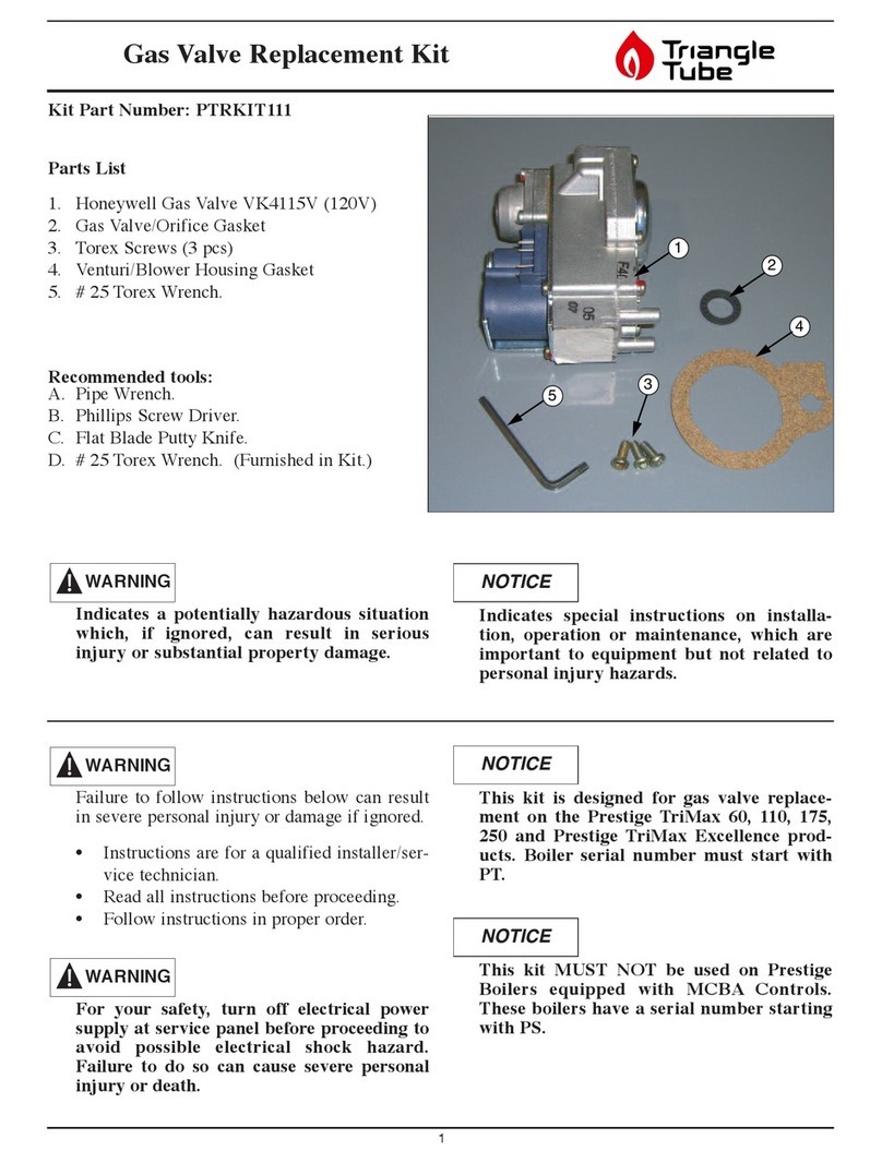
Parts List
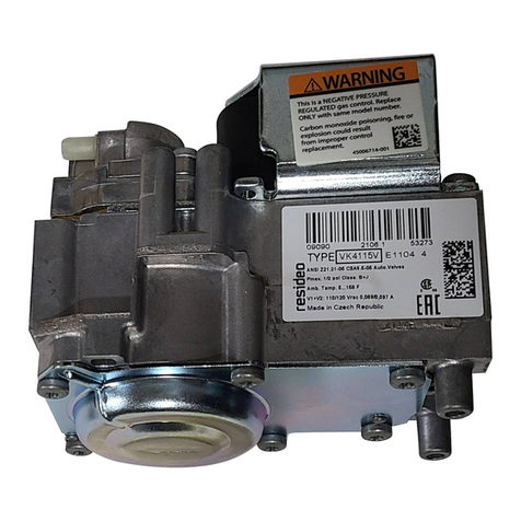
1. Honeywell Gas Valve VK8115V
2. Gas Valve/Orifice Gasket
3. Torx Screws (3 pcs)
4. Venturi/Blower Housing Gasket
5. # 25 Torx Wrench.
Recommended tools:
A. Pipe Wrench.
B. Phillips Screw Driver.
C. Flat Blade Putty Knife.
D. # 25 Torx Wrench. (Furnished in Kit.)
Failure to follow instructions below can result
in severe personal injury or damage if ignored.
•Instructions are for a qualified installer/ser-
vice technician.
• Read all instructions before proceeding.
•Follow instructions in proper order.
For your safety,turn offelectrical power
supply at service panel before proceeding to
avoid possible electrical shock hazard.
Failureto do so can cause severepersonal
injury or death.
This kit is designed for gas valve replace-
ment on the Delta Performance, Delta
Performance Plus, Modulating Delta and
Prestige 60, 110, 175, 250 and Prestige
Excellence products.
NOTICE
WARNING
WARNING
Indicates a potentially hazardous situation
which, if ignored, can result in serious
injury or substantial property damage.
Indicates special instructions on installa-
tion, operation or maintenance, which are
important to equipment but not related to
personal injuryhazards.
NOTICEWARNING
53
1
2
4
Gas Valve Replacement Kit
2
DELTA COMBUSTION HEATER
INSTRUCTIONS
1. Turn power to the unit “OFF”.
2. Shut off gas supply to the inlet of the unit at
the main manual shutoff valve.
3. Disconnect the gas supply piping to the
Combination Heater.
4. Remove air inlet elbow from the venturi.
See Fig. 1.
5. Unscrew the Phillips screw attaching the
rectifier plug to the gas valve and remove
the plug.
6. Remove and save the two Torx screws
attaching the venturi/gas valve assembly
from the blower housing. Remove the ven-
turi/ gas valve assembly from the blower
housing. Use torx wrench supplied in kit
to remove screws.
Thereis a gasket between the venturi and
blower housing. If the gasket “sticks” to the
blower housing use a flat blade putty knife to
remove any gasket material. Make sure not
to scratch or score the mating surface on the
blower housing.
7. Remove the four screws attaching the 90º
gas valve pipe fitting from the inlet of the
old valve.
8. Mount the 90º gas valve pipe fitting onto the
new gas valve. Use the 4 existing screws to
mount the fitting. Ensure the O-ring gasket
in the fitting is in place when mounting the
fitting and the mounting screws are tight
and secure.
9Remove the three screws attaching the old
gas valve to the venturi. Use torx wrench
supplied in kit to remove screws. Note ori-
entation of the venturi on the old gas valve
for reassembly of the venturi on the new gas
valve.
10. Take the new gas valve, gas valve/orifice
gasket and three Torx screws from the kit
and reassemble the gas valve to the venturi.
See Fig. 2.
Make sure the gas valve/orifice gasket is in
place before reassembling the gas valve and
venturi. Failureto do so can result in death,
serious injury or substantial property damage.
WARNING
NOTICE
2
3
3
4
1
1. Air Inlet Elbow
2. Gas Valve
3. Venturi Mounting Screws. Attaching Gas
Valve/Venturi to Blower/Housing.
4. Rectifier Plug and Philips Head Screw
Fig. 1: Delta Burner Assembly
Gas Valve Replacement Kit
For propane installations a brass orifice is
located inside the gas valve/orifice gasket.
This orifice must be placed inside of the new
gas valve/orifice gasket before reassembly.
Failure to insert the propane brass orifice,
on propane installations, before reassem-
bling the gas valve and venturi can result in
the production of carbon monoxide due to
incomplete combustion and may result in
death, serious injury or substantial proper-
ty damage.
11. With the venturi to blower housing gasket in
place reassemble the venturi/gas valve to blow-
er housing using the two mounting screws from
step 6.
For the reassembly process do not use adhe-
sive on any gasket surfaces.
12. Reconnect the rectifier plug to the gas valve
using the Phillips head screw.
13. Reattach air inlet elbow to the venturi.
14. Using pipe dope compatible with propane gas
reconnect the gas supply piping to the
Combination Heater.
15. Open the main manual gas shutoff valve. Before
placing the Combination Heater unit back into
operation check and test all gas connections for
leaks. Repair leaks if found.
Do not check for gas leaks with an open
flame. Use a bubble test. Failureto check for
gas leaks can cause severe personal injury,
death or substantial property damage.
16. Turn the electrical power ON to the
Combination Heater to return the unit back into
service.
WARNING
NOTICE
WARNING
NOTICE
3
Venturi Inlet Supply
Pressure Port
Propane
Orifice
Gas Valve/Orifice
Gasket
Gas Valve
Pipe Fitting
Gas Valve
Fig. 2: Propane Orifice and Gasket Installation
Gas Valve Replacement Kit
4
PRESTIGE BOILER INSTRUCTIONS:
1. Turn power to the unit “OFF”.
2. Shut off the gas supply to the boiler at the main
manual shutoff valve.
3. Remove the front jacket panel and swing away
the Control Module panel.
4. Remove the air inlet elbow from the venturi.
5. Unscrew the Phillips screw attaching the rectifi-
er plug to the gas valve and remove the plug.
6. Disconnect the gas supply piping inside the
PRESTIGE at the brass union located just
before the gas valve.
7. Remove and save the two Torx screws attach-
ing the venturi / gas valve assembly from the
blower housing. See Fig.3. Remove the venturi
/ gas valve assembly from the blower housing.
Use the Torx wrench supplied in the kit to
remove screws.
There is a gasket between the venturi and blow-
er housing. If gasket “sticks” to the blower
housing use a flat blade putty knife to remove
any gasket material. Make sure not to scratch or
score the mating surface on the blower housing.
8. Remove the three screws attaching the gas
valve to the venturi. Use Torx wrench sup-
plied in kit to remove screws. Note orientation
of the venturi to the old gas valve for reassem-
bly of the venturi on the new gas valve.
9. Remove the four screws attaching the “straight”
gas valve fitting from the old gas valve.
10. Remount the “straight” gas valve fitting onto
the new gas valve. Use the 4 existing screws to
mount the fitting. Ensure O-Ring gasket is in
place and all four mounting screws are tight and
secure.
11. Reassemble the new gas valve, gas valve/orifice
gasket and the three Torx screws from the kit
and reassemble the gas valve to the venturi. See
Fig. 4.
Ensure the gas valve/orifice gasket is in place
before reassembling the gas valve and venturi.
Failure to do so can result in death, serious
injury or substantial property damage.
WARNING
NOTICE
1. Gas Valve
2. Venturi
3. “Straight” Gas Valve Fitting
4. Venturi Mounting screws.
Attaching Gas Valve/Venturi to Blower
Housing
Fig. 3: Prestige Burner Assembly
Gas Valve Replacement Kit
5
For propane installations a brass orifice is locat-
ed inside the gas valve/orifice gasket. This ori-
fice must be placed inside of the new gas
valve/orifice gasket before reassembly.
Failure to insert the propane brass orifice, on
propane installations, before reassembling the
gas valve and venturi can result in the produc-
tion of carbon monoxide due to incomplete com-
bustion and may result in death, serious injury
or substantial property damage.
12. With the venturi to blower gasket in place,
reassemble the venturi / gas valve to the blower
housing using the two mounting screws from
step 7.
For the reassembly process do not use adhesive
on any gasket surface.
13. Reconnect the rectifier plug to the gas valve
using the Phillips head screw.
14. Reconnect the brass gas piping union connec-
tion. Open the main manual gas shutoff valve
before placing the PRESTIGE unit back into
operation check and test all gas connections for
leaks. Repair leaks if found.
Do not check for gas leaks with an open flame.
Use a bubble test. Failure to check for gas leaks
can cause severe personal injury, death or sub-
stantial property damage.
15. Reattach the air inlet elbow to the venturi.
16. Reposition the Control Module panel and reat-
tach the front jacket panel.
17. Turn the electrical power “ON” to the PRES-
TIGE to return the unit back into service.
WARNING
NOTICE
WARNING
NOTICE
Venturi Inlet Supply
Pressure Port
Propane
Orifice
Gas Valve/Orifice
Gasket
Gas Valve
Pipe Fitting
Gas Valve
Fig. 4: Propane Orifice Installation
Gas Valve Replacement Kit
6
COMBUSTION TEST - PRESTIGE
1. It is recommended that the installer perform a
complete combustion check to ensure the fol-
lowing combustion levels are met at high and
low inputs and the burner is operating at opti-
mum conditions.
The combustion testing and adjustments
must be performed by a qualified installer,
service agency or the gas supplier. All com-
bustion measurements must be perform with
calibrated equipment to ensure proper read-
ings and accuracy.
Failureto perform a complete combustion
test at both high and low input rates may
result in incomplete combustion and the pro-
duction of carbon monoxide, which can
cause severe personal injury, death or sub-
stantial property damage.
2. Manually place the boiler into high fire mode
by pressing the MODE button with “+” button
simultaneously on the control panel display
while in the standby (STBY) mode.
The control panel will display a H followed
by the current boiler temperature when
placed into high firetest mode.
If the combustion levels during high fire is outside
the recommended combustion settings adjust the
THROTTLE SCREW (see Fig. 5) as follows:
Counter-clockwise adjustment of the throttle
screw at high fire:
O2decreases and C02increases
Clockwise adjustment of the throttle screw at
high fire:
O2increases and CO2decreases
4. Once the combustion level is set at high fire,
manually place the boiler into low fire mode by
pressing the MODE button with “-” button
simultaneously on the control display while in
the standby (STBY) mode.
The control panel will display a L followed
by the current boiler temperature when
placed into low fire test mode.
5. If the combustion level at low fire is not within
+/- 0.2% of the combustion level measured at
high fire, remove the offset cover screw and
adjust the plastic OFFSET SCREW using a
#25 Hex key (see Fig.5) as follows:
Counter-clockwise adjustment of offset screw at
low fire:
O2increases and CO2decreases
Clockwise adjustment of offset screw at low fire:
O2decreases and CO2increases
NOTICE
NOTICE
WARNING
WARNING
Offset Pressure
Cover Screw
Throttle
Screw
Fig. 5: Combustion Adjustment - Prestige Burner
Natural Gas Propane
O2Min. 2.30% 2.70%
O2Max. 5.30% 4.70%
CO2Min. 8.80% 10.70%
CO2Max. 10.50% 12.00%
CO Max. 100 ppm 100 ppm
2008-2 Gas Valve Repl. Kit
7/30/18

Other TriangleTube Control Unit manuals
TriangleTube INSRKIT06 User manual

TriangleTube

TriangleTube INSRKIT06 User manual

TriangleTube PSRKIT74 User manual

TriangleTube

TriangleTube PSRKIT74 User manual

TriangleTube Prestige Trimax 175 User manual

TriangleTube

TriangleTube Prestige Trimax 175 User manual

TriangleTube PTRKIT112 User manual

TriangleTube

TriangleTube PTRKIT112 User manual

TriangleTube CHALLENGER CC 85 User manual

TriangleTube

TriangleTube CHALLENGER CC 85 User manual

TriangleTube PRESTIGE TriMax PTRKIT109 User manual

TriangleTube

TriangleTube PRESTIGE TriMax PTRKIT109 User manual

TriangleTube PSRKIT20 User manual

TriangleTube

TriangleTube PSRKIT20 User manual

TriangleTube PSRKIT23 User manual

TriangleTube

TriangleTube PSRKIT23 User manual

TriangleTube PGRKIT18 User manual

TriangleTube

TriangleTube PGRKIT18 User manual

TriangleTube Optima Series Installation instructions

TriangleTube

TriangleTube Optima Series Installation instructions

TriangleTube PGRKIT16 User manual

TriangleTube

TriangleTube PGRKIT16 User manual

TriangleTube PTRKIT111 User manual

TriangleTube

TriangleTube PTRKIT111 User manual

TriangleTube PRESTIGE TriMax PTRKIT205 User manual

TriangleTube

TriangleTube PRESTIGE TriMax PTRKIT205 User manual

TriangleTube Prestige Trimax 399 User manual
TriangleTube

TriangleTube Prestige Trimax 399 User manual

Popular Control Unit manuals by other brands

ITC Elio 610-00007 Replacement instructions

ITC

ITC Elio 610-00007 Replacement instructions

Xycom XVME-956 Series manual

Xycom

Xycom XVME-956 Series manual

STA-RITE WC212-143P owner's manual

STA-RITE

STA-RITE WC212-143P owner's manual

Motorola PRPMC750 Installation and use manual

Motorola

Motorola PRPMC750 Installation and use manual

Texas Instruments TCA5405EVM user guide

Texas Instruments

Texas Instruments TCA5405EVM user guide

Parker PSSNACM12A Installation & service instructions

Parker

Parker PSSNACM12A Installation & service instructions

Epson RX8130CE Applications manual

Epson

Epson RX8130CE Applications manual

TRU Components POWER CONTROL 2760 operating instructions

TRU Components

TRU Components POWER CONTROL 2760 operating instructions

Chemline SR50 Series Installation & maintenance instructions

Chemline

Chemline SR50 Series Installation & maintenance instructions

Emerson Alco Controls Thermo-TX7 Operating	 instruction

Emerson

Emerson Alco Controls Thermo-TX7 Operating instruction

ICP DAS USA iDaSer-9000 quick start

ICP DAS USA

ICP DAS USA iDaSer-9000 quick start

Nice DPRO500 Instructions and warnings for installation and use

Nice

Nice DPRO500 Instructions and warnings for installation and use

Coax SPB-N 15 operating instructions

Coax

Coax SPB-N 15 operating instructions

UTC Fire and Security Interlogix VR1910 Installation & operation instructions

UTC Fire and Security

UTC Fire and Security Interlogix VR1910 Installation & operation instructions

Toto TLE05701H Installation and owner's manual

Toto

Toto TLE05701H Installation and owner's manual

Siemens VAI60.15-15 Mounting instructions

Siemens

Siemens VAI60.15-15 Mounting instructions

EN-KO Electronics AMF 4.0 user manual

EN-KO Electronics

EN-KO Electronics AMF 4.0 user manual

rako RAK-LINK 1GPK Installing

rako

rako RAK-LINK 1GPK Installing

manuals.online logo
manuals.online logoBrands
  • About & Mission
  • Contact us
  • Privacy Policy
  • Terms and Conditions

Copyright 2025 Manuals.Online. All Rights Reserved.