Promac PBD-2870 User manual

CE-Conformity Declaration
CE-Konformitätserklärung
Déclaration de Conformité CE
Product / Produkt / Produit:
Metal lathe / Metalldrehbank / Tour à métaux
PBD-2870
Brand / Marke / Marque:
PROMAC
Manufacturer / Hersteller / Fabricant:
Tool France PROMAC, JPW Industries-Europe
9 Rue des Pyrénées ZI du Bois Chaland, 91090 LISSES / EVRY, France
We hereby declare that this product complies with the regulations
Wir erklären hiermit, dass dieses Produkt der folgenden Richtlinie entspricht
Par la présente, nous déclarons que ce produit correspond aux directives suivantes
2006/42/EC
Machinery Directive
Maschinenrichtlinie
Directive Machines
2014/30/EU
electromagnetic compatibility
elektromagnetische Verträglichkeit
compatibilité électromagnétique
designed in consideration of the standards
und entsprechend folgender zusätzlicher Normen entwickelt wurde
et été développé dans le respect des normes complémentaires suivantes
EN ISO 12100:2010
EN ISO 23125:2015
EN 60204-1:2006/AC2010
EN 61000-6-2:2005
EN 61000-6-4:2007/A1:2011
Responsible for the Documentation / Dokumentations-Verantwortung / Responsabilité de Documentation:
Head of Product-Mgmt. / Leiter Produkt-Mgmt. / Resp. Gestion des Produits
2018-10-29 Christophe SAINT SULPICE, General Manager
TOOL FRANCE SARL
TOOL FRANCE SARL, 9 Rue des Pyrénées, 91090 LISSES, France

3
EN Operating Instructions
1.0 About this Manual
This manual is provided by PROMAC, covering the safe operation and maintenance procedures for a PROMAC Model PBD-
2870 Metal Lathe. This manual contains instructions on installation, safety precautions, general operating procedures,
maintenance instructions and parts breakdown. The machine has been designed and constructed to provide consistent, long-
term operation if used in accordance with the instructions as set forth in this document.
Retain this manual for future reference. If the machine transfers ownership, the manual should accompany it.
2.0 Table of Contents
Section Page
1.0 About this manual..................................................................................................................................................... 3
2.0 Table of contents.......................................................................................................................................................3
3.0 Important safety instructions................................................................................................................................4~6
3.1 Designated use and limitations to use..............................................................................................................6
3.2 Remaining hazards............................................................................................................................................6
4.0 Specifications.........................................................................................................................................................7~8
5.0 Machine description..................................................................................................................................................9
6.0 Setup and assembly.................................................................................................................................................10
6.1 Unpacking and clean up..................................................................................................................................10
6.2 Shipping contents........................................................................................................................................... 10
6.3 Assembly......................................................................................................................................................... 10
6.4 Initial lubrication............................................................................................................................................. 10
6.5 Installation...................................................................................................................................................... 10
7.0 Electrical connections........................................................................................................................................10~11
7.1 Grounding instructions................................................................................................................................... 10
7.2 Extension cords............................................................................................................................................... 11
8.0 Adjustments...................................................................................................................................................... 11~13
8.1 Spindle speed range selection........................................................................................................................ 11
8.2 Change gear setup.......................................................................................................................................... 11
8.3 Taper turning with tailstock............................................................................................................................12
8.4 Taper turning with top slide........................................................................................................................... 12
8.5 Three jaw universal chuck.............................................................................................................................. 12
8.6 Four jaw independent chuck.......................................................................................................................... 12
8.7 Live centre.......................................................................................................................................................12
8.8 Steady and follow rest.................................................................................................................................... 13
9.0 Operating controls.................................................................................................................................................. 14
10.0 Machine operation............................................................................................................................................ 14~16
10.1 Cutting execution............................................................................................................................................14
10.2 Chucking..........................................................................................................................................................14
10.3 Cutting tool setup........................................................................................................................................... 15
10.4 Recommended spindle speeds....................................................................................................................... 15
10.5 Manual turning.......................................................................................................................................................15
10.6 Turning with auto feed...........................................................................................................................................15
10.7 Thread cutting........................................................................................................................................................16
10.8 Drilling operation....................................................................................................................................................16
11.0 User maintenance............................................................................................................................................. 17~18
11.1 Lubrication.......................................................................................................................................................17
11.2 Readjustments...........................................................................................................................................17~18
12.0 Troubleshooting...................................................................................................................................................... 19
13.0 Environmental protection....................................................................................................................................... 19
14.0 Available accessories............................................................................................................................................... 19
15.0 Replacement parts............................................................................................................................................ 20~39
16.0 Wiring diagrams................................................................................................................................................ 40~41

3.0 IMPORTANT SAFETY
INSTRUCTIONS
READ ALL INSTRUCTIONS BEFORE USING THIS DRILL PRESS.
– To reduce risk of injury:
1. Read and understand entire owner’s manual before
attempting assembly or operation of this drill press.
2. Read and understand the warnings posted on the
machine and in this manual.
3. Replace warning labels if they become obscured or
removed.
4. This machine is designed and intended for use by properly
trained and experienced personnel only. If you are not
familiar with the proper and safe operation of a drill press,
do not use until proper training and knowledge have been
obtained.
5. Do not use this machine for other than its intended use. If
used for other purposes, JET disclaims any real or implied
warranty and holds itself harmless from any injury that
may result from that use.
6. Always wear approved safety glasses or face shield while
using this machine. (Everyday eyeglasses only have impact
resistant lenses; they are not safety glasses.)
7. Before operating this machine, remove tie, rings, watches
and other jewellery, and roll sleeves up past the elbows.
Remove loose clothing and confine long hair. Non-slip
footwear or anti-skid floor strips are recommended. Do
not wear gloves.
8. Wear hearing protection (plugs or muffs) during extended
periods of operation.
9. Some dust created by sawing may contain chemicals
known to cause cancer, birth defects or other
reproductive harm. Some examples of these chemicals
are:
Lead from lead based paint.
Crystalline silica from bricks, cement and other
masonry products.
Arsenic and chromium from chemically treated
lumber.
Your risk of exposure varies, depending on how often you
do this type of work. To reduce your exposure to these
chemicals, work in a well-ventilated area and work with
approved safety equipment, such as face or dust masks
that are specifically designed to filter out microscopic
particles.
10. Do not operate this machine while tired or under the
influence of drugs, alcohol or any medication.
11. Make certain the switch is in the OFF position before
connecting the machine to the power supply. Turn off all
controls before unplugging.
12. Make certain the machine is properly grounded. Connect
to a properly grounded outlet only. See Grounding
instructions.
13. Make all machine adjustments or maintenance with the
machine unplugged from the power source.
14. Remove adjusting keys and wrenches. Form a habit of
checking to see that keys and adjusting wrenches are
removed from the machine before turning it on.
15. Keep safety guards in place at all times when the machine
is in use. If removed for maintenance purposes, use
extreme caution and replace the guards immediately after
maintenance is complete.
16. Check damaged parts. Before further use of the machine,
a guard or other part that is damaged should be carefully
checked to determine that it will operate properly and
perform its intended function. Check for alignment of
moving parts, binding of moving parts, breakage of parts,
mounting and any other conditions that may affect its
operation. A guard or other part that is damaged should
be properly repaired or replaced.
17. Provide for adequate space surrounding work area and
non-glare, overhead lighting.
18. Keep the floor around the machine clean and free of scrap
material, oil and grease.
19. Keep visitors a safe distance from the work area. Keep
children away.
20. Make your workshop child proof with padlocks, master
switches or by removing starter keys.
21. Give your work undivided attention. Looking around,
carrying on a conversation and “horse-play” are careless
acts that can result in serious injury.
22. Keep an ergonomic body position. Maintain a balanced
stance at all times so that you do not fall or lean against
the chuck or other moving parts. Do not overreach or use
excessive force to perform any machine operation.
23. Use the right tool at the correct speed and feed rate. Do
not force a tool or attachment to do a job for which it was
not designed. The right tool will do the job better and
safer.
24. The machine is intended for indoor use. To reduce the risk
of electric shock, do not use outdoors or on wet surfaces.
25. Do not handle plug or machine with wet hands.
26. Use recommended accessories; improper accessories may
be hazardous.
27. Maintain tools with care. Keep tools sharp and clean for
the best and safest performance. Follow instructions for
lubricating and changing accessories.
28. Turn off machine and disconnect from power before
cleaning. Use a brush or compressed air to remove chips
or debris; do not use bare hands.
29. Do not stand on the machine. Serious injury could occur if
the machine tips over.
30. Never leave the machine running unattended. Turn the
power off and do not leave the machine until it comes to
a complete stop.

5
31. Remove loose items and unnecessary work pieces from
the area before starting the machine.
32. Pull the mains plug if the machine is not in use.
33. Make sure the workpiece is securely clamped.
Familiarize yourself with the following safety notices used in this manual:
WARNING: This means that if precautions are not heeded, it may result in serious, or possibly even fatal, injury.
CAUTION: This means that if precautions are not heeded, it may result in minor injury and/or possible machine
damage.
SAVE THESE INSTRUCTIONS
WARNING:
These symbols blow advise that you follow the correct safety procedures when using this machine.
Read and understand the entire user
manual before attempting assembly or
machine operation.
Always wear approved working outfit
Wear safety goggles.
Wear ear protection.
Always wear the approved working outfit
Wear safety shoes.
Remove tie, rings, watches, jewellery.
Roll up sleeves above elbows.
Remove all loose clothing and confine
long hair
Make all machine adjustments or
maintenance with the machine unplugged
from the power source.
Any work piece stock extending the rear
end of the headstock must be covered
on its entire length. High danger of injury
Do not operate this machine under the
influence of drugs, alcohol or medication
Do not wear gloves while operating this
machine
Connection and repair work on the
electrical installation may be carried out by
a qualified electrician only.
Never reach into the machine while it is
operating or running down.

6
3.1 Designated use and limitations to use
The machine is designed for turning and drilling machinable metal and plastic materials only.
The workpiece must allow to safely be loaded, supported and clamped.
The machine is intended for indoor use. The protection rating of the electrical installation is IP 54.
To avoid tipping, the machine must be bolted down with four anchor bolts.
If used for other purposes, JET disclaims any real or implied warranty and holds itself harmless from any injury that may result from
that use.
WARNING:
The machine is not suitable for machining magnesium…high danger to fire !
Never place your fingers in a position where they could contact any rotating parts or chips.
Check the save clamping of the work piece before starting the machine.
Don’t exceed the clamping range of the chuck.
Work pieces longer than 3 times the chucking diameter need to be supported by the tailstock or a steady rest.
Avoid small chucking diameters at big turning diameters. Avoid short chucking lengths and small chucking contact.
Do not exceed the max speed of the work holding device.
Use the right tool at the correct speed and feed rate. Do not force a tool or attachment to do a job for which it was not designed. The
right tool will do the job better and more safely.
Use recommended accessories; improper accessories may be hazardous.
Maintain tools with care. Keep cutting tools sharp and clean for the best and safest performance.
Follow instructions for lubricating and changing accessories.
Do not attempt to adjust or remove tools during operation.
Never stop a rotating chuck or workpiece with your hands.
Choose a small spindle speed when working unbalanced work pieces and for threading and tapping operations.
Any work piece stock extending the rear end of the headstock must be covered on its entire length. High danger of injury!
Long work pieces may need a steady rest support. A long and thin work piece can suddenly bend at high speed rotation.
Never move the tailstock or tailstock quill while the machine is running.
Remove cutting chips with the aid of an appropriate chip hook when the machine is at a standstill only.
Measurements and adjustments may be carried out when the machine is at a standstill only.
Maintenance and repair work may only be carried out after the machine is protected against accidental starting, pull the mains plug.
Remove loose items and unnecessary work pieces from the area before starting the machine.
Rotate workpiece by hand before applying power. Use lowest speed when starting new workpiece.
Tighten all locks before operating.
3.2 Remaining hazards
When using the machine according to regulations some remaining hazards may still exist.
The rotating work piece and chuck can cause injury.
Thrown and hot work pieces and cutting chips can lead to injury.
Chips and noise can be health hazards. Be sure to wear personal protection gear such as safety goggles and ear protection.
The use of incorrect mains supply or a damaged power cord can lead to injuries caused by electricity.
When opening the electrical cabinet, the grid-feeding voltage persists. Therefore pay attention every time you enter it.

7
4.0 Specifications
Model number.................................................................................................................................................................................PBD-2870
Stock number…………………………………………………………………….......................................................................................................... PBD-2870
Motor and electricals:
Motor type…………………………………………………….................................................................................................................Induction motor
Motor power....................................................................................................................................................................................1.1 kW
Power supply..................................................................................................................................................................1~230V, PE, 50 Hz
Protection class................................................................................................................................................................................... IP 54
Listed load amps................................................................................................................................................................................. 6.4 A
Machine lamp......................................................................................................................................................Halogen lamp 24V, 35 W
Coolant pump..................................................................................................................................................................................... 40 W
Capacities:
Centre height................................................................................................................................................................................. 140 mm
Swing over bed...............................................................................................................................................................................280 mm
Swing over cross slide.................................................................................................................................................................... 170 mm
Distance between Centres.............................................................................................................................................................700 mm
Spindle:
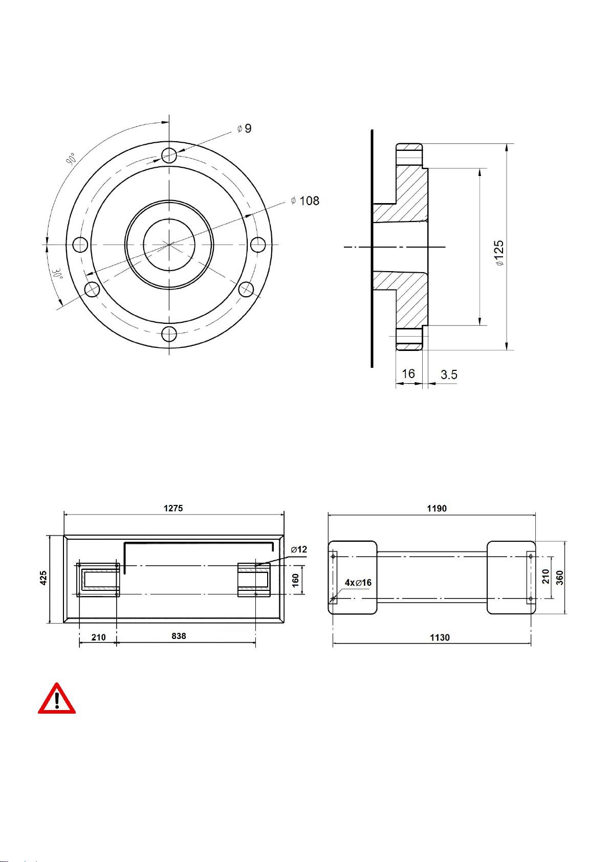
Spindle nose mounting.................................................................................cylindrical mount (Ø125mm, Ø96mm, Ø108-3xØ9 & 4xØ9)
Spindle bore..................................................................................................................................................................................... 26 mm
Spindle taper........................................................................................................................................................................................MT4
Number of spindle speeds........................................................................................................................................................................ 6
Range of spindle speeds................................................................................................................................................... 150 ~ 2000 /min
Tailstock:
Tailstock ram travel..........................................................................................................................................................................85 mm
Tailstock taper......................................................................................................................................................................................MT2
Bed and Slides:
Bed width.......................................................................................................................................................................................180 mm
Cross slide travel............................................................................................................................................................................ 160 mm
Top slide travel.................................................................................................................................................................................60 mm
Tool size max..............................................................................................................................................................................12x12 mm
Lead screw pitch................................................................................................................................................................................ 3 mm
Longitudinal feeds.........................................................................................................(6x) 0.07 / 0.1 / 0.14 / 0.2 / 0.28 / 0.40 mm/rev
Metric threads........................................................................................................................................................(21x) 0.2~4.0 mm/rev
Inch threads........................................................................................................................................................................(21x) 8 ~ 56 TPI
Materials:
Machine Bed............................................................................................................ Cast iron, induction hardened and precision ground
Headstock, tailstock, slides........................................................................................................................................................... Cast iron
Spindle bearings..............................................................................................................................Taper roller bearings, quality level P5
Sound emission in idle 1........................................................................................................................................................ 73.4 dB (LpA)
Sound emission during cutting 1............................................................................................................................................78.3 dB (LpA)
1Sound emission measured according to EN ISO 11202, in 1m distance, 1.6m above ground. The specified values are emission levels
and are not necessarily to be seen as safe operating levels. As workplace conditions vary, this information is intended to allow the user
to make a better estimation of the hazards and risks involved only.
Dimensions and Weights:
Overall dimensions, assembled (W x D x H)..................................................................................................1380 x 700 x 650 (1285) mm
Shipping dimensions (W x D x H) (Separate packing).......................................................... 1320 x 700 x 690mm & 820 x 680 x 430 mm
Shipping dimensions (W x D x H) (Whole packing)................................................................................................. 1400 x 700 x 1470mm
Net weight (approximate)................................................................................................................................................................. 280kg
Shipping weight (approximate)........................................................................................................................................................ 320 kg
L = length; W = width; H= height; D= depth
The specifications in this manual were current at time of publication, but because of our policy of continuous improvement, JET reserves
the right to change specifications at any time and without prior notice, without incurring obligations.

8
4.1 Spindle nose mounting:
Figure 4-1: Spindle nose mounting
4.2 Anchor bolt hole pattern:
Figure 4-2: Lathe Bed (left) & Stand (right) anchor bolt pattern
WARNING:
To avoid tipping, the machine must be bolted down with four anchor bolts (not provided).
Φ96

9
5.0 Machine Description
Figure 5-1: Machine description
A............................................ Machine cabinet stand
B...................................................................Gear box
C..............................................................Pulley cover
D................................................................Headstock
E............................................ Chuck and chuck guard
F.................................. Tool post and tool post guard
G..........................................................Machine lamp
H......................................................... Coolant nozzle
I....................................................................Top slide
J.....................................................................Carriage
K................................................................... Tailstock
L............................................................. Splash guard
M................................................................Lathe bed
N...............................................................Lead screw
O.................................................................. Chip tray
P....................................................................... Apron
Q.................................................... Anchor bolt holes
Figure 5-2: Machine description
R............................................Feed speed select knob
S........................................ Feed forward/off/reverse
T....................................................... Coolant ON/OFF
U............................................Spindle power ON/OFF
V..........................................Spindle forward/reverse
X....................................................... Emergency Stop
Y....................................................Apron hand wheel
Z.............................................Cross slide hand wheel
AA .........................................................Half nut lever
BB .............................................Top slide hand wheel
CC ........................................................ Threading dial
Figure 5-3 Machine description
VV ......................................................... Top slide lock
XX .......................................................Cross slide lock
YY .................................... Top slide taper adjustment
ZZ ...........................................................Carriage lock

10
6.0 Setup and Assembly
WARNING:
Read and understand the entire contents of this manual
before attempting assembly or operation. Failure to comply
may cause serious injury.
6.1 Unpacking and clean up
Remove all contents from shipping crate and compare parts to
the contents list in this manual. If shipping damage or any part
shortages are identified, contact your distributor. Do not
discard crate or packing material until drill press is assembled
and running satisfactorily.
Clean all rust protected surfaces with kerosene or a light
solvent. Do not use lacquer thinner, paint thinner or gasoline,
as these can damage plastic components and painted surfaces.
6.2 Shipping contents
1
1
1
1
1
1
1
1
1
1
1
1
1
1
1
1
1
1
1
1
1
1
Machine
Cabinet stand (Optional, PBD2870-807)
Coolant facility (Optional, 59500112)
Machine lamp
125mm 3-jaw universal chuck (PBD2870-452)
125mm 4-jaw chuck (Optional, PBD2870-457)
265mm face plate (Optional, PBD2870-458)
Chuck guard
4-way tool post
Tool post guard
Set of change gears
Threading dial
MT4 fixed centre (PBD2870-267)
MT2 fixed centre (PBD2870-265)
MT2 live centre (PBD2870-266)
Steady rest (PBD2870-714)
Follow rest (Optional, PBD2870-715)
Operating tools in tool box
Lead screw guard
Thread dial
Oil can
Operating instructions and parts manual
(see end of document for detailed content)
6.3 Assembly
The machine comes completely assembled.
Install the drive belt (V-belt).
Inspect that all fasteners are tight.
6.4 Initial lubrication
The machine must be serviced at all lubrication points before it is
placed into service (see chapter 11.1 for lubrication).
6.5 Installation
Unbolt the lathe from the shipping crate bottom.
Use heavy duty fibre belt for lifting the machine off the pallet.
Warning:
The machine is heavy (320 kg)!
Assure the sufficient load capacity and proper condition of your
lifting devices.
Never step underneath suspended loads.
To avoid tipping, the machine must be bolted down with four
anchor bolts (not provided).
To avoid twisting the bed, make sure the setup surface is
absolutely flat and level.
Loosen anchor bolts, shim and tighten bolts if needed.
The machine must be level to be accurate!
7.0 Electrical Connections
WARNING:
All electrical connections must be done by a qualified
electrician in compliance with all local codes and ordinances.
Failure to comply may result in serious injury.
The PBD-2870 Metal Lathes are rated at 1~230V, PE, 50Hz
power supply. The machines come with a plug designed for
use on a circuit with a grounded outlet.
Mains connection and any extension cords and plugs used
must comply with the information on the machine license
plate.
The mains connection must have a 16A surge-proof fuse.
Only use extension cords marked H07RN-F, with wires 1,5mm2
or more.
The total length of cord may not exceed 18 Meter
Power cords and plugs must be free from defects.
Connections and repairs to the electrical equipment may only
be carried out by qualified electricians.
The machine is equipped with 2.3m power cord and plug.
Before connecting to power source, be sure main switch is in
off position.
7.1 Grounding instructions
This tool must be grounded. In the event of a malfunction or
breakdown, grounding provides a path of least resistance for
electric current to reduce the risk of electric shock. This tool is
equipped with an electric cord having an equipment-
grounding conductor and a grounding plug. The plug must be
inserted into an appropriate outlet that is properly installed
and grounded in accordance with all local codes and
ordinances.
WARNING:
Improper connection of the equipment-grounding conductor
can result in a risk of electric shock. Check with a qualified

11
electrician or service person if you are in doubt as to whether
the outlet is properly grounded. Do not modify the plug
provided with the tool.
The green/yellow conductor is the equipment-grounding
conductor. If repair or replacement of the electric cord or plug
is necessary, do not connect the equipment-grounding
conductor to a live terminal.
Use only 3-wire extension cords with grounding plugs.
Repair or replace damaged or worn cord immediately.
7.2 Extension cords
The use of extension cords is discouraged; try to position
machines near the power source. If an extension cord is
necessary, make sure it is in good condition.
An undersized cord will cause a drop in line voltage resulting in
loss of power and overheating.
Only use extension cords marked H07RN-F, with wires 1,5mm2
or more.
The total length of cord may not exceed 18 Meter
Extension cords and plugs must be free from defects.
8.0 Adjustments
8.1 Changing spindle speed
The speeds of the lathe are controlled by the position of the
belt on the pulleys (Fig 8-1).
Figure 8-1: Spindle speed chart
Remove the pulley cover (C, Fig 5-1) to change the belt
position. Reinstall the pulley cover.
8.2 Change gear setup
Remove the pulley cover.
The rotational speed of the lead screw, and hence the rate of
feed of the cutting tool, is determined by the gear
configuration and by the feed speed select lever (R, Fig 5-2).
Assemble the gears with desired setup (Fig 8-2)
Figure 8-2: Change gear setup
Adjust gears to mesh with upper and lower gear.
Placing ordinary paper in between gears helps to adjust for
correct gear spacing (… remove the paper afterwards!).
Reinstall the pulley cover.

12
8.3 Taper turning with tailstock
Mount the work piece fitted with the drive dog between
centres. The drive dog is driven by the face plate.
Lubricate the tailstock centre with grease to prevent tip from
overheating.
Figure 8-3: Taper turning between centres
To turn a taper, offset the tailstock, loosen the locking screws
(Z, Fig 8-3) and use screws (Y) to adjust.
After taper turning, the tailstock must be returned to its
original position. Turn a test piece and adjust until the machine
turns a perfect cylinder.
8.4 Taper turning with top slide
By angling the top slide, tapers may be turned.
Loosen two hex nuts (A, Fig 8-4) and rotate the top slide
according to the graduated scale (B).
Figure 8-4: Taper turning with top slide
8.5 Three jaw universal chuck
With this universal chuck, cylindrical, triangular and hexagonal
stock may be clamped (Fig 8-5).
Figure 8-5: Three jaw universal chuck
To hold big diameter stock, a set of OD chuck jaws is supplied.
The jaws need to be inserted to the chuck in the correct order.
Use Molykote Paste G (or adequate grease) to lubricate the
jaws.
8.6 Four jaw independent chuck (Optional)
This chuck has four independently adjustable chuck jaws (Fig
8-6).
These permit the holding of square and asymmetrical pieces
and enables accurate concentric set-up of cylindrical pieces.
Figure 8-6: Four jaw independent chuck
8.7 Live centre
The live centre (Fig 8-7) is mounted in ball bearings.
Its use is highly recommended for speeds above 500 RPM.

13
Figure 8-7: Live centre
To eject the live centre, fully retract the tailstock quill.
8.8 Steady rest ,and follow rest (Optional)
The rests prevent flexing of long and thin work pieces under
pressure from the tool.
The steady rest (Fig 8-8) serves as a support for longer shafts
and ensures a safe and chatter free operation.
Figure 8-8: Steady rest
The follow rest (Fig 8-9) is mounted on the carriage and
follows the movement of the tool.
Figure 8-9: Follow rest
Note:
Set the fingers (2) snug but not overly tight.
Lubricate the fingers to prevent premature wear.

14
9.0 Operating Controls
Refer to Figure 9-1:
R............................................. Feed select knob
S................................Feed forward/off/reverse
T.............................................. Coolant ON/OFF
U................................... Spindle power ON/OFF
V................................. Spindle forward/reverse
X.............................................. Emergency Stop
Figure 9-1: Operating Controls
10.0 Machine Operation
10.1 Cutting execution
Before starting the machine check the proper chucking.
Close the chuck guard and pulley cover before you start the
machine.
Select running direction, forward or reverse (V, Fig 9-1).
You can start the machine with the green ON-button (U).
The red OFF-button stops the machine.
The emergency stop button (X) stops all machine functions.
Turn emergency stop button clockwise to reset.
The work lamp (G, Fig 5-1) operates independently; ON/OFF
switch is on top of lamp housing.
Unplug the machine if not in use.
10.2 Chucking
Do not exceed the max speed of the work holding device.
Jaw teeth and scroll must always be fully engaged. Otherwise
chuck jaws may break and fly off in rotation (Fig 10-1).
Figure 10-1: Poor jaw engagements
Avoid long workpiece extensions. Parts may bend (Fig 10-2)
or fly off (Fig 10-3). Use tailstock or rest to support.
Figure 10-2: Workpiece too long
Figure 10-3: Workpiece too long
Avoid short clamping contact (A, Fig 10-4) or clamping on a
minor diameter (B). Face locate workpiece for added support
Figure 10-4: Poor clamping

15
10.3 Cutting Tool Setup
The cutting angle is correct when the cutting edge is in line
with the centre axis of the work piece. Use the point of the
tailstock centre as a gauge and shims under the tool to obtain
the correct centre height (Fig 10-5).
Figure 10-5: Cutting tool setup
Use a minimum of two screws to clamp the cutting tool.
Avoid large tool extensions.
10.4 Recommended spindle speeds
ATTENTION:
Generally speaking, the smaller the cut diameter, the greater the
RPM required. Soft materials require higher speeds; hard metals
slower speeds.
Metal is usually machined with coolant or cutting oil applied.
Recommended spindle speeds for cutting 10mm diameter,
with HSS tools (High speed steel tools):
Plastic: ................................................................. 2000 /min
Aluminium:.......................................................... 2000 /min
Brass: ...................................................................1000 /min
Cast iron:............................................................. 1000 /min
Mild steel:.............................................................. 800 /min
High carbon steel:................................................. 600 /min
Stainless steel:....................................................... 300 /min
For carbide tools (HM), 5 times higher speeds can be chosen.
For example:
Turning mild steel at a diameter of 20mm allows
With HSS tool......................................................... 400 /min
With carbide tool................................................. 2000 /min
10.5 Manual turning
Apron travel (Y, Fig 10-6), cross travel (Z) and top slide travel
(BB) can be operated for longitudinal and cross feeding.
Figure 10-6: Machine controls
The correct feed depends on the material to be cut, the cutting
operation, the type of tool, the rigidity of the work piece
chucking, the depth of cut and the desired surface quality.
10.6 Turning with auto feed
Move the half-nut lever (AA, Fig 10-6) down, to engage the
automatic longitudinal feed. Move it up to disengage
Three feed rates are readily available by rotating the feed
select knob (R, Fig 9-1).
Figure 10-7: Available feed rates
For example:
Operation feed/rev feed select knob
Stock removal 0,28mm.............................. III
Finishing cut 0.14mm............................... II
Micro finishing cut 0.07mm................................ I
NOTE: Three additional feed rates are available with different
change gear setup (Fig 10-7).

16
10.7 Thread cutting
Threading is performed in multiple passes with a threading
tool.
Each depth of cut should be about 0,2mm and become less for
the finishing passes.
A) Cut inch and metric threads:
Set the machine up for the desired threading pitch (see
chapter 8.2).
Select the lowest possible spindle speed.
Engage the halve nut (AA, Fig 10-6).
NOTE: The halve nut must stay engaged during the entire
threading process.
- Set the tool up for the threading pass.
- Start the motor.
- When the tool approaches the end of cut, stop the motor and
at the same time back the tool out, so that it clears the thread
diameter.
- Start the motor in reverse direction, let the cutting tool travel
back to the starting point.
Repeat these steps until you have obtained the desired results.
B) Cut metric threads with threading dial
On most metric threads the threading dial (CC, Fig 10-8) can be
used.
The halve nut can be opened at the end of cut, rather than the
motor being stopped and reversed.
Figure 10-8: Threading Dial
Select threading dial gear 28T or 30T
The halve nut may only be engaged at the corresponding
graduation match on the threading dial (Fig 10-9).
Figure 10-9: Threading dial setup
Note:
For thread pitches of 0,2/0,3/0,5/0,6/0,75/ 1,0/ 1,5/3 mm the
half nut can be engaged at any point.
(lead screw pitch = 3 mm = can be divided by thread pitch).
10.8 Drilling operation
Use a drill chuck with MT2 arbor (option) to clamp centre drills
and twisted drills in the tailstock (Fig 10-10)
Figure 10-10: Drilling operation
For recommended speeds refer to section 10.4
To eject the drill chuck, fully retract the tailstock quill.

17
11.0 User-Maintenance
WARNING:
Before any intervention on the machine, disconnect it from
electrical supply, pull the mains plug. Failure to comply may
cause serious injury.
An important security factor is the cleaning of the machine, of
bed, carriage and slides, of the floor and the surrounding
places.
Loose objects could come into contact with the moving chuck
or workpiece, creating hazards.
Empty the chip tray regularly.
Replace the coolant regularly, follow manufacturer’s advice.
Check that bolts are tight and electrical cords are in good
condition. If an electrical cord is worn, cut, or damaged in any
way, have it replaced immediately.
11.1 Lubrication
Spindle bearings are pre-lubricated and sealed, and require no
further lubrication.
A) Weekly apply oil:
DIN 51502 CG ISO VG 68
(e.g. BP Maccurat 68, Castrol Magna BD 68, Mobil Vectra 2)
1…oil balls on change gear hubs
2…oil bed ways lightly
3…oil tailstock quill over entire length
4…oil lead screw on entire length
5…oil ball on lead screw bracket
6…oil balls on top slide
7…oil balls on tailstock
8...oil balls on carriage
9...oil balls on apron
B) Monthly apply grease:
DIN 51807-1 non slinging grease
(e.g. BP L2, Mobilgrease Special).
10…grease teeth of change gears
11…grease rack over entire length
Gear box oil:
DIN 51517-2 CL ISO VG 68
(e.g. BP Energol HLP 68, Mobil DTE Oil Heavy Medium)
Oil must be up to indicator mark in oil sight glass (L, Fig 11-1).
In case of need, fill oil by removing plug (M).
Figure 11-1: Gearbox oil fill-up
Change the oil in the gearbox every 1000 operating hours.
Drain oil by removing drain plug (K).
11.2 Readjustments
A) Bearing adjustment:
The main spindle taper roller bearings are adjusted at the
factory.
If end play becomes evident after considerable use the
bearings may be adjusted.
Loosen two hex socket cap screws (A, Fig 11-2). Tighten nut (B)
until end play is taken up.
Figure 11-2: Bearing adjustment
Tighten nut carefully, the spindle should still revolve freely.
Excessive preloading will damage the bearings.
Tighten the screws.

18
B) Cross slide and Top slide adjustment:
Each slide is fitted with a gib (C, Fig 11-3) and can be adjusted
with screws (E) fitted with lock nuts (D).
Figure 11-3: Slide adjustment
Adjust until slides move freely without play.
C) Cross slide spindle adjustment
Remove the top slide and adjust the grub screw (F, Fig 11-4) until
the backlash between the spindle and the nut is eliminated.
Figure 11-4: Cross slide spindle adjustment

19
12.0 Troubleshooting
Symptom
Possible Cause
Correction *
Lathe will not start.
Lathe unplugged from wall, or motor.
Check all plug connections.
Fuse blown, or circuit breaker tripped.
Replace fuse, or reset circuit breaker.
Cord damaged.
Replace cord.
Chuck guard not closed.
Close chuck guard.
Pulley cover removed
Install pulley cover
Lathe does not come up
to speed.
Extension cord too light or too long.
Replace with adequate size and length cord.
Low current.
Contact a qualified electrician.
Lathe vibrates
excessively.
Base on uneven surface.
Locate lathe on even floor.
Lathe not bolted to the floor
Bolt machine to the floor
Unbalanced workpiece
Reduce speed
Workpiece deflection
Improve chucking length or diameter, support on
tailstock end
Tool deflection
Reduce tool length
Slide backlash
Adjust slides
Slides running dry
Lubricate with oil
Dull tool tip
Re-sharpen or change tool
Chip load too high
Reduce depth of cut or feed
Noisy operation
Dry change gear hubs.
Lubricate with oil.
Dry change gears
Lubricate with grease.
Tool tip burns
Cutting speed too high
Reduce spindle speed
Dull tool tip.
Re-sharpen or change tool
Dry cutting.
Use coolant.
Feeding too slowly.
Increase feed rate.
Machine turns a taper.
Tailstock alignment is offset.
Align tailstock position.
Machine bed is twisted.
Stand supporting surface must be flat. Shim if
needed
Workpiece deflection.
Reduce depth of cut or feed
Drill chuck or arbor
does not stay in place.
Dirt, grease, etc. on arbor, chuck, or
tailstock quill
Clean all mating surfaces thoroughly with a
cleaner-degreaser.
*WARNING: Some corrections may require a qualified electrician.
Table 1
13.0 Environmental Protection
Protect the environment.
Dispose all packaging material in an environmental friendly manner.
Dispose coolant in an environmentally friendly manner.
Your appliance contains valuable materials which can be recovered or recycled. Please leave it at a specialized institution.
14.0 Available Accessories
Refer to the PROMAC price list.

20
15.0 Replacement Parts
PBD-2870 Assembly Breakdown -1
Other manuals for PBD-2870
1
Table of contents
Languages:
Other Promac Lathe manuals

Promac
Promac PBD-3069 User manual

Promac
Promac PBD-1830V User manual

Promac
Promac GH-1640ZX User manual

Promac
Promac 941VA User manual

Promac
Promac PBD-2870 User manual

Promac
Promac PBD-2140V User manual

Promac
Promac BD-7 User manual

Promac
Promac 941A User manual

Promac
Promac PBD-2555V User manual

Promac
Promac PBD-2555V User manual
Popular Lathe manuals by other brands

Clarke
Clarke MetalWorker CL300M Operating & maintenance instructions

Atrump
Atrump KL Series Operator's manual & parts list

Axminster
Axminster WL-46A instruction manual

Laguna Tools
Laguna Tools REVO 24-36 Original instructions

Jet
Jet ZH Series Operation and maintenance instructions

Woodstock
Woodstock SHOP FOX W1752 s Specifications