Operation
Introduction
Groomingisperformedintheturfcanopyabovethe
soillevel.Groomingpromotesverticalgrowthofgrass
plants,reducesgrain,andseversstolons,producing
adenserturf.Groomingproducesamoreuniform
andtighterplayingsurfaceforfasterandtrueraction
ofthegolfball.
Groomingshouldnotbeconsideredasareplacement
forverticutting.Verticuttingisgenerallyamore
rigorousandperiodictreatmentthatcantemporarily
damagetheplayingsurface,whilegroomingisa
routineandgentlertreatmentdesignedtomanicure
theturf.
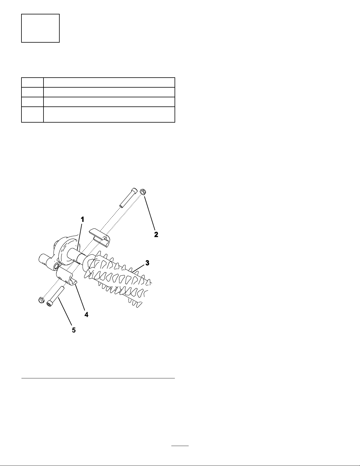
g006671
Figure18
1.Grassrunners(stolons)2.Thatch
Groomingbrushesarelessintrusivethanconventional
groomingbladeswhenadjustedtolightlycontactthe
turfcanopy.Brushingmaybebetterfortheultra-dwarf
cultivars,sincethesegrasstypeshaveanupright
growthpatternanddonotllinwellthroughhorizontal
growth.Brushescaninjureleaftissueiftheyareset
topenetratetoodeeplyintothecanopy.
Groomerbladesshouldneverpenetratethesoil.They
areeffectiveincuttingrunnersandremovingthatch.
Becausegroominginjuresleaftissue,avoidgrooming
duringperiodsofhighstress.Coolseasonspecies,
suchascreepingbentgrassandannualbluegrass,
shouldnotbegroomedduringhigh-temperature(and
high-humidity)periodsinmidsummer.
Manyvariablesaffecttheperformanceofgrooming,
including:
•Thetimeoftheyear(i.e.,thegrowingseason)and
theweatherpattern
•Thegeneralconditionofeachgreen
•Thefrequencyofgrooming/cutting—bothhow
manycuttingsperweekandhowmanypasses
percutting
•Theheight-of-cutsettingonthemainreel
•Theheight/depthsettingonthegroomingreel
•Howlongthegroomingreelhasbeeninuseon
thegreen
•Thetypeofgrassonthegreen
•Theoverallgreensmanagementprogram(i.e.,
irrigation,fertilizing,spraying,coring,overseeding,
etc.)
•Trafc
•Stressperiods(i.e.,hightemperatures,high
humidity,unusuallyhightrafc)
Thesefactorscanvaryfromgreentogreen.Inspect
thegreensfrequentlyandchangethegrooming
practiceasneeded.
Variousgroomingshaftassembliesareavailable.The
13mm(1/2inch)spacingallowsyoutogroomslightly
deepertocutstolonswithoutthinningouttheturf
excessively.Byremovingspacersandaddingblades
orbyaddingspacersandremovingblades,youcan
adjustthespacingbetweenthegroomerandbladeto
6mm(1/4inch)or19mm(3/4inch).
Note:Groomwitha6mm(1/4inch)bladespacing
forfast-growthperiods(springthroughearlysummer)
tothinoutthetoplayerofthecanopy.Groomwith
a19mm(3/4inch)bladespacingforslowergrowth
periods(latesummerthroughfallandwinter).During
high-stressperiods,usingthegroomingreelmay
causedamagetotheturf.
Note:Usingthegroomerreelimproperlyortoo
aggressively(i.e.,toodeeportoofrequentgrooming)
mayunnecessarilystresstheturf,causingsevereturf
damage.Usethegroomercautiously.
Note:Continuechangingthedirectionofcut
wheneveryouusethegroomer.Thisenhancesthe
effectsofthegrooming.
Note:Operatethegroomerinastraightlineasmuch
aspossible.Usecautionwhenturningwhileoperating
thegroomer.
10