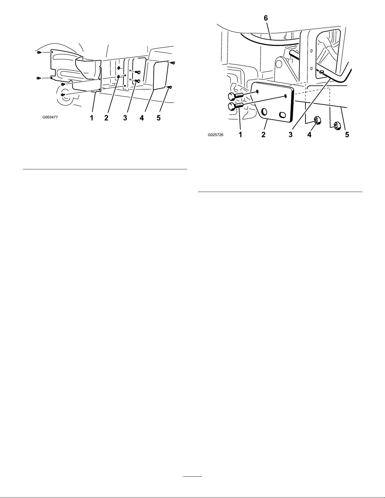
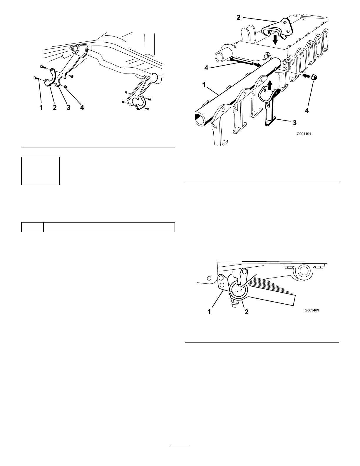
2.Looselyinstallthepivottubebracketontothe
rightside(Figure5).
3.Slidetheright-handsideofthepivottubeinto
therightsidepivottubebracket(Figure5).
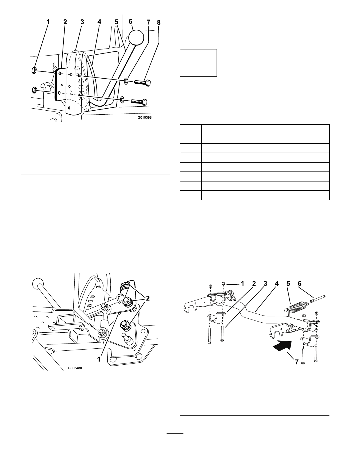
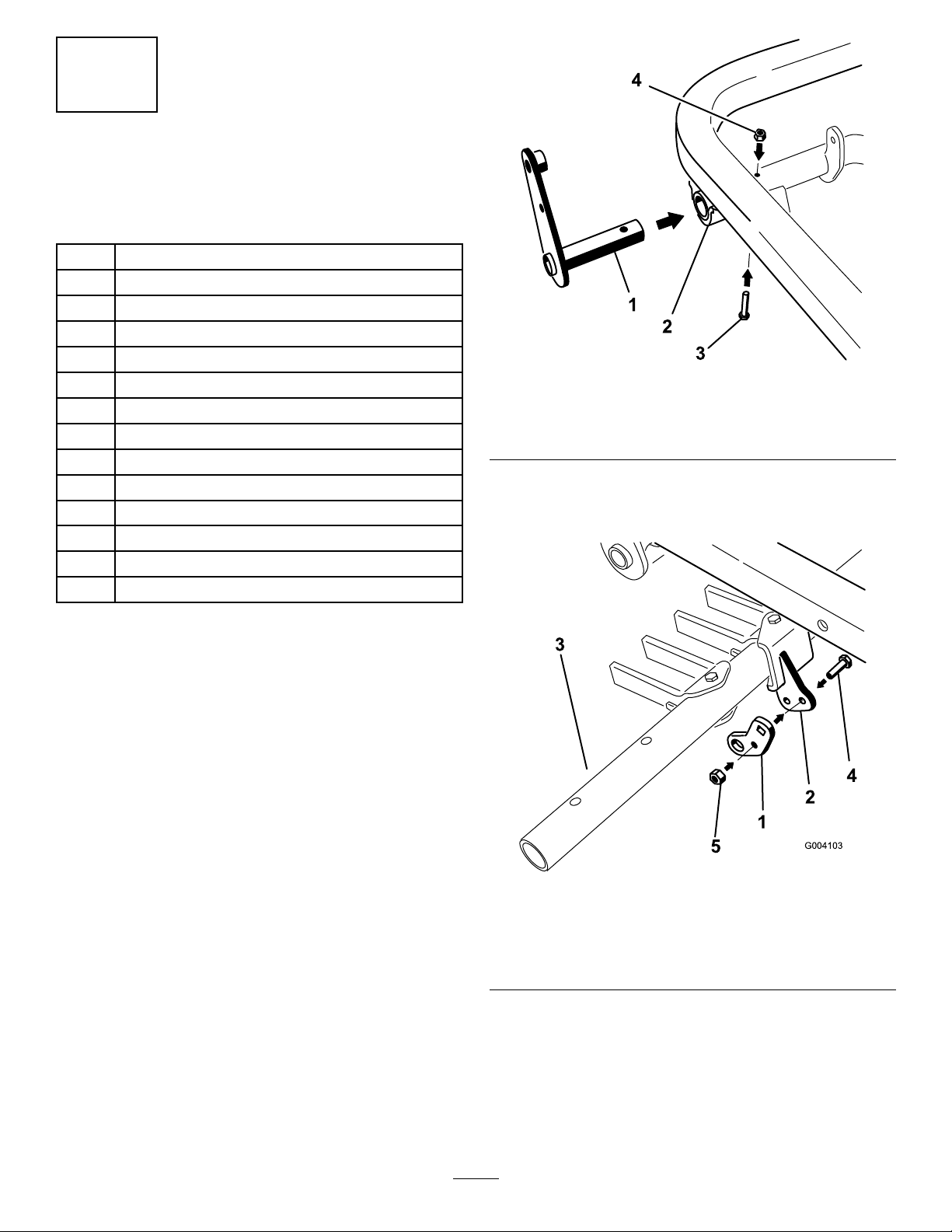
4.Insertthespringrodintotheholeinthespring
bracket,andlooselysecureitwithalocknut(3/8
inch).
Note:Positionthespringrodasshownin
Figure6.
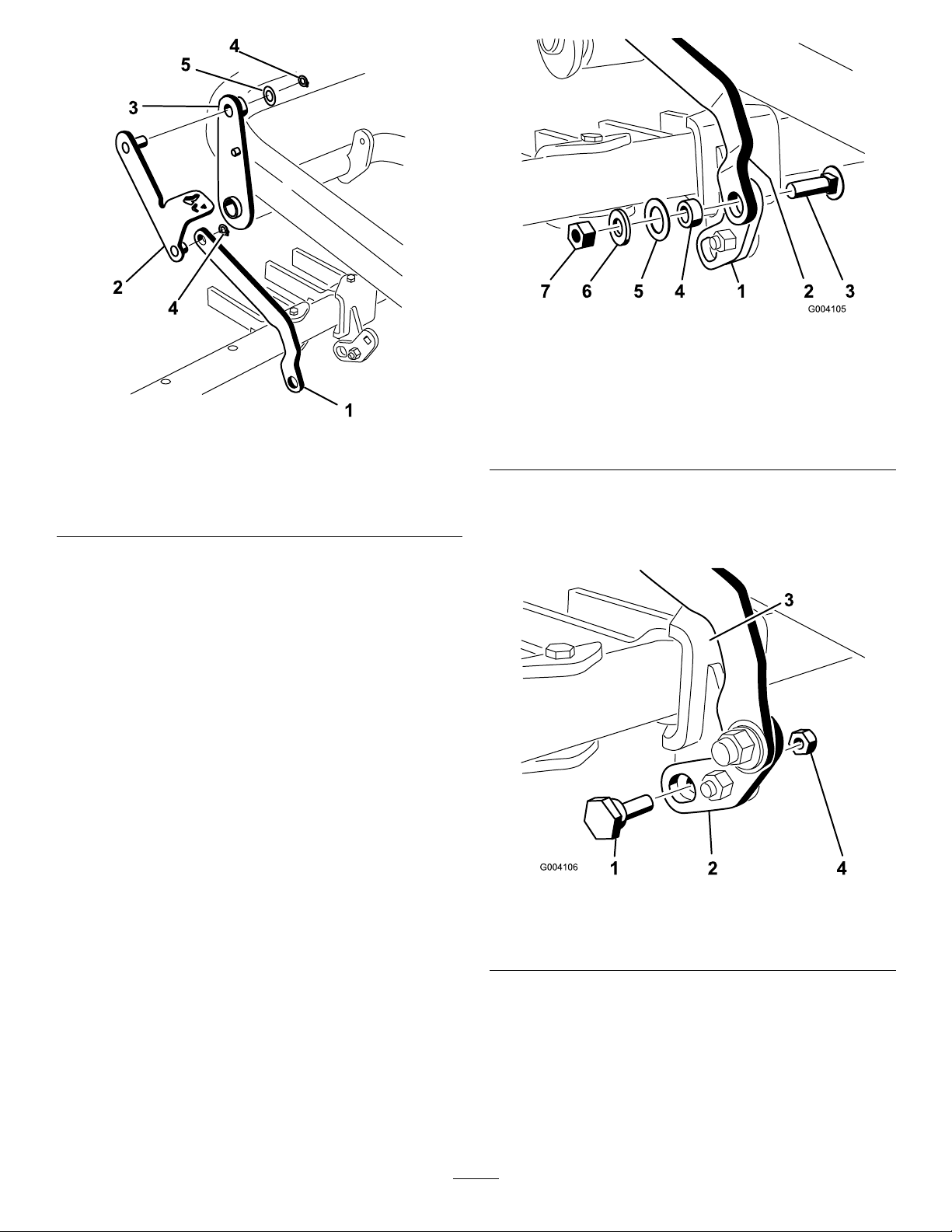
g346051
Figure6
1.Extensionspring4.Frame
2.Springrod5.Springbracket
3.Locknut(3/8inch)6.Bolt(3/8x2-3/4inch)
5.Raisetheleft-handsideofthepivottubetothe
frameandinstallitwithapivottubebracket,2
bolts(3/8x3inch),and2locknuts(3/8inch)
(Figure5).
6.Mountthespringbrackettothefrontframetube
withabolt(3/8x2-3/4inch)andalocknut(3/8
inch).
Note:Positionthespringbracketasshownin
Figure6.
7.Tightenallfasteners,butdonottightenthe
locknutthatsecurethespringrodatthistime.
4
InstallingtheAdjustable
RodAssembly
Partsneededforthisprocedure:
1Adjustablerodassembly
1Bolt(1/2x1-1/2inches)
2Locknut(1/2inch)
Procedure
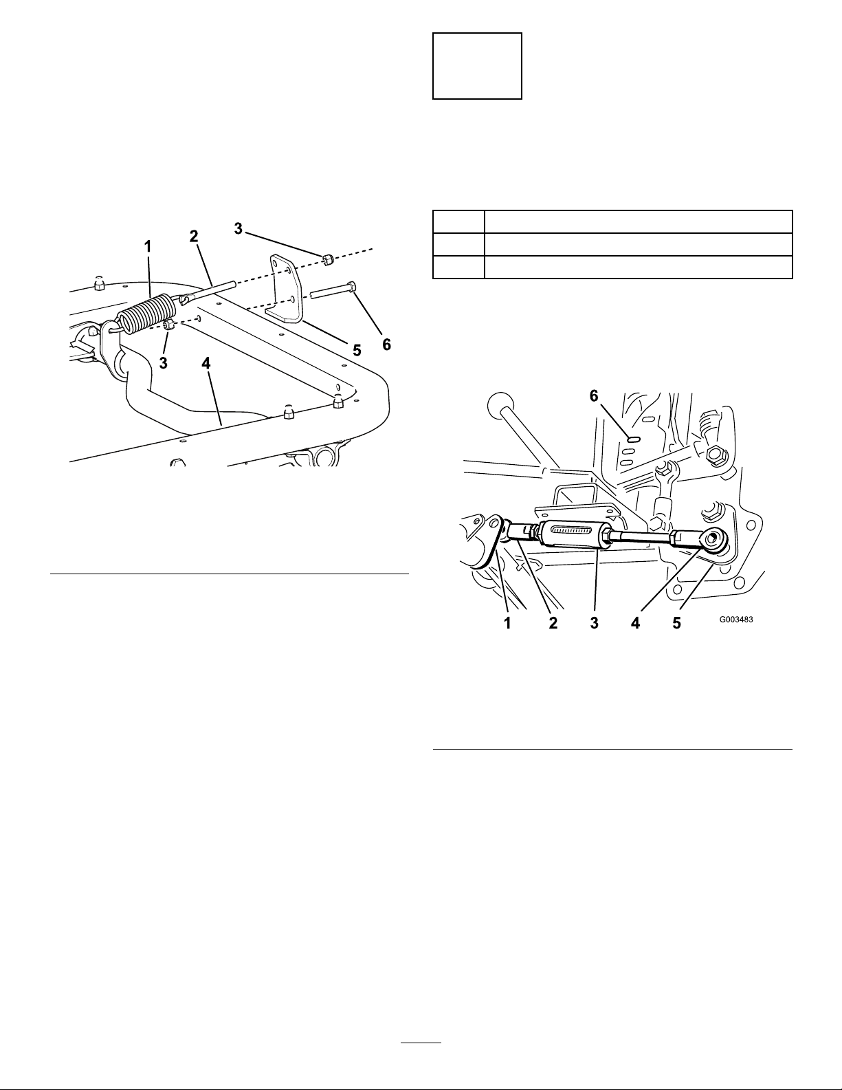
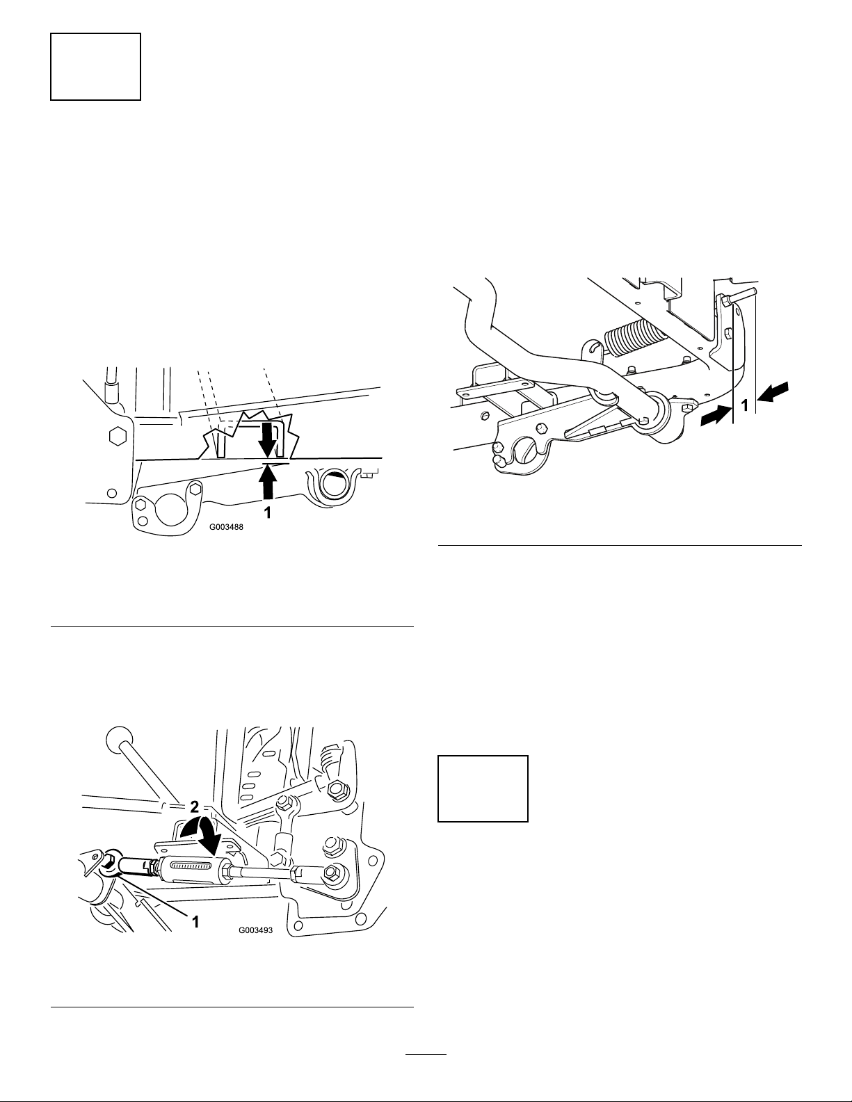
1.Positiontheballjointoftheshortendofthe
adjustablerodassemblytotherightofthe
adjustablerodleveronthepivottube(Figure7).
g003483
Figure7
1.Adjustablerodleveronthe
pivottube
4.Long-endballjoint
2.Short-endballjoint5.Lifthandleassembly
3.Adjustablerod6.Seconddetentposition
2.Movethelifthandletotheseconddetent
positionfromthetop.
3.Placetheballjointonthelongendofthe
adjustablerodassemblyoverthestudonthe
bottomonthelifthandleassemblyandloosely
secureitwithalocknut(1/2inch)(Figure7).
Note:Youcanmovethepivottubeupordown
initsbracketstogainclearanceformounting
theadjustablerod.
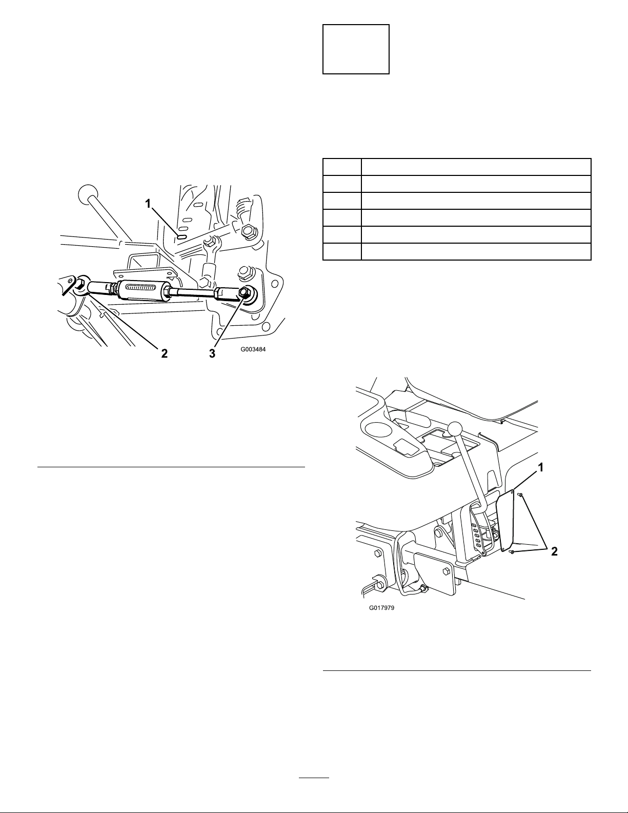
4.Movethelifthandleallthewaydownwardtothe
bottomdetentposition.
5.Movetheballjointontheshortendofthe
adjustablerodaroundtheadjustablerodlever
5