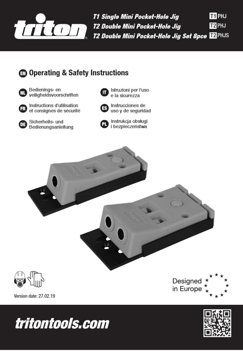
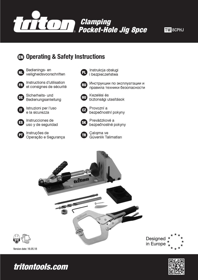
Triton 303468 Assembly instructions

Version date: 27.02.19
tritontools.com
TS Shelf Pin Jig
TS PJ
Operating & Safety Instructions
Bedienings- en
veiligheidsvoorschriften
Instructions d’utilisation
et consignes de sécurité
Sicherheits- und
Bedienungsanleitung
Istruzioni per l’uso
e la sicurezza
Instrucciones de
uso y de seguridad
Instrukcja obsługi
i bezpieczeństwa
303468_Manual.indd 1 27/02/2019 15:31

2
1
3
4
2
56789
303468_Manual.indd 2 27/02/2019 15:31

3
D
B
E
C
A
303468_Manual.indd 3 27/02/2019 15:31

4
EN
Introduction
Thank you for purchasing this Triton product. This manual contains
information necessary for safe and effective operation of this
product. This product has unique features and, even if you are
familiar with similar products, it is necessary to read this manual
carefully to ensure you fully understand the instructions. Ensure all
users of the product read and fully understand this manual.
Product Familiarisation
1. Jig
2. Drill Guide x7
3. Drill Bit
4. Locating Pin
5. Hex Key
6. Depth Collar
7. Clamping Area
8. Joining Hook
9. Joining Pin
Intended Use
Jig for creating locating holes for adjustable shelving units such as
cabinets, bookshelves etc.
Before Use
WARNING: Always adhere to all safety advice and instructions
for any power tool used in conjunction with this product.
Connecting multiple Jigs
Two or more Jigs (1) can be connected using the snap-on system,
to produce a continuous Jig, covering the whole length to be drilled.
1. Line up the ends of Jigs to be joined, at 45o to each other
2. Swivel the Jigs in opposite directions to engage the Joining
Hooks (8) with the Joining Pins (9). Apply enough pressure to
snap into place (Image A)
3. Attach additional Jigs as required
Operation
WARNING: NEVER hold the Jig (1) by hand when drilling, it
must be clamped securely to the workpiece. Failure to do so could
result in misaligned holes, damage to the tool and/or cause serious
personal injury.
1. To set the drill depth place the Drill Bit (3) in one of the Drill
Guides (2) and align the Drill Bit with the edge of the workpiece
(Image B)
2. Place the Depth Collar (6) over the Drill Bit and set the Drill Bit
to the correct depth (Image B)
3. Tighten the grub screw on the Depth Collar using the Hex Key
(5), to lock the Depth Collar in place (Image B)
4. Use the pull-out guides on the underside of the Jig (1) (Image
C) to set the required distance from the edge of the workpiece.
Note: There are 2 sets of guides to allow for 2 different distance
settings
5. Locate the guides against the edge of the workpiece (Image D)
and position the Jig
6. Clamp the Jig in place using the Clamping Area (7) (Image D)
7. Connect a drill (not supplied) to the Drill Bit
8. Place the Drill Bit into one of the Drill Guides until the tip
connects with the workpiece
9. Start the drill and gently drill the hole until the Depth Collar
connects with the Jig (Image D)
Note: Use the drill on the fast setting and maintain a high speed
whilst drilling.
10. Remove the Drill Bit from the Drill Guide and switch off the drill
11. Continue to drill holes using the remaining Drill Guides
12. Remove the clamp and reposition the Jig to continue drilling
the sequence of holes
13. Position the Jig using the Locating Pin (4) through the first Drill
Guide into the last hole in the row of holes just drilled (Image E)
14. Re-clamp the jig and continue drilling the holes
Note: If there is not enough room for the full length of the Jig at
the end of the sequence of drilled holes, then use whichever of the
holes that will position the Jig accordingly.
Note: The Jig can be used without the guides, however, an
alternative method for aligning the Jig will need to be implemented
to ensure accurate alignment of the holes.
Accessories
A full range of accessories including Drill Bits, Locating Pins and
Depth Collars, is available from your Triton stockist.
Maintenance
Keep the Jig clean. Do not allow sawdust to build up around the Jig.
Clean regularly with a soft brush or vacuum, clean resin off with a
suitable solvent
Contact
For technical or repair service advice, please contact the helpline on
(+44) 1935 382 222
Web: tritontools.com/en-GB/Support
Address:
Powerbox
Boundary Way
Lufton Trading Estate
Yeovil, Somerset
BA22 8HZ, United Kingdom
Original Instructions
303468_Manual.indd 4 27/02/2019 15:31

GB
5
NL
Inleiding
Hartelijk dank voor de aankoop van dit Triton-product. Deze
handleiding omvat informatie die nodig is voor een veilig en
efficiënt gebruik van dit product. Dit product is in het bezit van
unieke kenmerken en, zelfs indien u bekend bent met gelijkaardige
producten, is het nodig om deze handleiding aandachtig door te
lezen om er zeker van te zijn dat u de instructies volledig begrijpt.
Zorg ervoor dat alle gebruikers van het product deze handleiding
volledig gelezen en begrepen hebben.
Productonderdelen
1. Mal
2. Boorgeleidingen x 7
3. Boorbit
4. Locatiepen
5. Zeskantsleutel
6. Dieptekraag
7. Klemzone
8. Verbindingshaak
9. Verbindingspen
Voorzien gebruik
Schappen boormal voor het creëren en het lokaliseren van gaten
voor aanpasbare schapeenheden, zoals in kasten, bibliotheken,
enzovoort.
Voorafgaand aan het gebruik
WAARSCHUWING: Respecteer steeds alle
veiligheidswaarschuwingen en - instructies wanneer u gebruik
maakt van elektrisch gereedschap in combinatie van dit product.
Verbinden van meerdere mallen
Twee of meer mallen (1) kunnen verbonden worden door gebruik te
maken van het kliksysteem, teneinde een continue mal te vormen
waarmee de volledige te boren lengte kan worden afgedekt.
1. Lijn de einde van de te verbinden mallen uit, onder een hoek
van 45º ten opzichte van elkaar
2. Draai de mallen in tegengestelde richtingen om
de verbindingshaken (8) samen te brengen met de
verbindingspennen (9). Oefen voldoende ruk uit op het geheel
vast te klikken (Afbeelding. A)
3. Verbind bijkomende mallen naar wens
Werking
WAARSCHUWING: Houd de mal (1) NOOIT in de hand vast
wanneer er geboord wordt; zij dient stevig vast te worden gezet op
het werkstuk. Indien u dat niet doet, kan dat aanleiding geven tot
slecht uitgelijnde gaten, schade aan het gereedschap en/of ernstig
persoonlijk letsel.
1. Om de boordiepte in te stellen, plaatst u het boorbit (3) in
één van de boorgeleidingen (2), en lijnt u het boorbit uit ten
opzichte van de rand van het werkstuk (Afbeelding. B).
2. Plaats de dieptekraag (6) over het boorbit, en stel het boorbit in
op de correcte diepte (Afbeelding. B).
3. Span de stelschroef op de dieptekraag aan met behulp van de
zeskantsleutel (5), teneinde de dieptekraag op de juiste plaats
te vergrendelen (Afbeelding. B).
4. Gebruik de uittrekbare geleidingen aan de onderzijde van de
mal (1) (Afbeelding. C) om de vereiste afstand in te stellen ten
opzichte van de rand van het werkstuk.
Opmerking: Er zijn 2 sets met geleidingen waarmee 2 verschillende
afstanden kunnen ingesteld worden.
5. Plaats de geleidingen tegen de rand van het werkstuk
(Afbeelding. D) en positioneer de mal.
6. Klem de mal op de juiste plaats vast met behulp van de
klemzone (7) (Afbeelding. D).
7. Verbind een boormachine (niet meegeleverd) met het boorbit.
8. Plaats het boorbit in één van de boorgeleidingen tot de punt
contact maakt met het werkstuk.
9. Start de boormachine en boor het gat voorzichtig tot de
dieptekraag verbinding maakt met de mal (Afbeelding. D).
Opmerking: Gebruik de boormachine in de snelle stand en houd
deze snelheid aan tijdens het boren.
10. Verwijder het boorbit uit de boorgeleiding, en schakel de
boormachine uit.
11. Ga verder met het boren van gaten met behulp van de
resterende boorgeleidingen.
12. Verwijder de klem en herpositioneer de mal om verder te gaan
met het boren van de resterende gaten.
13. Positioneer de mal met behulp van de locatiepen (4) door de
eerste boorgeleiding en in het laatste gat van de rij met net
geboorde gaten (Afbeelding. E).
14. Klem de mal opnieuw vast en ga verder met het boren van
gaten.
Opmerking: Indien er niet genoeg ruimte is voor de volledige lengte
van de mal aan het einde van de reeks geboorde gaten, gebruik dan
welk van de gaten dan ook om de mal correct te positioneren.
Opmerking: De mal kan zonder de geleidingen gebruikt worden,
maar een alternatieve werkwijze om de mal uit te lijnen zal dan
gebruikt moeten worden om zeker te zijn van een nauwkeurige
uitlijning van de gaten.
Accessoires
Een heel gamma aan accessoires, met inbegrip van boorbits,
locatiepennen, en dieptekragen, is verkrijgbaar bij uw Triton-
leverancier.
Onderhoud
Houd de schappen boormal zuiver. Laat geen zaagsel accumuleren
rond de mal, maak regelmatig schoon met een zachte borstel
of met vacuüm, en verwijder hars met een daarvoor geschikt
oplosmiddel
Contact
Voor advies in verband met technische zaken of met herstellingen,
gelieve contact op te nemen met (+44) 1935 382 222
Web: tritontools.com/nl-NL/Support
Adres:
Powerbox
Boundary Way
Lufton Trading Estate
Yeovil, Somerset
BA22 8HZ, Verenigd Koninkrijk
Vertaling van de originele instructies
303468_Manual.indd 5 27/02/2019 15:31

ENGBFR
6
Introduction
Nous vous remercions d’avoir choisi cet équipement Triton.
Ces instructions contiennent les informations nécessaires
au fonctionnement efficace et sûr de ce produit. Veuillez lire
attentivement ce manuel pour vous assurer de tirer pleinement
avantage des caractéristiques uniques de votre nouvel équipement.
Gardez ce manuel à portée de main et assurez-vous que tous les
utilisateurs l’aient lu et bien compris avant toute utilisation.
Descriptif du produit
1. Gabarit
2. 7 x Guides de perçage
3. Foret
4. Embout de positionnement
5. Clé hexagonale
6. Bague de profondeur
7. Surface de serrage
8. Raccord “femelle”
9. Raccord “mâle”
Usage conforme
Gabarit de perçage permettant de créer des trous pour les étagères
ajustables comme dans les meubles, les étagères style
« bibliothèque » etc.
Avant Utilisation
AVERTISSEMENT : Toujours adhérer à toutes les consignes
de sécurité et instructions fournies dans le manuel de l’outil
électroportatif utilisé conjointement à ce produit.
Raccordement de plusieurs gabarits
Deux gabarits (1) ou plus peuvent être raccordés les uns aux autres
à l’aide du système « Snap-on » (raccord mâle et femelle), afin de
travailler avec un gabarit rallongé, et ainsi couvrir une plus grande
surface de perçage.
1. Alignez les extrémités des gabarits que vous souhaitez
raccorder, à 45° l’un de l’autre.
2. Pivotez les gabarits dans la direction opposée afin de
d’emboîter les raccords « femelle » (8) sur les raccords « mâle
» (9). Appliquez assez de force pour emboîter les raccords
correctement (Image A).
3. Raccordez d’autres gabarits en fonction de vos besoins.
Instructions d’utilisation
AVERTISSEMENT : NE JAMAIS tenir le gabarit (1) avec les
mains lors du perçage ; le gabarit doit être maintenu par serrage
sur la pièce de travail. Le non-respect de cette consigne peut
entraîner le mauvais alignement des trous, endommager l’outil et/
ou entraîner des blessures graves.
1. Pour configurer la profondeur de perçage, positionnez le foret
(3) dans un des guides de perçage (2) puis alignez le foret avec
le bord de la pièce de travail (Image B).
2. Positionnez la bague de profondeur (6) sur le foret et réglez
celui-ci à la profondeur correcte (Image B).
3. Serrez la vis de la bague de profondeur à l’aide de la clé
hexagonale (5) afin de verrouiller la bague en place (Image B).
4. Utilisez les languettes situées sur le dessous du gabarit (1)
(Image C) afin de configurer la distance requise à partir du bord
de la pièce de travail.
Remarque : le gabarit est équipé de 2 lots de languettes pour
accommoder 2 réglages de distance différents.
5. Positionnez les languettes contre le bord de la pièce de travail
(Image D) puis positionnez le gabarit.
6. Verrouillez le gabarit en place à l’aide d’une pince de serrage
sur la surface de serrage (7) (Image D).
7. Connectez la perceuse (non fournie) au foret.
8. Positionnez le foret dans un des guides de perçage jusqu’à ce
que la pointe entre en contact avec la pièce de travail.
9. Mettez la perceuse en marche et laissez le foret pénétrer
doucement dans la matière jusqu’à ce que la bague de
profondeur vienne se bloquer contre le gabarit (Image B).
Remarque : Utilisez la perceuse son sa vitesse maximale et
maintenez une vitesse de perçage rapide.
10. Retirez le foret du guide de perçage puis éteignez la perceuse.
11. Continuez de percer les trous à l’aide des guides de perçage
restants.
12. Retirez la pince de serrage et repositionnez le gabarit pour
continuer de percer la séquence de trous.
13. Positionnez le gabarit à l’aide de l’embout de positionnement
(4) à travers le premier guide de perçage, à travers le dernier
trou de la rangée que vous venez de percer (Image E).
14. Repositionnez la pince de serrage sur la surface de serrage,
puis continuez de percer vos trous.
Remarque : S’il n’y a pas assez de place à la fin de la séquence de
trous pour le gabarit entier, utilisez le trou le mieux adapté.
Remarque : Le gabarit peut être utilisé sans les languettes.
Cependant, une méthode alternative d’alignement du gabarit devra
être utilisée pour assurer l’alignement précis des trous.
Accessoires
• Une grande variété d’accessoires, y compris des forets, des
embouts de positionnement et des bagues de profondeur, est
disponible auprès de votre revendeur Triton.
Entretien
Gardez votre gabarit pour étagère propre en permanence. Ne laissez
pas la poussière et les copeaux s’accumuler autour du gabarit.
Nettoyez régulièrement à l’aide d’une brosse souple, d’un aspirateur
ou d’air comprimé, et nettoyez la résine à l’aide d’un solvant
approprié.
Contact
Pour tout conseil technique ou réparation, veuillez nous contacter :
- Téléphone : (+44) 1935 382 222
- Site web : www.tritontools.com/fr-FR/Support
- Adresse : Powerbox
Boundary Way
Lufton Trading Estate
Yeovil, Somerset
BA22 8HZ, United Kingdom (Royaume-Uni)
Traduction des instructions originales
303468_Manual.indd 6 27/02/2019 15:31

GBDE
7
Übersetzung der Originalbetriebsanleitung
Bohrschablone (1) (Abb. C) lässt sich der erforderliche Abstand
zur Werstückkante festlegen.
Hinweis: Die Bohrschablone ist mit Führungslaschen zweier
Größen ausgestattet, die unterschiedliche Abstandseinstellungen
ermöglichen.
5. Bringen Sie die Bohrschablone in Position, so dass die
Führungslaschen bündig entlang der Werkstückkante (Abb. D)
liegen.
6. Spannen Sie die Bohrschablone mithilfe einer Werkstückzwinge
innerhalb des Spannbereichs (7) (Abb. D) fest.
7. Setzen Sie den Bohrer in die Bohrmaschine (nicht mitgeliefert)
ein und befestigen Sie ihn.
8. Führen Sie die Bohrerspitze in eine der Bohrführungen bis
diese das Werkstück berührt.
9. Schalten Sie die Bohrmaschine ein und führen Sie die
Bohrerspitze langsam in das Werkstück, bis der Tiefenanschlag
an der Bohrschablone anschlägt (Abb. D).
Hinweis: Bohren Sie bei hoher Drehzahl und halten Sie diese
Geschwindigkeit während des gesamten Bohrdurchgangs.
10. Entnehmen Sie den Bohrer aus der Bohrführung und schalten
Sie die Bohrmaschine aus.
11. Bohren Sie weitere Löcher mit den restlichen Bohrführungen.
12. Entfernen Sie die Klemmzwinge und positionieren Sie die
Bohrschablone erneut, um die Lochreihenfolge fortzusetzen.
13. Positionieren Sie die Bohrschablone, indem Sie den Fixierstift
(4) durch die letzte Bohrführung der Bohrschablone in das
letzte Loch der gerade gebohrten Lochreihe stecken (Abb. E).
14. Spannen Sie die Bohrschablone erneut fest und bohren Sie die
verbleibenden Löcher.
Hinweis: Wenn am Ende der Lochreihe nicht genügend Platz
vorhanden ist, um die Schablone der ganzen Länge nach
anzusetzen, dann verwenden Sie die entsprechende Bohrführung,
die es ermöglicht die Bohrschablone zu positionieren.
Hinweis: Die Bohrschablone kann auch ohne Führungslaschen
verwendet werden, allerdings muss dann eine alternative Methode
zum Ausrichten der Bohrschablone implementiert werden, um
exakte Abstände der Lochreihe gewährleisten zu können.
Zubehör
Ein umfassendes Zubehörsortiment einschließlich verschiedener
Bohrer, Fixierstifte und Tiefeneinstellringe ist über Ihren Triton-
Fachhändler erhältlich.
Wartung und Pflege
Halten Sie Ihre Bohrschablone in einem sauberen Zustand.
Vermeiden Sie, dass sich Sägemehl um die Bohrschablone herum
ansammelt. Reinigen Sie das Gerät regelmäßig mit einer weichen
Bürste, einem Staubsauger oder ggf. mit Druckluft und entfernen
Sie Harz mit einem geeigneten Lösungsmittel.
Kontakt
Informationen zu Reparatur- und Kundendiensten erhalten Sie unter
der Rufnummer (+44) 1935/382222.
Webseite: tritontools.com/de-DE/Support
Postanschrift:
Powerbox
Boundary Way
Lufton Trading Estate
Yeovil, Somerset
BA22 8HZ
Großbritannien
Einführung
Vielen Dank, dass Sie sich für dieses Triton-Werkzeug entschieden
haben. Diese Anleitung enthält wichtige Informationen für das
sichere und effektive Arbeiten mit diesem Produkt. Bitte lesen Sie
diese Anleitung sorgfältig durch, um den größtmöglichen Nutzen
aus dem einzigartigen Design dieses Produkts ziehen zu können.
Bewahren Sie diese Anleitung griffbereit auf und sorgen Sie dafür,
dass alle Benutzer dieses Geräts sie gelesen und verstanden haben.
Geräteübersicht
1. Bohrschablone
2. Bohrführung x 7
3. Bohrer
4. Fixierstift
5. Sechskantschlüssel
6. Tiefeneinstellring
7. Spannbereich
8. Verbindungseinkerbung
9. Verbindungsnase
Bestimmungsgmäße
Verwendung
Bohrschablone für optimale Anfertigung sauberer und exakter
Bohrlöcher für Regalböden in Regalen und Schränken.
Vor Inbetriebnahme
WARNUNG! Befolgen Sie stets die Sicherheitshinweise und die
Bedienungsanleitung des Elektrowerkzeugs, das in Verbindung mit
diesem Produkt verwendet wird.
Verwendung mehrerer Bohrschablonen
Dank des Einrastsystems lassen sich zwei oder mehrere
Bohrschablonen (1) miteinander verbinden, um eine durchgehende
Bohrvorrichtung zu erzeugen, die die gesamte zu bohrende Länge
abdeckt.
1. Richten Sie die zu verbindenden Bohrschablonenenden in einem
Winkel von 45° aufeinander aus.
2. Führen Sie die Bohrschablone in entgegengesetzten Richtungen,
um die Verbindungseinkerbungen (8) mit den Verbindungsnasen
(9) zusammenzufügen. Üben Sie genug Druck aus, um die Teile
einrasten zu lassen (Abb. A).
3. Verbinden Sie zusätzliche Bohrschablonen bei Bedarf.
Bedienung
WARNUNG! Halten Sie während des Bohrens die
Bohrschablone (1) NIEMALS mit der Hand fest; diese muss
unbedingt mit Hilfe einer geeigneten Spannvorrichtung an einer
Werkbank befestigt werden. Bei Nichtbeachtung können das
Werkzeug beschädigt und/oder schwere Verletzungen verursacht
werden.
1. Zum Einstellen der Bohrtiefe setzen Sie den Bohrer (3) in eine
der Bohrführungen (2) und richten ihn mit der Werkstückkante
aus (Abb. II).
2. Schieben Sie den Tiefeneinstellring (6) in der gewünschten
Bohrtiefe auf den Bohrer auf (Abb. B).
3. Ziehen Sie die Madenschraube am Tiefeneinstellring mithilfe
des Sechskantschlüssels (5) fest (Abb. B).
4. Mit den ausklappbaren Führungslaschen an der Unterseite der
303468_Manual.indd 7 27/02/2019 15:31

ENGBIT
8
Traduzione delle istruzioni originali
Introduzione
Grazie per aver acquistato questo prodotto Triton. Questo manuale
contiene le informazioni necessarie per un funzionamento sicuro
ed efficace di questo prodotto. Questo prodotto ha caratteristiche
uniche e, anche se si ha familiarità con prodotti simili, è necessario
leggere attentamente questo manuale per assicurarsi di
comprendere a pieno le istruzioni. Assicurarsi che tutti gli utenti del
prodotto leggano e comprendano questo manuale.
Familiarizzare con il prodotto
1. Dima
2. Guida per trapano x7
3. Punta da trapano
4. Perno di posizionamento
5. Chiave esagonale
6. Collare di profondità
7. Area di morsa
8. Gancio connettore
9. Perno di collegamento
Uso Previsto
DIma per creare fori di posizionamento per scaffali regolabili come
armadi, librerie ecc.
Prima dell’uso
ATTENZIONE: Attenersi sempre a tutti i consigli e le istruzioni
di sicurezza relativi a qualsiasi utensile elettrico utilizzato in
combinazione con questo prodotto.
Collegare più dime insieme
É possibile collegare due o più dime (1) utilizzando il sistema a
gancio, così da produrre una dima continua, coprendo l’intera
lunghezza da perforare.
1. Allineare le estremità delle dime da unire, ad un’inclinazione di
45°
2. Ruotare le dime in direzioni opposte per far sì che i ganci
connettori (8) si colleghino ai perni di collegamento (9).
Applicare una pressione sufficiente per farli scattare in
posizione (Immagine A)
3. Aggiungere ulteriori dime se richiesto
Funzionamento
ATTENZIONE: non tenere MAI la dima (1) in mano durante la
foratura, questa deve essere fissata saldamente al pezzo. In caso
contrario, potrebbero crearsi fori non allineati, o verificarsi danni
all’utensile e/o gravi lesioni personali.
1. Per impostare la profondità della punta, posizionare la punta
del trapano (3) in una delle guide del trapano (2) e allineare la
punta del trapano con il bordo del pezzo (Immagine B)
2. Collocare il collare di profondità (6) sulla punta del trapano e
impostare il trapano alla profondità corretta (Immagine B)
3. Stringere la vite senza testa sul colletto di profondità utilizzando
la chiave esagonale (5), per bloccare il collare di profondità in
posizione (Immagine B)
4. Utilizzare le guide estraibili sul lato inferiore della dima (1)
(Immagine C)per impostare la distanza richiesta dal bordo del
pezzo.
Nota: ci sono 2 set di guide per consentire 2 diverse impostazioni
di distanza
5. Posizionare le guide contro il bordo del pezzo (Immagine D) e
posizionare la dima
6. Bloccare la dima in posizione utilizzando l’area di morsa (7)
(Immagine D)
7. Inserire la punta al trapano (non incluso)
8. Posizionare la punta del trapano in una delle guide di
perforazione finché la punta non tocca il pezzo
9. Avviare il trapano e praticare delicatamente il foro finché il
collare di profondità non tocca la dima (Immagine D)
Nota: utilizzare il trapano sull’impostazione rapida e mantenere
un’alta velocità durante la perforazione.
10. Rimuovere la punta del trapano dalla guida e spegnere
l’utensile
11. Continuare a praticare i fori usando le rimanenti guide di
perforazione
12. Rimuovere il morsetto e riposizionare la dima per continuare a
praticare la sequenza di fori
13. Collocare la dima utilizzando il perno di posizionamento (4)
attraverso la prima guida di perforazione nell’ultimo foro della
fila appena perforata (Immagine E)
14. Applicare di nuovo la morsa alla dima e continuare a praticare i
fori
Nota: se non ci fosse abbastanza spazio per l’intera lunghezza
della dima alla fine della sequenza di fori, posizionare la dima di
conseguenza, usando il foro più appropriato.
Nota: la dima può essere utilizzata senza le guide, tuttavia per
garantire un allineamento accurato dei fori, sarà necessario
utilizzare un metodo alternativo per posizionare correttamente
la dima.
Accessori
Una gamma completa di accessori, tra cui punte da trapano, perni
di posizionamento e collari di profondità, è disponibile presso il
proprio rivenditore Triton.
Manutenzione
Mantieni pulita la dima. Non lasciare che la segatura si accumuli
attorno alla dima. Pulire regolarmente con una spazzola morbida,
un sitema aspirapolvere o aria compressa, pulire la resina con un
solvente adatto
Contatti
Per consigli tecnici e per eventuali riparazioni, si prega di contattare
il nostro servizio di assistenza telefonico al numero (+44) 1935
382 222
Sito web: tritontools.com/it-IT/Support
Indirizzo:
PowerBox
Boundary Way
Lufton Trading Estate
Yeovil, Somerset
BA22 8HZ, Regno Unito
303468_Manual.indd 8 27/02/2019 15:31

GBES
9
Traducción del manual original
Introducción
Gracias por haber elegido esta herramienta Triton. Estas
instrucciones contienen la información necesaria para utilizar este
producto de forma segura y eficaz. Lea atentamente este manual
para obtener todas las ventajas y características únicas de su nueva
herramienta. Conserve este manual a mano y asegúrese de que
todas las personas que utilicen esta herramienta lo hayan leído y
entendido correctamente.
Características del producto
1. Guía
2. Agujeros guía (x 7)
3. Broca
4. Pasador
5. Llave hexagonal
6. Tope de profundidad
7. Superficie de sujeción
8. Ranura para ensamblar
9. Conector para ensamblar
Aplicaciones
Guía indicada para realizar agujeros en estanterías, armarios,
librerias, etc.
Antes de usar
ADVERTENCIA: Siga siempre todos los consejos e instrucciones
de seguridad para cualquier herramienta eléctrica utilizada junto
con este producto.
Ensamble de varias guías
Es posible conectar más de una guía (1) utilizando el sistema de
montaje integrado para alcanzar la longitud requerida.
1. Alinee los extremos de las guías a ensamblar y colóquelas en
un ángulo de 45o.
2. Gire las guías en sentido opuesto para montar la ranura
(8) sobre el conector (9). Presione para fijar ambas piezas
conjuntamente (Imagen A).
3. Instale guías adicionales según requiera.
Funcionamiento
ADVERTENCIA: NUNCA sujete la guía (1) con las manos cuando
esté perforando. Sujete la guía de forma segura sobre una pieza
o banco de trabajo. No seguir estas indicaciones podría causar
lesiones personales y dañar esta herramienta.
1. Coloque la broca (3) en uno de los agujeros guía (2) y alinee la
broca con el borde de la pieza de trabajo (Imagen B).
2. Bloquee el collar de profundidad (6) en la broca a la
profundidad de perforación requerida (Imagen B).
3. Apriete el tornillo prisionero en el tope de profundidad
utilizando la llave hexagonal (5) para ajustar el tope de
profundidad a la profundidad requerida (Imagen B).
4. Utilice las guías situadas en la parte inferior de la guía (1)
(Imagen C) para ajustar la distancia requerida desde el borde
de la pieza de trabajo.
Nota: Existen 2 tipos de guías diferentes para 2 ajustes de distancia
diferentes.
5. Coloque las guías inferiores contra el borde de la pieza de
trabajo (Imagen D) y ajuste la posición de la guía.
6. Utilice la superficie de sujeción (7) para sujetar la guía (Imagen
D).
7. Introduzca la broca en el taladro (no suministrado).
8. Introduzca la pinta de la broca escalonada dentro del agujero
guía hasta que la punta entre en contacto con la pieza de
trabajo.
9. Comience a perforar lentamente hasta que el tope de
profundidad de la broca entre en contacto con la guía (Imagen
D).
Nota: Use el taladro en la configuración rápida y mantenga una alta
velocidad mientras esté perforando.
10. Retire la broca fuera de la guía y apague el taladro.
11. Realice los siguientes agujeros.
12. Retire la abrazadera y vuelva a colocar la guía en la posición
requerida para realizar agujeros adicionales.
13. Coloque el pasador (4) en el último orificio guía de la primera
guía para posicionar la guía (Imagen E).
14. Vuelva a sujetar la guía y realice los siguientes agujeros.
Nota: Utilice los últimos orificios para realizar los agujeros si no
dispone de suficiente espacio para ensamblar la última guía.
Nota: Esta guía para taladro puede utilizarse con o sin las guías
incorporadas. Utilice un método adicional para alinear la guía si
es necesario.
Accesorios
Existen gran variedad de accesorios, brocas, pasadores y topes de
profundidad para esta herramienta disponibles en su distribuidor
Triton.
Mantenimiento
Mantenga la guía siempre limpia. No deje que se acumule el polvo
o las virutas en la guía. Limpie este producto con un cepillo suave,
aspiradora o aire comprimido. Limpie los restos de resina con un
disolvente apropiado.
Contacto
Servicio técnico de reparación – Tel: (+44) 1935 382 222
Web: tritontools.com/es-ES/Support
Dirección:
Powerbox
Boundary Way
Lufton Trading Estate
Yeovil, Somerset
BA22 8HZ, Reino Unido
303468_Manual.indd 9 27/02/2019 15:31

ENGBEPL
10
Tłumaczenie oryginalnej instrukcji
Wprowadzenie
Dziękujemy za zakup produktu marki Triton. Niniejsza
instrukcja obsługi zawiera informacje niezbędne dla
bezpiecznej i wydajnej obsługi produktu. Produkt posiada
szereg unikalnych funkcji, dlatego też, nawet jeśli jesteś
zaznajomiony z podobnymi produktami, przeczytanie tego
podręcznika jest niezbędne w celu pełnego zrozumienia
instrukcji obsługi. Upewnij się, że wszyscy użytkownicy
narzędzia przeczytali i w pełni zrozumieli instrukcję
obsługi.
Przedstawienie produktu
1. Przyrząd wiertarski
2. Prowadnica wiertła x 7
3. Wiertło
4. Bolec ustalający
5. Klucz sześciokątny
6. Kołnierz głębokościowy
7. Obszar zaciskowy
8. Szczelina łącząca
9. Zaczep łączący
Zamierzone zastosowanie
Przyrząd do wykonywania otworów na kołki do
instalowania półek z regulacją wysokości w szafkach,
regałach itp.
Przygotowanie do eksploatacji
OSTRZEŻENIE: W przypadku korzystania z
elektronarzędzi należy zawsze przestrzegać zaleceń
bezpieczeństwa i instrukcji danego narzędzia.
Łączenie wielu uchwytów
Istnieje możliwość połączenia dwóch lub większej liczby
przyrządów (1) za pomocą systemu zatrzaskowego, co
pozwoli na uzyskanie przyrządu rozciągającego się na
całą długość wierconego obszaru.
1. Ustawić końce łączonych przyrządów pod kątem 45o
względem siebie.
2. Obrócić przyrządy w przeciwnych kierunkach celem
połączenia szczelin łączących (8) z zaczepami
łączącymi (9). Zastosować odpowiedni nacisk, aby
połączyć elementy w odpowiednim położeniu
(zdjęcie A).
3. Przymocować dalsze przyrządy zgodnie z
zapotrzebowaniem.
Obsługa
OSTRZEŻENIE: NIGDY nie przytrzymywać przyrządu
(1) dłonią podczas wiercenia. Musi on być odpowiednio
zaciśnięty na przedmiocie obróbki. Nieprzestrzeganie
tego zalecenia może spowodować wykonanie
niewyrównanych otworów, uszkodzenie narzędzia i/lub
poważne obrażenia ciała.
1. Aby ustawić głębokość wiercenia, umieścić wiertło
(3) w jednej z prowadnic wiertła (2) i wyrównać je z
krawędzią detalu (zdjęcie B).
2. Umieścić kołnierz głębokościowy (6) na wiertle i
ustawić wiertło na wybraną głębokość (zdjęcie B).
3. Dokręcić wkręt dociskowy na kołnierzu głębokościowym
za pomocą klucza sześciokątnego (5) celem
unieruchomienia kołnierza w położeniu (zdjęcie B).
4. Za pomocą prowadnic wysuwanych spod spodu
przyrządu (1) (zdjęcie C) ustawić wybraną odległość od
krawędzi detalu.
Uwaga: Dostępne są 2 zestawy prowadnic pozwalające na
kongurację 2 różnych ustawień odległości.
5. Umieścić prowadnice przy krawędzi detalu (zdjęcie D) i
ustawić przyrząd.
6. Zacisnąć przyrząd w położeniu za pośrednictwem
obszaru zaciskowego (7) (zdjęcie D).
7. Przymocować wiertarkę (nie w zestawie) do wiertła.
8. Umieścić wiertło w jednej z prowadnic wiertła, aż do
zetknięcia jego końcówki obrabianym detalem.
9. Uruchomić wiertarkę i delikatnie wywiercić otwór aż do
zetknięcia kołnierza głębokościowego z przyrządem
(zdjęcie D).
Uwaga: Wiertarka powinna pracować z wysoką prędkością i
zachowywać ją podczas wiercenia.
10. Wyjąć wiertło z prowadnicy i wyłączyć wiertarkę.
11. Kontynuować wiercenie otworów przy użyciu
pozostałych prowadnic.
12. Zdjąć zacisk i przesunąć przyrząd, aby wywiercić kolejny
szereg otworów.
13. Ustawić przyrząd za pomocą bolca ustalającego (4)
umieszczonego w pierwszej prowadnicy wiertła i w
ostatnim otworze dopiero, co wywierconego szeregu
otworów (zdjęcie E).
14. Ponownie przymocować przyrząd i kontynuować
wiercenie otworów.
Uwaga: Jeśli po sekwencji wywierconych otworów nie ma
wystarczającej ilości miejsca na to, by zmieścić cały przyrząd
na detalu, należy użyć wcześniejszego otworu, aby zmieścić
przyrząd na detalu.
Uwaga: Przyrząd może być używany bez prowadnic,
jednak należy wtedy zastosować alternatywną metodę
wyrównywania przyrządu, aby zapewnić dokładne
wyrównanie otworów.
Akcesoria
Pełny asortyment akcesoriów, w tym wierteł, bolców
ustalających i kołnierzy głębokościowych, jest dostępny u
dystrybutorów produktów marki Triton.
Konserwacja
Utrzymywać przyrząd w czystości. Nie dopuszczać do
gromadzenia się pyłu wokół przyrządu. Regularnie czyścić
przyrząd miękką szmatką lub odkurzaczem. Usuwać żywicę
za pomocą odpowiedniego rozpuszczalnika.
Kontakt
W celu uzyskania porady technicznej lub naprawy skontaktuj
się z infolinią pod numerem (+44) 1935 382 222.
Strona internetowa: tritontools.com/pl-PL/Support
Adres:
Powerbox
Boundary Way
Lufton Trading Estate
Yeovil, Somerset
BA22 8HZ, Wielka Brytania
303468_Manual.indd 10 27/02/2019 15:31

11
303468_Manual.indd 11 27/02/2019 15:31

303468_Manual.indd 12 27/02/2019 15:31
Table of contents
Languages:
Other Triton Tools manuals

Triton
Triton T1 Assembly instructions

Triton
Triton AWA200 Quick guide

Triton
Triton SJA 470 Quick guide

Triton
Triton T4 PHJ Assembly instructions

Triton
Triton T3 Assembly instructions

Triton
Triton TWSMPJ Assembly instructions

Triton
Triton DCA 250 Quick guide

Triton
Triton TR281928 Assembly instructions

Triton
Triton Pocket-Hole Jig 7pce Assembly instructions

Triton
Triton ETA 300 Quick guide
Popular Tools manuals by other brands

Ingersoll-Rand
Ingersoll-Rand QE4 Series instructions

Parkside
Parkside PDT 40 D3 Translation of the original instructions

Logosol
Logosol TREE PUSHER user manual

Silony Medical
Silony Medical VERTICALE Navigation manual

Roughneck
Roughneck 28480 owner's manual

Roach Conveyors
Roach Conveyors 192CDLR owner's manual