Toro 7264 User manual

Form No. 3356-911 Rev B
Workman® 1110 Utility VehicleModel No. 07264 —Serial No. 270000001 and Up
Model No. 07264TC —Serial No. 270000001 and Up
Register your product at www.Toro.com Original Instructions (EN)

Warning
CALIFORNIA
Pr oposition 65 W ar ning
T he engine exhaust fr om this pr oduct
contains chemicals kno wn to the State of
Calif or nia to cause cancer , bir th defects, or
other r epr oducti v e har m.
Important: T his engine is not equipped
with a spar k ar r ester muf fler . It is a
violation of Calif or nia Public R esource Code
Section 4442 to use or operate the engine
on an y f or est-co v er ed, br ush-co v er ed, or
g rass-co v er ed land. Other states or federal
ar eas may ha v e similar la ws.
T his spark ignition system complies with Canadian
ICES-002
T he enclosed Engine Owner’ s Man ual is
supplied f or inf or mation r egarding the US
En vir onmental Pr otection Agency (EP A) and
the Calif or nia Emission Contr ol R egulation of
emission systems, maintenance, and w ar ranty .
R eplacements may be order ed thr ough the
engine man uf actur er .
Introduction
R ead this infor mation carefully to lear n ho w to
operate and maintain y our product properly and
to a v oid injur y and product damag e . Y ou are
responsible for operating the product properly
and safely .
Y ou ma y contact T oro directly at www .T oro .com
for product and accessor y infor mation, help
finding a dealer , or to register y our product.
W henev er y ou need ser vice , g en uine T oro par ts ,
or additional infor mation, contact an A uthorized
Ser vice Dealer or T oro Customer Ser vice and ha v e
the model and serial n umbers of y our product
ready . Figure 1 identifies the location of the model
and serial n umbers on the product. W rite the
n umbers in the space pro vided.
Figure 1
1. Model and serial number location
Model No.
Serial No.
T his man ual identifies potential hazards and has
safety messag es identified b y the safety aler t
symbol ( Figure 2 ), whic h signals a hazard that ma y
cause serious injur y or death if y ou do not follo w
the recommended precautions .
Figure 2
1. Safety alert symbol
T his man ual uses 2 other w ords to highlight
infor mation. Impor tant calls attention to special
mec hanical infor mation and Note emphasizes
g eneral infor mation w or th y of special attention.
© 2005—The Toro® Company8111 Lyndale Avenue SouthBloomington, MN 55420
2
Contact us at www.Toro.com.
Printed in the USA.All Rights Reserved

Contents
Introduction .......................................................2
Safety ..................................................................4
Safe Operating Practices . . . . . . . . . . . . . . . . . . . . . . 4
Before Operating .................................4
Operation ............................................5
Maintenance ........................................8
Sound Pressure ....................................8
Vibration .............................................8
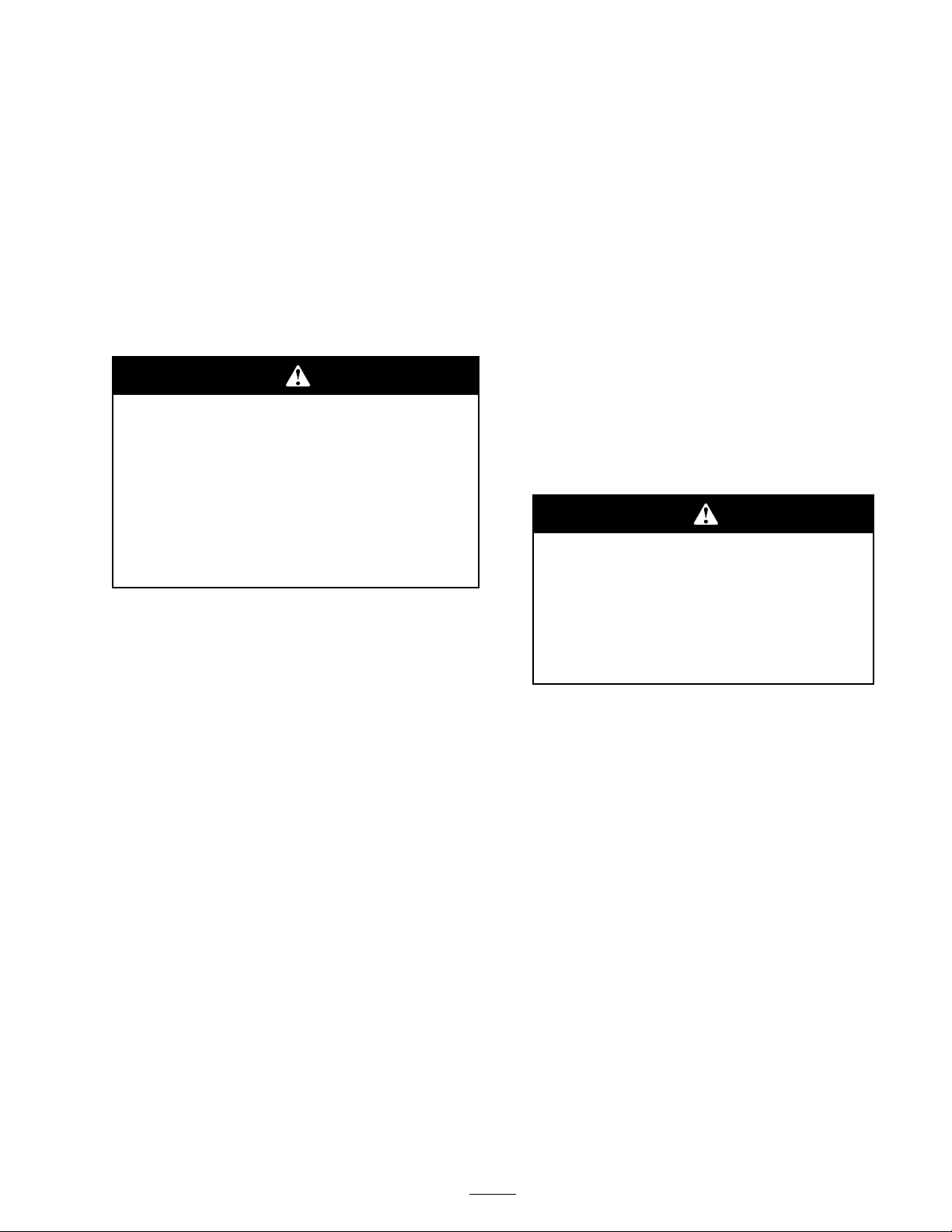
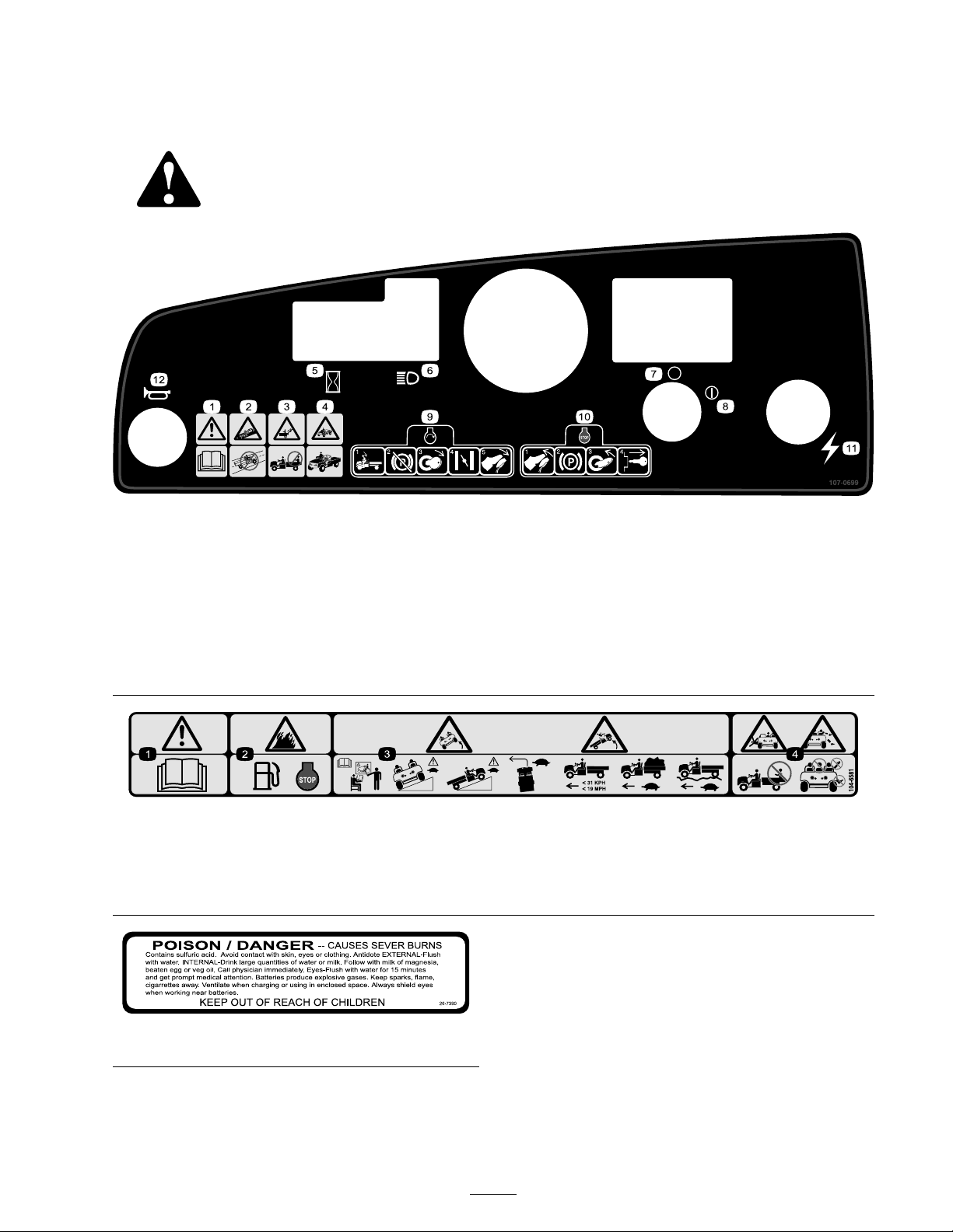
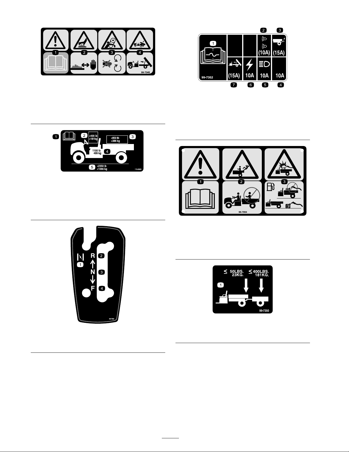
Safety and Instr uctional Decals . . . . . . . . . . . . 9
Setup ................................................................ 11
1 Installing the W heels . . . . . . . . . . . . . . . . . . . . . . . 11
2 Installing the Steering W heel . . . . . . . . . . . 12
3 Installing the Bumper . . . . . . . . . . . . . . . . . . . . . . 12
4 Installing the Seats .......................... 13
5 Installing the Hitc h ......................... 13
6 Installing the Carg o Bo x . . . . . . . . . . . . . . . . . . 14
7 Acti v ating the Batter y . . . . . . . . . . . . . . . . . . . . . . 15
8 Adjusting the F ront W heel
T oe-in ............................... 15
9 R eading the Man ual and Viewing
the Safety Video . . . . . . . . . . . . . . . . . 16
Product Ov er view ............................................. 18
Controls ........................................... 18
Specifications ................................... 21
Operation .......................................................... 22
T hink Safety First .............................. 22
Pre-Star ting Chec ks ........................... 22
Chec king the Engine Oil . . . . . . . . . . . . . . . . . . . . 22
Chec king the Brak e Fluid
Lev el ................................. 22
Chec king the Tire Pressure . . . . . . . . . . . . . . . . . 22
Adding Fuel ...................................... 23
Chec king the T ransmission Oil
Lev el ................................. 24
Star ting the Engine ............................ 24
Stopping the V ehicle .......................... 24
P arking the V ehicle ............................ 24
Operating the Carg o Bo x . . . . . . . . . . . . . . . . . . . 24
Breaking in a New V ehicle . . . . . . . . . . . . . . . . . . 25
Loading the Carg o Bo x . . . . . . . . . . . . . . . . . . . . . . 26
T ranspor ting the V ehicle . . . . . . . . . . . . . . . . . . . . 26
T o wing the V ehicle ............................ 26
T o wing a T railer ................................. 27
Maintenance ...................................................... 28
R ecommended Maintenance
Sc hedule(s) ............................... 28
Daily Maintenance Chec klist . . . . . . . . . . . . . . 29
Premaintenance Procedures . . . . . . . . . . . . . . . . . . . . . . . 30
Maintaining the V ehicle under
Special Operating
Conditions ........................ 30
J ac king the V ehicle ............................. 30
Lubrication ................................................ 30
Adding Grease .................................. 30
Engine Maintenance .................................. 31
Ser vicing the Air Cleaner . . . . . . . . . . . . . . . . . . . 31
Ser vicing the Engine Oil . . . . . . . . . . . . . . . . . . . . 32
Ser vicing the Spark Plug . . . . . . . . . . . . . . . . . . . . 33
Fuel System Maintenance .......................... 33
Inspecting Fuel Lines and
Connections ...................... 33
R e placing the Fuel Filter . . . . . . . . . . . . . . . . . . . . 33
Electrical System Maintenance . . . . . . . . . . . . . . . . . . . 34
R e placing the Fuses ........................... 34
R e placing the Headlights . . . . . . . . . . . . . . . . . . . 34
Ser vicing the Batter y .......................... 34
Dri v e System Maintenance . . . . . . . . . . . . . . . . . . . . . . . . . 36
Chec king and Adjusting
Neutral .............................. 36
Inspecting the Tires ........................... 37
Adjusting the F ront
Suspension ........................ 37
Adjusting F ront W heel T oe-In . . . . . . . . . . . 38
Maintaining the Primar y Dri v e
Clutc h ............................... 39
Changing the T ransaxle Fluid . . . . . . . . . . . . . 40
Cooling System Maintenance . . . . . . . . . . . . . . . . . . . . . 40
Cleaning the Engine Cooling
Areas ................................. 40
Brak e Maintenance .................................... 41
Inspecting the Brak es ......................... 41
Chec king the Brak e Fluid
Lev el ................................. 41
Adjusting the P arking Brak e . . . . . . . . . . . . . . . 41
Belt Maintenance ....................................... 41
Ser vicing the Dri v e Belt . . . . . . . . . . . . . . . . . . . . . 41
Adjusting the Star ter Generator
Belt ................................... 42
Cleaning .................................................... 42
W ashing the V ehicle ........................... 42
Storag e .............................................................. 43
Sc hematics ........................................................ 44
3

Safety
Improper use or maintenance b y the operator
or o wner can result in injur y . T o reduce the
potential for injur y , comply with these safety
instr uctions and alw a ys pa y attention to the safety
aler t symbol, whic h means Caution ,W ar ning , or
Danger —“personal safety instr uction. ” F ailure to
comply with the instr uction ma y result in personal
injur y or death.
Super visors , operators , and ser vice persons should
be familiar with the follo wing standards and
publications (the material ma y be obtained from
the address sho wn):
•Flammable and Combustible Liquids Code:
ANSI/NFP A 30
•National Fire Protection Association:
ANSI/NFP A #505; P o w ered Industrial
T r uc ks , National Fire Prev ention Association,
Bar r ymarc h P ark, Quincy , Massac husetts
02269 U .S .A.
•ANSI/ASME B56.8 P ersonal Burden Car riers
American National Standards Institute , Inc .,
1430 Broadw a y , New Y ork, New Y ork 10018
U .S .A.
•SAE J2258 Light Utility V ehicle
SAE Inter national, 400 Commonw ealth Dri v e ,
W ar rendale , P A 15096-0001 U .S .A.
•ANSI/UL 558; Inter nal Combustion Engine
P o w ered Industrial T r uc ks
American National Standards Institute , Inc .,
1430 Broadw a y , New Y ork, New Y ork 10018
U .S .A.
or
Underwriters Laboratories , 333 Pfingsten
R oad, Nor thbrook, Illinois 60062 U .S .A.
Safe Operating Practices
T he W or kman is an of f-highw ay v ehicle
onl y and is not designed, equipped, or
man uf actur ed f or use on public str eets,
r oads, or highw ays.
Supervisor’s Responsibilities
•Mak e sure that operators are thoroughly
trained and familiar with the Operator’ s Manual
and all labels on the v ehicle .
•Be sure to establish y our o wn special
procedures and w ork r ules for un usual
operating conditions (e .g . slopes too stee p for
v ehicle operation).
Before Operating
•Operate the mac hine only after reading and
understanding the contents of this man ual.
•Nev er allo w c hildren to operate the v ehicle .
Any one who operates the v ehicle should ha v e
a motor v ehicle license .
•Nev er allo w other adults to operate the v ehicle
without first reading and understanding the
Operator’ s Manual . Only trained and authorized
persons should operate this v ehicle . Mak e sure
that all operators are ph ysically and mentally
capable of operating the v ehicle .
•T his v ehicle is designed to car r y only y ou,
the operator , and one passeng er in the seat
pro vided b y the man ufacturer . Nev er car r y any
other passeng ers on the v ehicle .
•Nev er operate the v ehicle when under
the influence of dr ugs or alcohol. Ev en
prescription dr ugs and cold medicines can
cause dro wsiness .
•Do not dri v e the v ehicle when y ou are tired.
Be sure to tak e occasional breaks . It is v er y
impor tant that y ou sta y aler t at all times .
•Become familiar with the controls and kno w
ho w to stop the engine quic kly .
•K ee p all shields , safety devices , and decals in
place . If a shield, safety device , or decal is
malfunctioning, illegible , or damag ed, re pair or
re place it before operating the mac hine .
•Alw a ys w ear substantial shoes . Do not operate
the mac hine while w earing sandals , tennis
shoes or sneak ers . Do not w ear loose fitting
clothing or jew elr y whic h could g et caught in
mo ving par ts and cause personal injur y .
•W earing safety glasses , safety shoes , long pants
and a helmet is advisable and required b y some
local safety and insurance regulations .
4

•A v oid dri ving when it is dark, especially in
unfamiliar areas . If y ou m ust dri v e when it
is dark, be sure to dri v e cautiously , use the
headlights , and ev en consider adding additional
lights .
•Be extremely careful when operating around
people . Alw a ys be a w are of where b ystanders
might be .
•Before operating the v ehicle , alw a ys c hec k the
designated areas of the v ehicle that are stated
in the pre-star ting section of this man ual. If
something is wrong, do not use the v ehicle .
Mak e sure that the problem is cor rected before
the v ehicle or attac hment is operated.
•Since g asoline is highly flammable , handle it
carefully .
– Use an appro v ed g asoline container .
– Do not remo v e the cap from the fuel tank
when the engine is hot or r unning .
– Do not smok e while handling g asoline .
– Fill the fuel tank outdoors , and fill it to
about 1 inc h (25 mm) belo w the top of the
tank (the bottom of the filler nec k). Do
not o v erfill it.
– Wipe up any spilled g asoline .
Operation
Engine exhaust contains carbon mono xide,
which is an odor less, deadl y poison that can
kill y ou.
Do not r un engine indoor s or in an enclosed
ar ea.
•T he operator and passeng er should remain
seated whenev er the v ehicle is in motion.
T he operator should k ee p both hands on the
steering wheel whenev er possible , and the
passeng er should use the hand holds pro vided.
K ee p y our ar ms and legs within the v ehicle
body at all times .
•Dri v e slo w er and tur n less shar ply when y ou
are car r ying a passeng er . R emember y our
passeng er ma y not be expecting y ou to brak e
or tur n and ma y not be ready .
•Alw a ys w atc h out for and a v oid lo w o v erhangs
suc h as tree limbs , door jambs , and o v er -head
w alkw a ys . Mak e sure there is enough room
o v er head to easily clear the v ehicle and y our
head.
•Alw a ys shift into neutral and apply the parking
brak e before lea ving an idling v ehicle , or else
the v ehicle ma y cree p .
•F ailure to operate the v ehicle safely ma y result
in an accident, tip o v er of the v ehicle , and
serious injur y or death. Dri v e carefully . T o
prev ent tipping or loss of control:
– Use extreme caution, reduce speed, and
maintain a safe distance around sand traps ,
ditc hes , creeks , ramps , unfamiliar areas ,
or any areas that ha v e abr upt c hang es in
g round conditions or elev ation.
– W atc h for holes or other hidden hazards .
– Use extra caution when operating the
v ehicle on w et surfaces , in adv erse w eather
conditions , at higher speeds , or with a
full load. Stopping time and distance will
increase with a full load.
– A v oid sudden stops and star ts . Do not
g o from rev erse to forw ard or forw ard to
rev erse without first coming to a complete
stop .
– Slo w do wn before tur ning . Do not attempt
shar p tur ns or abr upt maneuv ers or other
unsafe dri ving actions that ma y cause a loss
of v ehicle control.
– W hen dumping, do not let any one stand
behind the v ehicle and do not dump the
load on any one’ s feet. R elease the tailg ate
latc hes from the side of the bo x, not from
behind.
– Only operate the v ehicle when the carg o
bo x is do wn and latc hed.
– Before bac king up , look to the rear and
ensure that no one is behind y ou. Bac k up
slo wly .
– W atc h out for traffic when y ou are near or
crossing roads . Alw a ys yield the right of
w a y to pedestrians and other v ehicles . T his
v ehicle is not designed for use on streets or
highw a ys . Alw a ys signal y our tur ns or stop
early enough so that other people kno w
what y ou plan to do . Obey all traffic r ules
and regulations .
– T he electrical and exhaust systems of the
v ehicle can produce sparks capable of
5

igniting explosi v e materials . Nev er operate
the v ehicle in or near an area where there is
dust or fumes in the air whic h are explosi v e .
– If y ou are ev er unsure about safe operation,
stop w ork and ask y our super visor .
•Do not touc h the engine or m uffler while the
engine is r unning or soon after it has stopped.
T hese areas ma y be hot enough to cause bur ns .
•If the mac hine ev er vibrates abnor mally , stop
immediately , w ait for all motion to stop , and
inspect the v ehicle for damag e . R e pair all
damag e before commencing operation.
•Before g etting off of the seat:
1. Stop the mo v ement of the mac hine .
2. Set the parking brak e .
3. T ur n the ignition k ey to Off .
4. R emo v e the ignition k ey .
Note: If the v ehicle is on an incline , bloc k
the wheels after g etting off of the v ehicle .
Braking
•Slo w do wn before y ou approac h an obstacle .
T his gi v es y ou extra time to stop or tur n a w a y .
Hitting an obstacle can damag e the v ehicle and
its contents . More impor tant, it can injure y ou
and y our passeng er .
•Gross V ehicle W eight (GVW) has a major
impact on y our ability to stop and/or tur n.
Hea vy loads and attac hments mak e a v ehicle
harder to stop or tur n. T he hea vier the load,
the long er it tak es to stop .
•Decrease the v ehicle speed if the carg o bo x has
been remo v ed and there is no attac hment on
the v ehicle . T he braking c haracteristics c hang e
and fast stops ma y cause the rear wheels to loc k
up , whic h ma y affect the control of the v ehicle .
•T urf and pa v ement are m uc h more slipper y
when they are w et. It can tak e 2 to 4 times
as long to stop on w et surfaces as on dr y
surfaces . If y ou dri v e through standing w ater
dee p enough to g et the brak es w et, they will
not w ork w ell until they are dr y . After dri ving
through w ater , y ou should test the brak es to
mak e sure they w ork properly . If they do not,
dri v e slo wly while putting light pressure on the
brak e pedal. T his will dr y the brak es out.
Operating on Hills
Operating the v ehicle on a hill may cause
tipping or r olling of the v ehicle, or the engine
may stall and y ou could lose head w ay on the
hill. T his could r esult in per sonal injur y .
• Do not accelerate quickl y or slam on
the brak es when backing do wn a hill,
especiall y with a load.
• If the engine stalls or y ou lose head w ay
on a hill, slo wl y back straight do wn the
hill. Nev er attempt to tur n the v ehicle
ar ound.
• Operate the v ehicle slo wl y on a hill and
use caution.
• A v oid tur ning on a hill.
• R educe y our load and the speed of the
v ehicle.
• A v oid stopping on hills, especiall y with
a load.
T hese extra cautions need to be tak en when
operating the v ehicle on a hill:
•Slo w do wn before star ting up or do wn a hill.
•If the engine stalls or y ou begin to lose headw a y
while climbing a hill, g radually apply the brak es
and slo wly bac k straight do wn the hill.
•T ur ning while tra v eling up or do wn hills can
be dang erous . If y ou ha v e to tur n while on a
hill, do it slo wly and cautiously . Nev er mak e
shar p or fast tur ns .
•Hea vy loads affect stability . R educe the w eight
of the load and y our speed when operating on
hills or if the load has a high center of g ra vity .
Secure the load to prev ent it from shifting and
tak e extra care when hauling loads that shift
easily (liquid, roc k, sand, etc .).
•A v oid stopping on hills , especially with a load.
Stopping while g oing do wn a hill will tak e
long er than stopping on lev el g round. If the
v ehicle m ust be stopped, a v oid sudden speed
c hang es , whic h ma y initiate tipping or rolling
of the v ehicle . Do not slam on the brak es
6

when rolling bac kw ard, as this ma y cause the
v ehicle to o v er tur n.
•W e strongly recommend installing the optional
R OPS Kit when operating on hilly ter rain.
Operating on Rough Terrain
R educe speed and load when operating on rough
ter rain, unev en g round, and near curbs , holes , and
other sudden c hang es in ter rain. Loads ma y shift,
causing the v ehicle to become unstable .
W e strongly recommend installing the optional
R OPS Kit when operating on rough ter rain.
Sudden changes in ter rain may cause a br upt
steering wheel mo v ement, possibl y r esulting
in hand and ar m injuries.
• R educe y our speed when operating on
r ough ter rain and near curbs.
• Grip the steering wheel loosel y ar ound
the perimeter . K eep y our hands clear of
the steering wheel spok es.
Loading and Dumping
T he w eight and position of the carg o and
passeng er can c hang e the v ehicle center of g ra vity
and v ehicle handling . T o a v oid loss of control and
personal injur y , follo w these guidelines:
•Do not car r y loads whic h ex ceed the load
limits described on the v ehicle w eight label;
refer to Specifications in Product Ov er view ,
pag e 18 , for v ehicle w eight limits . T he load
rating is for lev el surfaces only .
•R educe the w eight of the load when operating
on hills and rough ter rain to a v oid tipping or
o v er tur ning of the v ehicle .
•R educe the w eight of the load if the center of
g ra vity is high. Items suc h as bric ks , fer tilizer ,
or landscape timbers stac k higher in the bo x.
T he higher a load is stac k ed, the more lik ely
the v ehicle is to tip o v er . Distribute the load as
lo w as possible , making sure that the load does
not affect rear visibility .
•P osition the w eight of the load ev enly from
side to side . If y ou position the load to w ard
one of the sides , the v ehicle is more lik ely to
tip o v er while tur ning .
•P osition the w eight of a load ev enly from front
to bac k. If y ou position the load behind the
rear axle , it will reduce the w eight on the front
wheels . T his ma y result in a loss of steering
control or cause the v ehicle to tip o v er on hills
or bumpy ter rain.
•Use extra caution if the load ex ceeds the
dimensions of the bo x and when handling
off-center loads that cannot be centered. K ee p
loads balanced and secure to prev ent them
from shifting .
•Alw a ys secure loads so that they do not shift.
If a load is not secured, or y ou are transpor ting
a liquid in a larg e container suc h as a spra yer ,
the load can shift. T his shifting happens most
often while tur ning, g oing up or do wn hills ,
suddenly c hanging speeds , or while dri ving
o v er rough surfaces . Shifting loads can cause
the v ehicle to tip o v er .
T he w eight of the bo x may be hea vy .
Hands or other body par ts could be
cr ushed.
– K eep hands and other body par ts
clear when lo w ering the bo x.
– Do not dump materials on bystander s.
•Nev er dump a loaded carg o bo x while the
v ehicle is sidew a ys on a hill. T he c hang e in
w eight distribution ma y cause the v ehicle to
o v er tur n.
•W hen operating with a hea vy load in the carg o
bo x, reduce y our speed and allo w for sufficient
braking distance . Do not suddenly apply the
brak es . Use extra caution on slopes .
•Be a w are that hea vy loads increase y our
stopping distance and reduce y our ability to
tur n quic kly without tipping o v er .
•T he rear carg o space is intended for load
car r ying pur poses only , not for passeng ers .
•Nev er o v erload y our v ehicle . T he decal
(located on the rear frame) sho ws load limits
for the v ehicle . Nev er o v erload the attac hments
or ex ceed the Gross V ehicle W eight (GVW).
7

Maintenance
•Only qualified and authorized personnel shall
be per mitted to maintain, re pair , adjust, or
inspect the v ehicle .
•Before ser vicing or making adjustments to
the mac hine , stop the engine , set the parking
brak e , and remo v e the k ey from the ignition
to prev ent someone from accidentally star ting
the engine .
•T o mak e sure that the entire mac hine is in
g ood condition, k ee p all n uts , bolts , and screws
properly tightened.
•T o reduce the potential for fire , k ee p the engine
area free of ex cessi v e g rease , g rass , lea v es , and
accum ulation of dir t.
•Nev er use an open flame to c hec k the lev el or
leakag e of fuel or batter y electrolyte .
•If the engine m ust be r unning to perfor m a
maintenance adjustment, k ee p y our hands ,
feet, clothing, and any par ts of y our body a w a y
from the engine and any mo ving par ts . K ee p
ev er y one a w a y .
•Do not use open pans of fuel or flammable
cleaning fluids for cleaning par ts .
•Do not adjust the g round speed g o v er nor . T o
ensure safety and accuracy , ha v e an A uthorized
T oro Distributor c hec k the g round speed.
•If major re pairs are ev er needed or assistance
is required, contact an A uthorized T oro
Distributor .
•T o be sure of optim um perfor mance and safety ,
alw a ys purc hase g en uine T oro re placement
par ts and accessories . R e placement par ts and
accessories made b y other man ufacturers
could be dang erous . Altering this v ehicle in
any manner that ma y affect v ehicle operation,
perfor mance , durability , or its use , ma y result
in injur y or death. Suc h use could v oid the
product w ar ranty .
Sound Pressure
T his unit has a maxim um sound pressure lev el
at the operator’ s ear of 78 dB A, based on
measurements of identical mac hines per EN
11094.
Vibration
T his unit does not ex ceed a hand/ar m vibration
lev el of 2.5 m/s
2
, based on measurements of
identical mac hines per EN 1033.
T his unit does not ex ceed a whole body vibration
lev el of 0.5 m/s
2
, based on measurements of
identical mac hines per EN 1032.
8

Safety and Instructional
Decals
Safety decals and instr uctions are easily visible to the operator and are located near any
area of potential dang er . R e place any decal that is damag ed or lost.
107–0699
1. Warning—read the Operator’s Manual .
7. Ignition—Off2. Collision hazard—do not operate the vehicle on public streets,roads, or highways.
8. Ignition—On
3. Falling hazard—do not carry passengers in the cargo bed.
9. To start the engine, sit on the operator’s seat, release theparking brake, turn the ignition key on, pull the choke leverout (if needed), and press the accelerator pedal.4. Falling hazard—do not allow children to operate the vehicle. 10. To stop the engine, release the accelerator pedal, set theparking brake, turn the ignition key off, and remove theignition key.5. Hour meter
11. Electrical power (power point)6. Headlights
12. Horn
104–6581
1. Warning—read the Operator’s Manual .2. Fire hazard—before fueling, stop the engine.3. Tipping hazard—receive training before operating the machine, use caution and drive slowly while on slopes; drive slowly whenturning, keep the vehicle speed under 19 MPH (31 km/h) when carrying a full or heavy load and when driving on rough terrain .4. Falling and arm/leg injury hazards—do not carry passengers in the cargo bed and keep arms and legs inside of the vehicle at all times.
26-7390
9

99–7345
1. Warning—read the Operator’s Manual .2. Hot surface/burn hazard—stay a safe distance from the hotsurface.
3. Entanglement hazard, belt—stay away from moving parts4. Crushing hazard, cargo box—use the prop rod to supportthe cargo bed
110–2620
1. Read the Operator’s Manual .2. The maximum combined operator and passenger weight is400 lb (181 kg).3. The maximum cargo weight is 850 lb (386 kg).4. The base weight of the vehicle is 1100 lb (499 kg).5. The maximum gross vehicle weight is 2350 lb (1066 kg).
99–7952
1. Choke 3. Neutral2. Reverse
4. Forward
99–7352
1. Read the Operator’s Manual for information on fuses.2. 10 amp. fuse for the optional Road Light Kit3. 15 amp. fuse for the optional Rear Lift Kit4. 10 amp. fuse—open5. 10 amp. fuse for the headlights6. 10 amp. fuse for the ignition system7. 15 amp. fuse for the optional Electric Bed Lift Kit
99–7954
1. Warning—read the Operator’s Manual .2. Falling hazard—do not carry passengers in the cargo bed.3. Explosion hazard, static discharge into fuel container—donot ll fuel containers in the cargo bed; place fuel containerson the ground before lling.
99–7350
1. Maximum tongue weight is 50 lb (23 kg); maximum trailerweight is 400 lb (181 kg).
10

Setup
Loose Parts
Use the chart below to verify that all parts have been shipped.
Step
Description
Qty.
Use
1
Wheel assembly
4
Install the wheels (Model 07264TConly).
2
Steering wheel
1
Install the steering wheel (Model07264TC only).
3
Bumper 1
Install the bumper (Model 07264TConly).
4
Seat 2
Install the seats (Model 07264TConly).
5
Hitch
1
Install the hitch (Model 07264TConly).
Cargo box
1
Right-hand pivot bracket
1
Left-hand pivot bracket
1
Flange head screw (3/8 x 1 inch)
4
Bolt (5/16 x 3/4 inch)
16
Flange nut (5/16 inch)
1
Install the cargo box (Model07264TC only).
7
No parts required
–
Activate the battery (Model07264TC only).
8
No parts required
–
Adjust the front wheel toe-in.
Operator’s Manual
1
Engine Operator’s Manual
1
Parts Catalog
1
Safety Video
1
Registration Card
1
Predelivery Inspection Form
19
Key 2
Read the Operator’s Manual andwatch the video before operatingthe machine.
Note: Deter mine the left and right sides of the
mac hine from the nor mal operating position.
11

Step
1
Installing the Wheels
Parts needed for this step:
4
Wheel assembly
Procedure
Note: T his procedure is only needed for Model
No . 07264TC .
1. R emo v e the fasteners securing the wheels .
2. R emo v e the shipping brac k et secured to the
wheel studs .
3. Mount the wheels with the previously remo v ed
fasteners ( Figure 3 ) and tor que to 45-65 ft-lb
(61-88 N ⋅m).
Figure 3
1. Wheel assembly
3. Wheel stud (rear wheel hubshown)2. Wheel nut
Step
2
Installing the SteeringWheel
Parts needed for this step:
1
Steering wheel
Procedure
Note: T his procedure is only needed for Model
No . 07264TC .
1. R emo v e the n ut and w asher from the steering
shaft.
2. Slide the steering wheel and w asher onto the
shaft. P osition the steering wheel on the shaft
so that the cross beam is horizontal when the
tires are pointed straight ahead and the thic k er
spok e of the steering wheel is do wnw ard.
3. Secure the steering wheel to the shaft with the
n ut ( Figure 4 ). T or que the n ut to 18-22 ft-lb
(24-29 N ⋅m)
Figure 4
1. Steering wheel 3. Washer2. Nut
4. Foam seal
12

Step
3
Installing the Bumper
Parts needed for this step:
1 Bumper
Procedure
Note: T his procedure is only needed for Model
No . 07264TC .
1. R emo v e the 2 bolts , w ashers , and n uts secured
to the front of the frame .
2. Align the mounting holes and secure the
bumper to the frame with the fasteners
previously remo v ed ( Figure 5 ).
Figure 5
1. Bumper
Step
4
Installing the Seats
Parts needed for this step:
2 Seat
Procedure
Note: T his procedure is only needed for Model
No . 07264TC .
Inser t the seat brac k et into the seat base opening
and pi v ot the seat do wnw ard ( Figure 6 ).
Figure 6
1. Seat bracket 2. Seat base
Step
5
Installing the Hitch
Parts needed for this step:
1
Hitch
Procedure
Note: T his procedure is only needed for Model
No . 07264TC .
1. R emo v e the 4 bolts and n uts from the inside
rear of the frame .
2. Align the hitc h with the mounting holes on the
frame . Secure the hitc h with the screws and
n uts ( Figure 7 ).
13

Figure 7
1. Hitch
Step
6
Installing the Cargo Box
Parts needed for this step:
1
Cargo box
1
Right-hand pivot bracket
1
Left-hand pivot bracket
4
Flange head screw (3/8 x 1 inch)
1
Bolt (5/16 x 3/4 inch)
1
Flange nut (5/16 inch)
Procedure
Note: T his procedure is only needed for Model
No . 07264TC .
1. P osition the carg o bo x onto the frame . T he
carg o bo x m ust la y flat and be centered.
2. Mount the left hand pi v ot brac k et to the left
rear cor ner of the frame with 2 flang e head
screws (3/8 x 1 inc h). P osition the brac k et as
sho wn in Figure 8 .
Figure 8
1. Pivot bracket
3. Slide the carg o bo x mounting hole onto the
pi v ot brac k et ( Figure 9 ).
Figure 9
1. Cargo box 3. Cargo box mounting hole2. Pivot bracket
4. Inser t the right hand pi v ot brac k et into the
mounting hole in the carg o bo x and then
mount it to the frame .
5. Ha v e another person help to raise the carg o
bo x.
6. Loosen the bolt securing the prop rod clip to
the frame until y ou can slide the J-hook end of
the prop rod under the clip ( Figure 10 ).
14

Figure 10
1. Prop rod
3. Bolt (5/16 x 3/4 inch)2. Prop rod clip
4. Flange nut (5/16 inch)
7. Tighten the bolt and secure the other side of
the clip with a new bolt (5/16 x 3/4 inc h) and
flang e n ut (5/16 inc h) ( Figure 10 ).
8. Lo w er the carg o bo x.
Step
7
Activating the Battery
No Parts Required
Procedure
None
Note: T his procedure is only needed for Model
No . 07264TC .
If the batter y is not filled with electrolyte or
acti v ated, it m ust be remo v ed from the v ehicle ,
filled with electrolyte , and c harg ed. Bulk electrolyte
with 1.260 specific g ra vity m ust be purc hased from
a local batter y supply outlet.
1. R emo v e the batter y hold-do wn and lift the
batter y out of the batter y base .
Batter y electr ol yte contains sulfuric acid
which is a deadl y poison and causes
sev er e bur ns.
• Do not drink electr ol yte or allo w it to
contact y our skin, ey es or clothing .
W ear safety g lasses to shield y our
ey es and r ub ber g lo v es to pr otect y our
hands.
• Fill the batter y wher e clean w ater is
al w ays a v aila ble f or flushing the skin.
2. R emo v e the filler caps from the batter y and
slo wly fill eac h cell until electrolyte is just abo v e
the plates .
3. R e place the filler caps and connect a 3 to
4 amp . batter y c harg er to the batter y posts .
Charg e the batter y at a rate of 3 to 4 amperes
for 4 to 8 hours (12 v olts). Do not o v erc harg e
the batter y .
Charging the batter y pr oduces gasses
that can explode.
Nev er smok e near the batter y and k eep
spar ks and flames a w ay fr om batter y .
4. W hen the batter y is c harg ed, disconnect the
c harg er from the electrical outlet and batter y
posts .
5. R emo v e the filler caps . Slo wly add electrolyte
to eac h cell until electrolyte is up to the fill line .
Install the filler caps .
Important: Do not o v erfill the batter y .
Electr ol yte will o v erflo w onto other par ts
of the v ehicle and sev er e cor r osion and
deterioration will r esult.
6. Install the batter y; refer to Installing the
Batter y , Electrical System Maintenance ,
pag e 34 .
15

Step
8
Adjusting the Front WheelToe-in
No Parts Required
Procedure
T he toe-in should be 1/8-5/8 inc h (3-16 mm) with
the follo wing parameters:
•T he tire pressure should be at 12 psi (83 kP a).
•T he ride height should be cor rect before
setting the toe-in; refer to the Adjusting the
F ront Suspension procedure in Maintenance ,
pag e 28 .
•T he v ehicle should be dri v en bac k and for th a
few times to relax the A-ar ms .
•Measure the toe-in with the wheels facing
straight ahead and a 175-225 lb (79-102 kg)
operator in the dri v er’ s seat.
Note: T he dri v er should dri v e up to the
measurement area and sta y seated in the v ehicle
while the measurement is being tak en.
If the v ehicle will be r un with medium to hea vy
loads most of the time , set the toe-in on the
high side of the recommended amount. If it
is g oing to be r un with a light load most of
the time , set the toe-in on the lo w side of the
recommended amount.
1. Measure the distance betw een both of the
front tires at the axle height at both the front
and rear of the front tires ( Figure 11 ). A fixture
or alignment g aug e is needed for the rear
measurement of the front tires at axle height.
Use the same fixture or alignment g aug e to
accurately measure the front of the front tires
at axle height ( Figure 11 ).
Figure 11
1. Tire center line-back
4. Fixture2. Tire center line-front 5. Axle center line distance3. Axle center line
6. 6 inches (15 cm) ruler
2. If the measurement does not fall within the
specified rang e (refer to the dimensions and
parameters at the beginning of this procedure),
loosen the jam n uts at both ends of the tie
rods ( Figure 12 ).
Figure 12
1. Jam nut
2. Tie rod
3. R otate both tie rods to mo v e the front of the
tire inw ard or outw ard.
4. Tighten the tie rod jam n uts when the
adjustment is cor rect.
5. Ensure that there is full tra v el of the steering
wheel in both directions .
16

Step
9
Reading the Manual andViewing the Safety Video
Parts needed for this step:
1
Operator’s Manual
1
Engine Operator’s Manual
1
Parts Catalog
1
Safety Video
1
Registration Card
1
Predelivery Inspection Form
2 Key
Procedure
•R ead the Operator’ s Manual and Engine Operator’ s
Manual .
•View the safety video .
•Fill out the registration card.
•Complete the Pr edeli ver y Inspection F or m and file
it in y our customer histor y por tfolio .
17

Product Overview
Figure 13
1. Steering wheel 3. Parking brake 5. Cargo box 7. Cargo box release lever2. Gear shift selector 4. Fuel cap
6. Towing tongue
Controls
Accelerator Pedal
T he accelerator pedal ( Figure 14 ) gi v es the
operator the ability to v ar y g round speed of the
v ehicle . Pressing the pedal star ts the engine .
Pressing the pedal far ther increases g round speed.
R eleasing the pedal will slo w the v ehicle and the
engine will stop r unning . Maxim um forw ard speed
is 14 mph (22 km/h).
Figure 14
1. Accelerator pedal 2. Brake pedal
Brake Pedal
T he brak e pedal is used to stop or slo w the v ehicle
( Figure 14 ).
Brak es can become w or n or can be
misadjusted r esulting in per sonal injur y .
If brak e pedal tra v els to within 1 inch
(25 mm) of the v ehicle floor board, the
brak es must be adjusted or r epair ed.
Parking Brake
T he parking brak e is betw een the seats ( Figure 15 ).
W henev er the engine is shut off , the parking brak e
m ust be eng ag ed to prev ent accidental mo v ement
of the v ehicle . T o eng ag e the parking brak e , pull
bac k on the lev er . T o diseng ag e , push the lev er
forw ard. If the v ehicle is park ed on a stee p g rade ,
mak e sure that the parking brak e is applied. Place
bloc ks at the do wnhill side of the wheels .
18

Figure 15
1. Parking brake lever
Choke Control
T he c hok e control is located belo w and to the
right of the operator’ s seat. T o star t a cold engine ,
pull the c hok e control outw ard ( Figure 16 ). After
the engine star ts , regulate the c hok e to k ee p the
engine r unning smoothly . As soon as possible ,
push the control in to the Off position. A w ar m
engine requires little or no c hoking .
Figure 16
1. Choke 2. Gear shift selector
Gear Shift Selector
T he g ear shift selector has three positions:
forw ard, rev erse , and neutral ( Figure 16 ). T he
engine will star t and r un in any of the three
positions .
Note: If the g ear shift selector is in R ev erse when
the ignition is tur ned on, a buzzer will sound to
w ar n the operator .
Important: Al w ays stop the v ehicle bef or e
changing gear s.
Ignition Switch
T he ignition switc h ( Figure 17 ), used to star t
and stop the engine , has tw o positions: Off
and On. R otate the k ey cloc kwise to the On
position to allo w operation. W hen the v ehicle is
stopped, rotate the k ey countercloc kwise to the
Off position. R emo v e the k ey from the ignition.
Figure 17
1. Ignition switch 4. Oil light2. Hour meter
5. Power Point3. Light switch
6. Horn Button
Hour Meter
T he hour meter ( Figure 17 ) indicates the total
n umber of hours the engine has r un. T he hour
meter star ts to function whenev er the accelerator
is pressed.
Oil Light
T he oil light w ar ns the operator if the engine oil
lev el drops belo w a safe lev el ( Figure 17 ). If the
light comes on and remains lit, the oil lev el should
be c hec k ed and oil added if necessar y; refer to
Chec king the Engine Oil in Operation , pag e 22 .
Note: T he oil light ma y flic k er . T his is nor mal
and no action needs to be tak en.
Light Switch
T og gle the switc h to acti v ate the headlights . Push
to tur n the lights on ( Figure 17 ).
Power Point
Use the po w er point to po w er 12 v olt optional
electrical accessories ( Figure 17 ).
Horn Button
Press the hor n button to sound the hor n
( Figure 17 ).
Fuel Gauge
T he fuel g aug e ( Figure 18 ) sho ws the amount of
fuel in the tank.
19

Figure 18
1. Fuel gauge
Passenger Hand Holds
T he passeng er hand holds are located on the right
side of the dash panel and at the outside of eac h
seat ( Figure 19 ).
Figure 19
1. Passenger hand hold
2. Hip restraint
20
This manual suits for next models
2
Table of contents
Other Toro Utility Vehicle manuals

Toro
Toro Workman HD Series User manual

Toro
Toro UTV500AAC00000 Manual

Toro
Toro Twister 12003 User manual

Toro
Toro 07280TC User manual

Toro
Toro Workman GTX User manual

Toro
Toro Ultra Buggy 2500 User manual

Toro
Toro 07385 Workman HDX-D User manual

Toro
Toro Workman HD 07369 User manual

Toro
Toro Workman GTX User manual

Toro
Toro Workman MDX-D User manual

Toro
Toro 07411EX User manual

Toro
Toro 7362 User manual

Toro
Toro 7253 User manual

Toro
Toro Workman MD User manual

Toro
Toro Top Dresser 1800 User manual

Toro
Toro Workman 3100 User manual

Toro
Toro Workman 3000 Series User manual

Toro
Toro 07059TC User manual

Toro
Toro 7211 User manual

Toro
Toro Workman HD 07369 User manual