Contents of the AC53 utilisation code
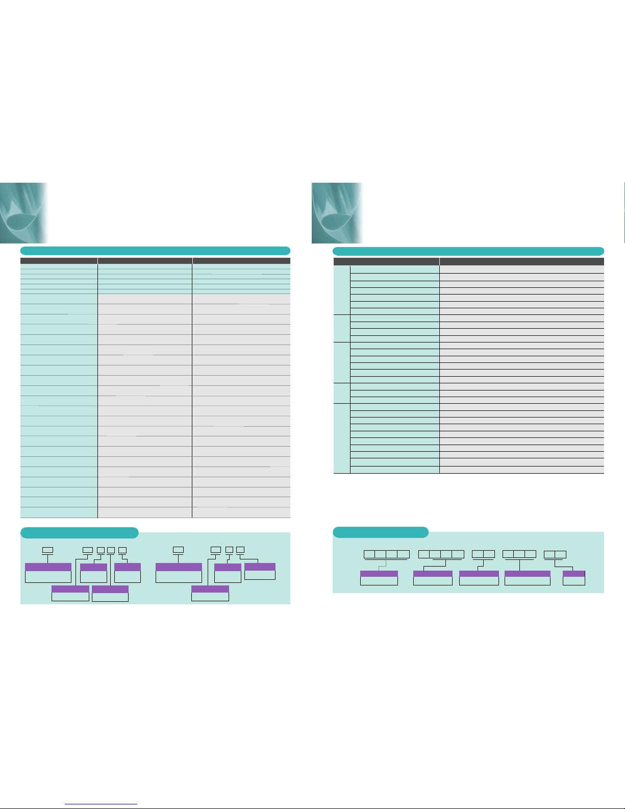
Ratings Specifications
Start Current (% FLC) 300% 350% 400% 450%
Start Duration (seconds) 10 15 20 30
Starts Per Hour 10 10 10 10
Duty Cycle AC53a 70 70 70 70
Off Time (seconds) AC53b 350 345 340 330
Ambient Temperature 45oC45
oC45
oC45
oC
TMS7-4007 AC53a 17 15 14 12
(bypassed) AC53b 18 18 16 14
TMS7-4015 AC53a 33 29 26 22
(bypassed) AC53b 34 34 34 28
TMS7-4018 AC53a 38 34 30 26
(bypassed) AC53b 41 41 41 34
TMS7-4022 AC53a 44 39 35 30
(bypassed) AC53b 47 47 47 39
TMS7-4030 AC53a 67 58 51 45
(bypassed) AC53b 67 62 54 47
TMS7-4037 AC53a 87 75 66 58
(bypassed) AC53b 88 82 71 61
TMS7-4045 AC53a 94 81 71 62
(bypassed) AC53b 96 90 78 66
TMS7-4055 AC53a 123 106 93 81
(bypassed) AC53b 125 120 103 88
TMS7-4075 AC53a 137 119 105 92
(bypassed) AC53b 141 127 111 96
TMS7-4090 AC53a 198 171 151 132
(bypassed) AC53b 202 187 162 140
TMS7-4110 AC53a 236 204 179 156
(bypassed) AC53b 238 224 194 166
TMS7-4132 AC53a 244 211 186 164
(bypassed) AC53b 254 228 198 172
TMS7-4150 AC53a 302 267 233 201
(bypassed) AC53b 302 285 245 209
TMS7-4185 AC53a 405 361 313 267
(bypassed) AC53b 405 395 336 282
TMS7-4220 AC53a 513 456 393 331
(bypassed) AC53b 513 513 435 356
TMS7-4250 AC53a 585 524 450 376
(bypassed) AC53b 585 585 504 410
TMS7-4315 AC53a 628 568 489 412
(bypassed) AC53b 628 626 528 436
TMS7-4400 AC53a 775 710 606 502
(bypassed) AC53b 775 775 672 542
TMS7-4500 AC53a 897 831 706 578
(bypassed) AC53b 897 897 798 632
TMS7-4600 AC53a 1134 989 872 759
(bypassed) AC53b 1153 1153 1006 850
TMS7-4700 AC53a 1385 1210 1066 921
(bypassed) AC53b 1403 1403 1275 1060
TMS7-4800 AC53a 1563 1366 1202 1030
(bypassed) AC53b 1574 1574 1474 1207
Item 3 Wire Rating
300% 350% 400% 450%
10 15 20 30
10 10 10 10
70 70 70 70
350 345 340 330
45oC45
oC45
oC45
oC
26 23 21 18
27 27 24 20
50 44 39 33
51 51 51 42
57 51 45 39
62 62 62 52
66 59 53 45
71 71 71 59
101 87 77 68
101 94 82 71
131 113 99 87
132 122 106 91
141 122 107 93
144 136 117 99
185 159 140 122
188 181 155 132
206 179 158 138
212 190 166 145
297 257 227 198
303 281 243 210
354 306 269 234
357 336 290 250
366 317 279 246
381 342 297 259
453 401 350 302
453 427 368 314
608 542 470 401
608 592 504 424
770 684 590 497
770 770 653 534
878 786 675 564
878 878 756 614
942 852 734 618
942 939 793 654
1163 1065 909 753
1163 1163 1009 813
1346 1247 1059 867
1346 1346 1197 948
1701 1484 1308 1139
1730 1730 1509 1276
2078 1815 1599 1382
2105 2105 1912 1591
2345 2049 1803 1545
2361 2631 2212 1811
6 Wire Rating
Starts Per Hour
e.g. 15 seconds
Start Current
( multiple of FLC )
e.g. 3.5 x 78A (273A)
Starter Current Rating
( Amps )
Under the conditions specified
by the remainder of the AC53
code.
78 A 3.5 -15 :50 -10
AC-53a
On Load Duty Cycle (%)
e.g. 50%
e.g. 345 seconds
Off Time
( seconds )
90 A 3.5 -15 : 345
AC-53b
AC53a AC53b (Bypassed Connection)
1This product has been designed for class A equipment. Use of the product in domestic environments may cause radio interference, in which
case the user may be required to employ additional mitigation methods.
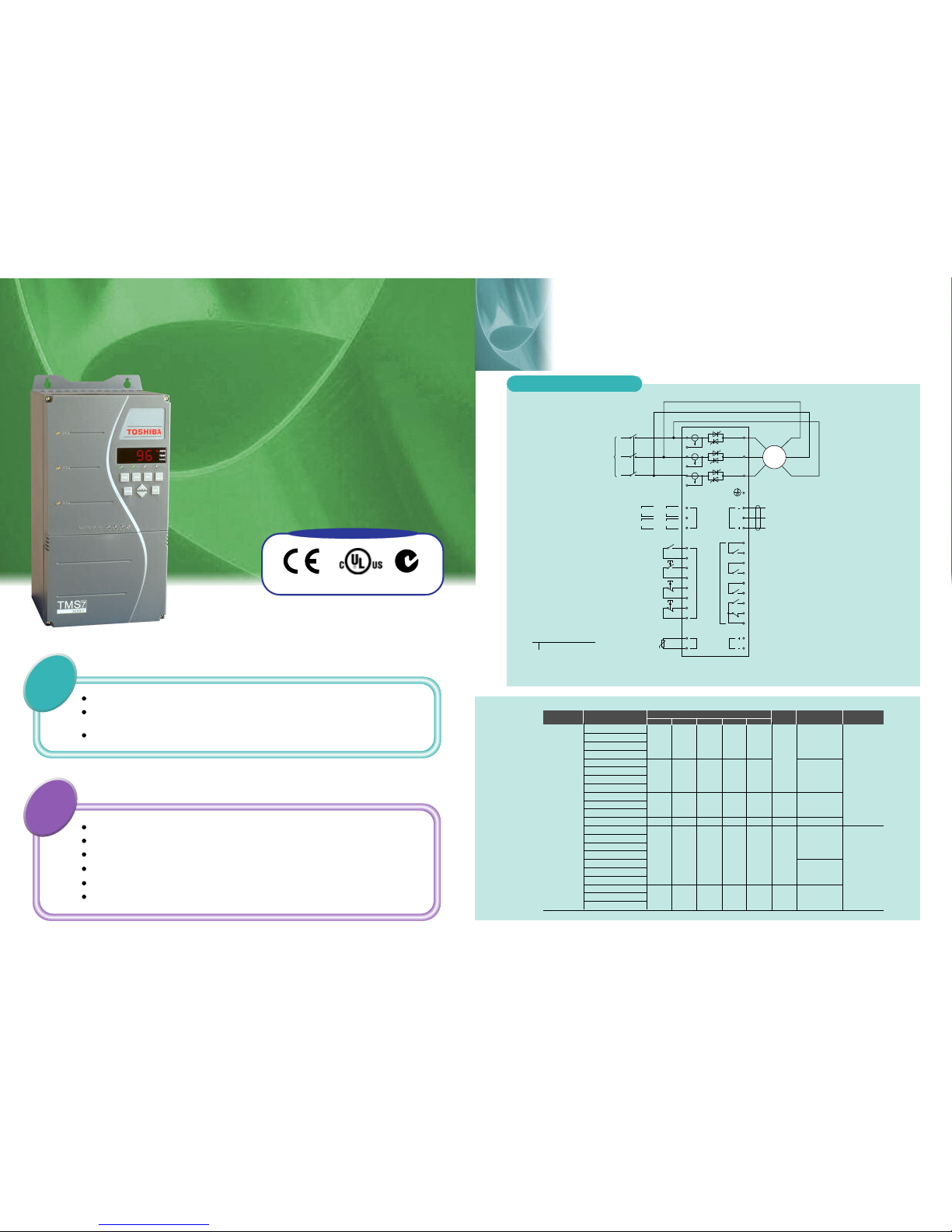
Supply voltage (V5 models) 3 x 200~525VAC (3 Wire Connection), 3 x 200~440VAC (6 Wire Connection)
Supply voltage (V7 models) 3 x 200~ 690VAC (3 Wire Connection), 3 x 200~440VAC (6 Wire Connection)
Electronics Supply (C24 models) 230VAC (+10%/-15%) or 400VAC (+10%/-15%)
Electronics Supply (C45 models) 460VAC (+10%/-15%) or 575VAC (+10%/-15%)
Supply frequency (at start) 50Hz (± 2Hz) or 60Hz (±2Hz)
Supply frequency (during start) > 45Hz (50Hz supply) or > 55Hz (60Hz supply)
Supply frequency (during run) >48Hz (50Hz supply) or > 58Hz (60Hz supply)
Start (I34,I33) Normally Open, Active 24VDC, 8mA approx.
Stop (I22,I21) Normally Closed, Active 24VDC, 8mA approx.
Reset (I12,I11) Normally Closed, Active 24VDC, 8mA approx.
FLC Select (I44,I43) Normally Open, Active 24VDC, 8mA approx.
Run Output (R34,R33) Normally Open, 5A @ 250VAC/360VA, 5A @ 30VDC resistive
Prog. Output A (R44,R43) Normally Open, 5A @ 250VAC/360VA, 5A @ 30VDC resistive
Prog. Output B (R24,R23) Normally Open, 5A @ 250VAC/360VA, 5A @ 30VDC resistive
Prog Output C (R14,R12,R11) Changeover, 5A @ 250VAC/360VA, 5A @ 30VDC resistive
Analogue Output (C6,C7) 4-20mA
Serial Link (C3, C4, C5) RS485 ( Non Isolated )
Enclosure Rating TMS7-4007~4132- IP42 (NEMA 1), TMS7-4150~4800 - IP00 (Open Chassis)
Operating Temperatures -5oC / +60oC
Relative Humidity 5 95% (max non condensing)
Rated short-circuit current 100kA (with semi-conductor fuses)
Rated insulation voltage 690 V
Surges 2kV line to earth, 1kV line to line
Fast transients 2.0kV / 5.0 kHz
Rated impulse withstand voltage 2 kV
Form designation Form 1
Electrostatic discharge 4kV contact discharge, 8 kV air discharge
Equipment class (EMC) Class A1
Radio-frequency electromagnetic field 0.15 MHz - 80 MHz: 140dBµV, 80 MHz - 1 GHz: 10 V/m
Pollution degree Pollution Degree 3
Item Specification
Supply
Control Inputs
Outputs
Environ-
ments
Sundry
----
Contents of the product code
Supply Voltage
V5 = 200 VAC~525 VAC
V7 = 200 VAC~690 VAC
Control Supply Voltage
C24 = 230 VAC & 400 VAC
C45 = 460 VAC & 575 VAC E0 = IP00
E4 = IP42
Enclosure
Nominal kW Rating @ 400V
(@AC53a 3-10:70-10)
eg. 022 = 22kW
TMS 7
Model Name
TMS7 Series
402 2 V5 C24 E4
e.g. 10 Starts
Starter Current Rating
( Amps )
Under the conditions specified
by the remainder of the AC53
code.
Start Current
( multiple of FLC )
e.g. 3.5 x 90A (315A)
e.g. 15 seconds
Start Time
( seconds )
Start Time
( seconds )
Models and Ratings
34