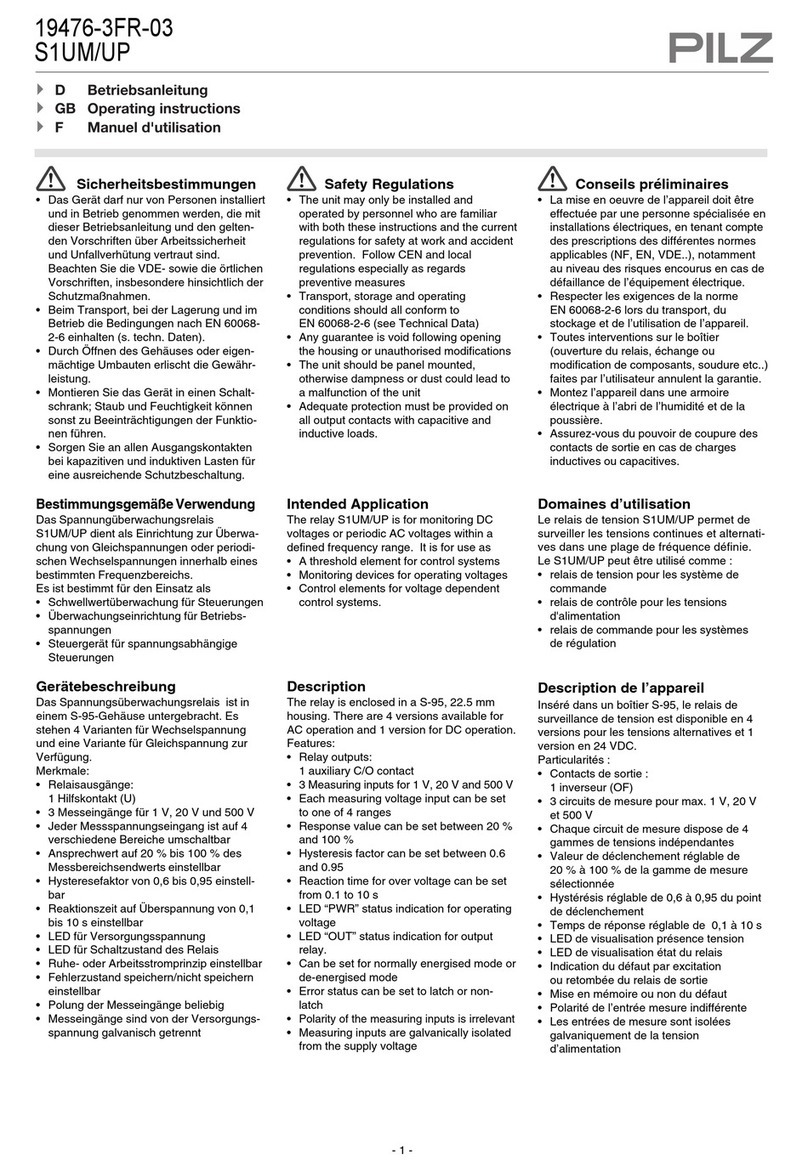
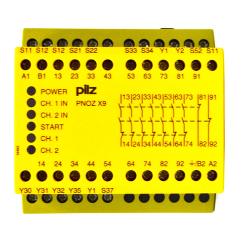
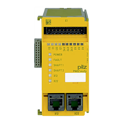
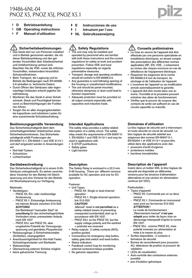
Pilz PNOZ c1 User manual

22197-JA-02
PNOZ c1
- 1 -
J 取扱説明書
22197-JA-02PNOZ c1
Sicherheitsschaltgerät PNOZ c1
582400011
Das Sicherheitsschaltgerät dient dem
sicherheitsgerichteten Unterbrechen eines
Sicherheitsstromkreises.
114368651
Das Sicherheitsschaltgerät erfüllt Forderungen
der EN 60947-5-1, EN 60204-1 und VDE 0113-
1 und darf eingesetzt werden in Anwendungen
mit
`Not-Halt-Tastern
`Schutztüren
Safety relay PNOZ c1
The safety relay provides a safety-related
interruption of a safety circuit.
The safety relay meets the requirements of EN
60947-5-1, EN 60204-1 and VDE 0113-1 and
may be used in applications with
`E-STOP pushbuttons
`Safety gates
安全リレー PNOZ c1
この安全リレーは、安全回路を安全に遮断します。
この製品は、EN 60947-5-1、EN 60204-1、および
VDE 0113-1 の要件を満たしており、以下のアプリ
ケーションで使用できます。
`非常停止ボタン
`安全扉
Zu Ihrer Sicherheit
547263243
`Installieren und nehmen Sie das Gerät nur
dann in Betrieb, wenn Sie diese
Betriebsanleitung gelesen und verstanden
haben und Sie mit den geltenden
Vorschriften über Arbeitssicherheit und
Unfallverhütung vertraut sind.
Beachten Sie die VDE- sowie die örtlichen
Vorschriften, insbesondere hinsichtlich
Schutzmaßnahmen
`Durch Öffnen des Gehäuses oder
eigenmächtige Umbauten erlischt jegliche
Gewährleistung.
1378129931
`Hinweis für Überspannungskategorie III:
Wenn am Gerät höhere Spannungen als
Kleinspannung (>50 V AC oder >120 V DC)
anliegen, müssen angeschlossene
Bedienelemente und Sensoren eine
Bemessungsisolationsspannung von mind.
250 V aufweisen.
For your safety
`Only install and commission the unit if you
have read and understood these operating
instructions and are familiar with the
applicable regulations for health and safety
at work and accident prevention.
Ensure VDE and local regulations are met,
especially those relating to safety.
`Any guarantee is rendered invalid if the
housing is opened or unauthorised
modifications are carried out.
`Note for overvoltage category III: If voltages
higher than low voltage (>50 VAC or >120
VDC) are present on the unit, connected
control elements and sensors must have a
rated insulation voltage of at least 250 V.
安全なご使用のために
`ユニットの取り付けと試運転は、ここにあげる指示
事項ならびに関連する労働安全 衛生および事故防
止の規制を熟知した担当者のみが行ってください。
ご使用にあたり、本製品が VDE やお客様がご使用
される地域の ( 特に安全関連の ) 法規に適合してい
ることを確認してください。
`製品の分解、改造は絶対にしないでください。お守
りいただけない場合、安全、製品の保証を致しかね
ます。
`過電圧カテゴリIIIに関する注意事項:低電圧を超える
電圧 (>50 VAC または >120 VDC) がユニットにかか
る場合、接続する制御ファンクションおよびセンサ
定格絶縁電圧は 250 V 以上でなければなりません。
Gerätemerkmale
1378132107
`Relaisausgänge zwangsgeführt:
3 Sicherheitskontakte (S) unverzögert
1 Hilfskontakt (Ö) unverzögert
`Anschlussmöglichkeiten für:
Not-Halt-Taster
Schutztürgrenztaster
Starttaster
PSENmech, PSENmag
`LED-Anzeige für:
Versorgungsspannung
Schaltzustand Kanal 1
Schaltzustand Kanal 2
Unit features
`Positive-guided relay outputs:
3 safety contacts (N/O), instantaneous
1 auxiliary contact (N/C), instantaneous
`Connection options for:
Emergency stop pushbuttons
Safety gate limit switches
Reset buttons
PSENmech, PSENmag
`LED for:
Supply voltage
Switch status channel 1
Switch status channel 2
製品の特長
`強制ガイドリレー出力 :
安全接点 (N/O)、瞬時 3点
補助接点 (N/C)、瞬時 1点
`以下の接続オプション :
非常停止押しボタン
安全扉リミットスイッチ
リセットボタン
PSENmech、PSENmag
`以下の LED 表示 :
供給電圧
スイッチステータスチャンネル 1
スイッチステータスチャンネル 2
Sicherheitseigenschaften
117575307
Das Schaltgerät erfüllt folgende
Sicherheitsanforderungen:
`Die Schaltung ist redundant mit
Selbstüberwachung aufgebaut.
`Die Sicherheitseinrichtung bleibt auch bei
Ausfall eines Bauteils wirksam.
`Bei jedem Ein-Aus-Zyklus der Maschine wird
automatisch überprüft, ob die Relais der
Sicherheitseinrichtung richtig öffnen und
schließen.
Safety features
The relay meets the following safety
requirements:
`The circuit is redundant with built-in self-
monitoring.
`The safety function remains effective in the
case of a component failure.
`The correct opening and closing of the safety
function relays is tested automatically in
each on-off cycle.
安全上の特徴
製品は以下の安全要件を満たしています :
`自己監視機能が内蔵された冗長回路
`構成部品が故障した場合でも安全機能を維持
`安全機能リレーが正常に開閉しているかどうかを
各オン/オフサイクルで自動的にテスト

- 2 -
Blockschaltbild/Klemmenbelegung Block diagram/terminal configuration ブロック図/端子配列
1382000395
*Isolation zum nicht markierten Bereich: sichere
Trennung (Überspannungskategorie III),
Isolation der Relaiskontakte zueinander:
Basisisolierung (Überspannungskategorie III),
sichere Trennung (Überspannungskategorie II)
*Insulation to the non-marked area: Safe
separation (overvoltage category III),
Insulation of relay contacts against each other:
Basic insulation (overvoltage category III), safe
separation (overvoltage category II)
*マークの付いていない領域に対する絶縁 :安全分離
(過電圧カテゴリ III)、
リレー接点の相互絶縁:基本絶縁 ( 過電圧カテゴリIII)、
安全分離 ( 過電圧カテゴリ II)
Funktionsbeschreibung
1378153099
`Zweikanaliger Betrieb mit
Querschlusserkennung: redundanter
Eingangskreis, erkennt
Erdschlüsse im Start- und Eingangskreis,
Querschlüsse im Eingangskreis.
1387389707
`Automatischer Start: Gerät wird aktiv,
nachdem Eingangskreis geschlossen wurde.
`Manueller Start: Gerät wird aktiv, wenn der
Eingangskreis geschlossen ist und danach
der Startkreis geschlossen wird.
117577867
`Kontaktvervielfältigung und –verstärkung der
unverzögerten Sicherheitskontakte durch
Anschluss von Kontakterweiterungsblöcken
oder externen Schützen möglich.
Function description
`Dual-channel operation with detection of
shorts across contacts: redundant input
circuit, detects
earth faults in the reset and input circuit,
shorts between contacts in the input
circuit.
`Automatic start: Unit is active once the input
circuit has been closed.
`Manual reset: Unit is active once the input
circuit is closed and then the reset circuit is
closed.
`Increase in the number of available
instantaneous safety contacts by connecting
contact expansion modules or external
contactors.
機能の概要
`2チャンネル運転 (短絡検出あり) :冗長入力回路、以
下の検出
リセット回路および入力回路の地絡、
入力回路の短絡
`自動スタート :入力回路が閉じれば、ユニットは起
動します。
`手動リセット :入力回路が閉じた後にリセット回路
が閉じれば、ユニットは起動します。
`接点増設モジュールや外部のコンタクタを接続し
て、利用できる瞬時安全接点の数を増設できます。
Montage
117714315
`Montieren Sie das Sicherheitsschaltgerät in
einen Schaltschrank mit einer Schutzart von
mindestens IP54.
`Befestigen Sie das Gerät mit Hilfe des
Rastelements auf der Rückseite auf einer
Normschiene.
`Sichern Sie das Gerät auf einer senkrechten
Normschiene (35 mm) durch ein
Halteelement (z. B. Endhalter oder
Endwinkel).
Installation
`The safety relay should be installed in a
control cabinet with a protection type of at
least IP54.
`Use the notch on the rear of the unit to attach
it to a DIN rail.
`Ensure the unit is mounted securely on a
vertical DIN rail (35 mm) by using a fixing
element (e.g. retaining bracket or an end
angle).
取り付け
`安全リレーは、保護構造が IP54 以上の制御盤に取
り付ける必要があります。
`ユニットの背面にある刻み目を使用して、DIN レー
ルに取り付けます。
`固定具 ( 固定ブラケットやエンドアングルなど ) を
使用してユニットが垂直 DIN レール (35 mm) に確
実に取り付けられていることを確認してください。
InputInput
A1 A2 S21 S22
=
Power
Reset/
Start
S34
S11 S12
=
K1
K2
13 23 33
24 34
14
41
42
*
S33

- 3 -
Verdrahtung
117588491
Beachten Sie:
`Angaben im Abschnitt „Technische Daten“
unbedingt einhalten.
`Die Ausgänge 13 - 14, 23 - 24, 33 - 34 sind
Sicherheitskontakte, der Ausgang 41 - 42 ist
ein Hilfskontakt (z. B. für Anzeige).
`Vor die Ausgangskontakte eine Sicherung
(s. techn. Daten) schalten, um das
Verschweißen der Kontakte zu verhindern.
`Berechnung der max. Leitungslänge Imax im
Eingangskreis:
Rlmax = max. Gesamtleitungswiderstand
(s. techn. Daten)
Rl/ km = Leitungswiderstand/km
`Leitungsmaterial aus Kupferdraht mit einer
Temperaturbeständigkeit von 60/75 °C
verwenden.
`Sorgen Sie an allen Ausgangskontakten bei
kapazitiven und induktiven Lasten für eine
ausreichende Schutzbeschaltung.
1232919051
`Sorgen Sie beim Anschluss von magnetisch
wirkenden, auf Reedkontakten basierenden
Näherungsschaltern dafür, dass der max.
Einschaltspitzenstrom (am Eingangskreis)
den Näherungsschalter nicht überlastet.
1378293899
`Das Netzteil muss den Vorschriften für
Funktionskleinspannungen mit sicherer
elektrischer Trennung (SELV, PELV) nach
VDE 0100, Teil 410 entsprechen.
1378295691
Wichtig für Querschlusserkennung:
Da diese Funktion nicht einfehlersicher ist, wird
sie von Pilz während der Endkontrolle geprüft.
Wenn Gefahr besteht, dass Sie die
Leitungslängen überschreiten, empfehlen wir
folgende Prüfung nach der Installation des
Geräts:
1. Gerät betriebsbereit (Ausgangskontakte
geschlossen)
2. Die Testklemmen S12, S22 zur
Querschlussprüfung kurzschließen.
3. Die Sicherung im Gerät muss auslösen und
die Ausgangskontakte öffnen.
Leitungslängen in der Größenordnung der
Maximallänge können das Auslösen der
Sicherung um bis zu 2 Minuten verzögern.
4. Sicherung wieder zurücksetzen: den
Kurzschluss entfernen und die
Versorgungsspannung für ca. 1 Minute
abschalten.
Wiring
Please note:
`Information given in the “Technical details”
must be followed.
`Outputs 13 - 14, 23 - 24, 33 - 34 are safety
contacts, output 41 - 42 is an auxiliary
contact (e.g. for display).
`To prevent contact welding, a fuse should be
connected before the output contacts (see
technical details).
`Calculation of the max. cable runs lmax in the
input circuit:
Rlmax = max. overall cable resistance (see
technical details)
Rl/km = cable resistance/km
`Use copper wire that can withstand 60/75 °C.
`Sufficient fuse protection must be provided
on all output contacts with capacitive and
inductive loads.
`When connecting magnetically operated,
reed proximity switches, ensure that the
max. peak inrush current (on the input circuit)
does not overload the proximity switch.
`The power supply must comply with the
regulations for extra low voltages with safe
electrical separation (SELV, PELV) in
accordance with VDE 0100, Part 410.
Important for detection of shorts across
contacts:
As this function for detecting shorts across
contacts is not failsafe, it is tested by Pilz during
the final control check. If there is a danger of
exceeding the cable runs, we recommend the
following test after the installation of the device:
1. Unit ready for operation (output contacts
closed)
2. Short circuit the test terminals S12, S22 for
detecting shorts across the inputs.
3. The unit's fuse must be triggered and the
output contacts must open. Cable lengths in
the scale of the maximum length can delay
the fuse triggering for up to 2 minutes.
4. Reset the fuse: remove the short circuit and
switch off the supply voltage for approx. 1
minute.
配線
注意事項 :
`「技術データ」に記載されている情報に従ってくだ
さい。
`出力 13 ~14、23 ~24、33 ~34 は安全接点、出力
41 ~42 は補助接点 ( ディスプレイ用など ) です。
`接点の溶着を防ぐために、出力接点の前に必ず
ヒューズを接続してください (「技術データ」を参照 )。
`入力回路の最大ケーブル長 lmax は、以下の計算式で
求められます :
Rlmax = ケーブル全体の最大抵抗値
(「技術データ」を参照 )
Rl/km = ケーブル抵抗値 /km
`60/75 ℃の耐熱性を持つ銅線を使用してください。
`容量性、誘導負荷のある接点を保護するため、出力
回路にはヒューズを取り付けてください。
`磁気動作式のリード近接スイッチを接続する場合
は、入力回路の最大ピーク突入電流が近接スイッチ
の許容電流を超えないことを確認してください。
`電源は、VDE 0100, Part 410 に準拠した安全分離
に関する低電圧指令 (SELV、PELV) に適合する必
要があります。
短絡検出に関する重要事項 :
短絡を検出するためのこの機能はフェイルセーフで
ないため、最終制御チェック時にピルツによってテス
トされています。ケーブル長が許容値を超えている可
能性がある場合は、装置の設置後に次のテストを実施
することをお勧めします。
1. ユニットを動作可能な状態にします (出力接点閉)。
2. テスト端子 S12、S22 を短絡し、入力間の短絡を
検出します。
3. ユニットのヒューズが作動して、出力接点が開く必
要があります。ケーブル長が最大長に近い場合、
ヒューズが作動するまでに最大で2分の遅れが発生
することがあります。
4. ヒューズをリセットします。短絡を取り除き、電源を
約1分間オフにします。
Betriebsbereitschaft herstellen Preparing for operation 運転の準備
Anschluss Connection 接続
`Versorgungsspannung `Supply voltage `供給電圧
Versorgungsspannung/power supply/ 電源 AC DC
`Eingangskreis `Input circuit `入力回路
Eingangskreis/input circuit/ 入力回路 Einkanalig/single-channel/1チャンネル Zweikanalig/dual-channel/2チャンネル
Not-Halt
mit Querschlusserkennung/
E-STOP
with detection of shorts across contacts/
非常停止
短絡検出あり
Schutztür
mit Querschlusserkennung/
safety gate
with detection of shorts across contacts/
安全扉
短絡検出あり
Rlmax
Rl / km
Imax =
Rlmax
Rl / km
Imax =
Rlmax
Rl / km
Imax =
A1 L+
A2 L-
S1
S22
S21
S12
S11
S1 S2
S12
S11
S22
S21

- 4 -
`Startkreis/Rückführkreis `Reset circuit/ `リセット回路/
Startkreis/Rückführkreis/
reset circuit/feedback loop
リセット回路/フィードバック
Startkreis/reset circuit/ リセット回路 Rückführkreis/feedback loop/ フィードバック
automatischer Start/
automatic reset/
自動リセット
manueller Start/
manual/monitored reset
手動/モニタリングリセット
1391458059
WICHTIG
Das Gerät startet bei überbrücktem
Startkreis automatisch. Verhindern Sie
einen unerwarteten Wiederanlauf durch
externe Schaltungsmaßnahmen.
NOTICE
The device starts automatically when reset
circuit is overridden. Use external circuit
measures to prevent an unexpected
restart.
重要
リセット回路が無効になると、装置が自動的に起
動します。予期せぬ再起動を防止するには、外部
回路による措置を講じてください。
Betrieb
1378745611
Das Gerät ist betriebsbereit, wenn die LED
Power permanent leuchtet.
LEDs zeigen den Status und Fehler während
des Betriebs an:
Operation
The unit is ready for operation when the Power
LED is permanently lit.
LEDs indicate the status and errors during
operation:
運転
電源 LED が点灯状態の場合、ユニットを運転するこ
とができます。
LED は運転中にステータスやエラーを表示します。
Statusanzeigen Status indicators ステータス表示
551604875
Power
Versorgungsspannung liegt an. Power
Supply voltage is present.
Power
電源が供給されています。
1382017419
CH.1
Sicherheitskontakte von Kanal K1 sind
geschlossen.
CH.1
Safety contacts of channel K1 are closed.
CH.1
チャンネル K1 の安全接点が閉じています。
1382041227
CH.2
Sicherheitskontakte von Kanal K2 sind
geschlossen.
CH.2
Safety contacts of channel K2 are closed.
CH.2
チャンネル K2 の安全接点が閉じています。
Fehleranzeigen Error indicators エラー表示
551771659
Alle LEDs aus
Diagnose: Querschluss/Erdschluss; Gerät
ausgeschaltet
`Abhilfe: Querschluss/Erdschluss
beheben, Versorgungsspannung für 1
Min. ausschalten.
All LEDs off
Diagnostics: Short across contacts/earth
fault; unit switched off
`Remedy: Rectify short across contacts/
earth fault, switch off supply voltage for 1
min.
全LED 消灯
診断 :短絡/地絡 : ユニットの電源オフ
`処置 : 短絡/地絡を修復し、電源を 1分間オフ
にします。
1387696267
LED Power aus
Diagnose: Kurzschluss oder
Versorgungsspannung fehlt
`Abhilfe: Kurzsschluss beheben oder
Versorgungsspannung anlegen
LED Power off
Diagnostics: Short circuit or supply voltage
failure.
`Remedy: Rectify short circuit or connect
supply voltage
「Power」LED 消灯
診断 :短絡または供給電圧の異常。
`処置 : 短絡を修復するか、供給電圧を接続し
ます。
Fehler - Störungen
551266315
`Fehlfunktionen der Kontakte: Bei
verschweißten Kontakten ist nach Öffnen
des Eingangskreises keine neue Aktivierung
möglich.
Faults - malfunctions
`Contact malfunctions: If the contacts have
welded, reactivation will not be possible after
the input circuit has opened.
エラー - 故障
`接点不良 :接点が溶着している場合、入力回路が開
いた後には再起動できません。
Technische Daten Technical details 技術データ
Elektrische Daten Electrical data 電気的データ
Versorgungsspannung Supply voltage 供給電圧
Versorgungsspannung UBDC Supply voltage UBDC 供給電圧 UBDC 24 V
Spannungstoleranz Voltage tolerance 許容電圧 ( 供給電圧に対して )-15 %/+10 %
Leistungsaufnahme bei UBDC Power consumption at UBDC 消費電力 (UBDC 時)2.5 W
Restwelligkeit DC Residual ripple DC 残留リップル (DC) 160 %
Spannung und Strom an Voltage and current at 電圧/電流
Eingangskreis DC: 24,0 V Input circuit DC: 24,0 V 入力回路 (DC): 24.0 V 30.0 mA
Startkreis DC: 24,0 V Reset circuit DC: 24,0 V リセット回路 (DC): 24.0 V 40.0 mA
Rückführkreis DC: 24,0 V Feedback loop DC: 24,0 V フィードバック (DC): 24.0 V 40.0 mA
Anzahl der Ausgangskontakte Number of output contacts 出力接点数
Sicherheitskontakte (S)
unverzögert:
Safety contacts (S) instantaneous: 瞬時安全接点 (S): 3
Hilfskontakte (Ö): Auxiliary contacts (N/C): 補助接点 (N/C): 1
S33
S34
K5 K6
K5
L1
N
K6
S33
13 (23,33
S34
14 (24,34
S33
S34
S3
K5 K6
K5 L1
K6
S33
S34
S3
N
13 (23, 33
14 (24 ,34

- 5 -
Gebrauchskategorie nach EN
60947-4-1
Utilisation category in accordance
with EN 60947-4-1
EN 60947-4-1 に適合する使用カテゴリ
Sicherheitskontakte: AC1 bei 240 V Safety contacts: AC1 at 240 V 安全接点 : AC1、240 V Imin:0.01 A 、Imax:6.0 A
Pmax:1500 VA
Sicherheitskontakte: DC1 bei 24 V Safety contacts: DC1 at 24 V 安全接点 : DC1、24 V Imin:0.01 A 、Imax:6.0 A
Pmax:150 W
Hilfskontakte: AC1 bei 240 V Auxiliary contacts: AC1 at 240 V 補助接点 : AC1、240 V Imin:0.01 A 、Imax:6.0 A
Pmax:1500 VA
Hilfskontakte: DC1 bei 24 V Auxiliary contacts: DC1 at 24 V 補助接点 : DC1、24 V Imin:0.01 A 、Imax:6.0 A
Pmax:150 W
Gebrauchskategorie nach EN
60947-5-1
Utilisation category in accordance
with EN 60947-5-1
EN 60947-5-1 に適合する使用カテゴリ
Sicherheitskontakte: AC15 bei 230
V
Safety contacts: AC15 at 230 V 安全接点 : AC15、230 V Imax:5.0 A
Sicherheitskontakte: DC13 bei 24 V
(6 Schaltspiele/min)
Safety contacts: DC13 at 24 V (6
cycles/min)
安全接点 : DC13、24 V (6 サイクル/分 )Imax:5.0 A
Hilfskontakte: AC15 bei 230 V Auxiliary contacts: AC15 at 230 V 補助接点 : AC15、230 V Imax:5.0 A
Hilfskontakte: DC13 bei 24 V (6
Schaltspiele/min)
Auxiliary contacts: DC13 at 24 V (6
cycles/min)
補助接点 : DC13、24 V (6 サイクル/分 )Imax:5.0 A
Kontaktmaterial Contact material 接点材料 AgCuNi + 0.2 μm Au
Kontaktabsicherung, extern (IK= 1
kA) nach EN 60947-5-1
External contact fuse protection (IK
= 1 kA) to EN 60947-5-1
接点保護用外部ヒューズ (IK= 1 kA)、
EN 60947-5-1 適合
Schmelzsicherung flinkBlow-outfuse,quick クイックブロータイプ
Schmelzsicherung träge Blow-out fuse, slow スローブロータイプ
Sicherheitskontakte: Safety contacts: 安全接点 : 6 A
Hilfskontakte: Auxiliary contacts: 補助接点 : 6 A
Sicherungsautomat 24V AC/DC,
Charakteristik B/C
Circuit breaker 24 VAC/DC,
characteristic B/C
サーキットブレーカ 24 VAC/DC、
B/C タイプ
Sicherheitskontakte: Safety contacts: 安全接点 : 6 A
Hilfskontakte: Auxiliary contacts: 補助接点 : 6 A
Max. Gesamtleitungswiderstand
Rlmax
Eingangskreise, Startkreise
Max. overall cable resistance Rlmax
input circuits, reset circuits
ケーブル全体の最大抵抗 Rlmax
入力回路、リセット回路
zweikanalig mit
Querschlusserkennung bei UBDC
dual-channel with detect. of shorts
across contacts at UBDC
2チャンネル、短絡検出あり (UBDC 時)15 Ω
Min. Eingangswiderstand im
Einschaltmoment
Min. input resistance when
switching on
最小入力抵抗 ( スイッチオン時 )88 Ω
Sicherheitstechnische
Kenndaten
Safety-related characteristic
data
安全関連特性データ
PL nach EN ISO 13849-1: 2006 PL in accordance with EN ISO
13849-1: 2006
PL (EN ISO 13849-1: 2006 適合 )
PL e ( カテゴリ 4)
Kategorie nach EN 954-1 Category in accordance with EN
954-1
カテゴリ (EN 954-1 適合 )
カテゴリ 4
SIL CL nach EN IEC 62061 SIL CL in accordance with EN IEC
62061
SIL CL (EN IEC 62061 適合 )
SIL CL 3
PFH nach EN IEC 62061 PFH in accordance with EN IEC
62061
PFH (EN IEC 62061 適合 )
2.31E-09
SIL nach IEC 61511 SIL in accordance with IEC 61511 SIL (IEC 61511 適合 )
SIL 3
PFD nach IEC 61511 PFD in accordance with IEC 61511 PFD (IEC 61511 適合 )
2.03E-06
TM[Jahr] nach EN ISO 13849-1:
2006
TM[year] in accordance with EN
ISO 13849-1: 2006
TM[ 年] (EN ISO 13849-1: 2006 適合 )20
Zeiten Times 時間
Einschaltverzögerung Switch-on delay スイッチオンディレイ
bei automatischem Start typ. with automatic reset typ. 自動リセット ( 標準値 )250 ms
bei automatischem Start max. with automatic reset max. 自動リセット ( 最大値 )450 ms
bei automatischem Start nach
Netz-Ein typ.
with automatic reset after power on
typ.
電源 ON 後の自動リセット ( 標準値 )250 ms
bei automatischem Start nach
Netz-Ein max.
with automatic reset after power on
max.
電源 ON 後の自動リセット ( 最大値 )450 ms
bei manuellem Start typ. with manual reset typ. 手動リセット ( 標準値 )125 ms
bei manuellem Start max. with manual reset max. 手動リセット ( 最大値 )450 ms
Rückfallverzögerung Delay-on de-energisation 応答時間
bei Not-Halt typ. with E-STOP typ. 非常停止 ( 標準値 )15 ms
bei Not-Halt max. with E-STOP max. 非常停止 ( 最大値 )30 ms
bei Netzausfall typ. with power failure typ. 停電 ( 標準値 )60 ms
bei Netzausfall max. with power failure max. 停電 ( 最大値 )100 ms
Elektrische Daten Electrical data 電気的データ

- 6 -
Wiederbereitschaftszeit bei max.
Schaltfrequenz 1/s
Recovery time at max. switching
frequency 1/s
回復時間
(スイッチング周波数最大 1/s の場合 )
nach Not-Halt after E-STOP 非常停止後 300 ms
nach Netzausfall after power failure 停電後 300 ms
Gleichzeitigkeit Kanal 1 und 2 Simultaneity, channel 1 and 2 同期、チャンネル 1と2∞
Überbrückung bei
Spannungseinbrüchen der
Versorgungsspannung
Supply interruption before de-
energisation
電源瞬断許容時間 20 ms
Umweltdaten Environmental data 環境データ
EMV EMC EMC EN 60947-5-1、EN 61000-6-2、
EN 61000-6-4
Schwingungen nach EN 60068-2-6 Vibration to EN 60068-2-6 耐振動 (EN 60068-2-6)
Frequenz Frequency 周波数 10 - 55 Hz
Amplitude Amplitude 振幅 0.35 mm
Klimabeanspruchung Climatic suitability 周囲環境条件 EN 60068-2-78
Luft- und Kriechstrecken nach EN
60947-1
Airgap creepage in accordance
with EN 60947-1
沿面距離 (EN 60947-1)
Verschmutzungsgrad Pollution degree 汚染度 2
Überspannungskategorie Overvoltage category 過電圧カテゴリ III
Bemessungsisolationsspannung Rated insulation voltage 定格絶縁電圧 250 V
Bemessungsstoßspannungsfestigk
eit
Rated impulse withstand voltage 定格インパルス耐電圧 6.00 kV
Umgebungstemperatur Ambient temperature 周囲温度 -10 - 55 ℃
Lagertemperatur Storage temperature 保管温度 -40 - 85 ℃
Schutzart Protection type 保護構造
Einbauraum (z. B. Schaltschrank) Mounting (e.g. cabinet) 取り付け ( 制御盤など )IP54
Gehäuse Housing ハウジング IP40
Klemmenbereich Terminals 端子部 IP20
Mechanische Daten Mechanical data 機械的データ
Gehäusematerial Housing material ケース素材
Gehäuse Housing ハウジング PC
Querschnitt des Außenleiters bei
Schraubklemmen
Cross section of external
conductors with screw terminals
端子接続線径 ( スクリュー式端子台 )
2 Leiter gleichen Querschnitts,
flexibel:
2 core, same cross section, flexible: 2芯( 同一線径 )、撚線
Querschnitt des Außenleiters bei
Federkraftklemmen: flexibel mit/
ohne Aderendhülse
Cross section of external
conductors with spring-loaded
terminals: Flexible with/without
crimp connectors
端子接続線径 ( ケージ式端子台 )
(撚線、クリンプ端子あり/なし )
0.25 ~1.50 mm2、24 ~16 AWG
Federkraftklemmen: Klemmstellen
pro Anschluss
Spring-loaded terminals: Terminal
points per connection
ケージ式端子台 :接続ごとの配線口 1
Abisolierlänge Stripping length 電線剥き線長さ 9 mm
Abmessungen Dimensions 寸法
Höhe Height 高さ 105.0 mm
Breite Width 幅22.5 mm
Tiefe Depth 奥行き 100.0 mm
Gewicht Weight 重量 155 g
Zeiten Times 時間

- 7 -
1176133131
ACHTUNG!
Beachten Sie unbedingt die
Lebensdauerkurven der Relais. Die
sicherheitstechnischen Kennzahlen der
Relaisausgänge gelten nur, solange die
Werte der Lebensdauerkurven eingehalten
werden.
Der PFH-Wert ist abhängig von der
Schaltfrequenz und der Belastung des
Relaisausganges.
Solange die Lebensdauerkurven nicht erreicht
werden, kann der angegebene PFH-Wert
unabhängig von der Schaltfrequenz und der
Belastung verwendet werden, da der PFH-Wert
den B10d-Wert der Relais sowie die
Ausfallraten der anderen Bauteile bereits
berücksichtigt.
1077650443
Alle in einer Sicherheitsfunktion verwendeten
Einheiten müssen bei der Berechnung der
Sicherheitskennwerte berücksichtigt werden.
1312356363
INFO
Die SIL-/PL-Werte einer
Sicherheitsfunktion sind nicht identisch mit
den SIL-/PL-Werten der verwendeten
Geräte und können von diesen abweichen.
Wir empfehlen zur Berechnung der SIL-/
PL-Werte der Sicherheitsfunktion das
Software-Tool PAScal.
585241611
Es gelten die 2011-11 aktuellen Ausgaben der
Normen.
CAUTION!
It is essential to consider the relay's service
life graphs. The relay outputs' safety-
related characteristic data is only valid if the
values in the service life graphs are met.
The PFH value depends on the switching
frequency and the load on the relay output. If
the service life graphs are not accessible, the
stated PFH value can be used irrespective of
the switching frequency and the load, as the
PFH value already considers the relay's B10d
value as well as the failure rates of the other
components.
All the units used within a safety function must
be considered when calculating the safety
characteristic data.
INFORMATION
A safety function's SIL/PL values are not
identical to the SIL/PL values of the units
that are used and may be different. We
recommend that you use the PAScal
software tool to calculate the safety
function's SIL/PL values.
The standards current on 2011-11 apply.
注意 !
リレーの製品寿命グラフを必ず考慮してくださ
い。リレー出力の安全関連特性データは、製品寿
命グラフの値に適合している場合のみ有効です。
PFH 値は、スイッチング頻度とリレー出力の負荷に
応じて決まります。製品寿命グラフを利用できない場
合は、スイッチング頻度と負荷に関係なく指定された
PFH 値を使用できます。これは、リレーの B10d 値
およびその他の部品の故障率が、PFH 値で既に考慮
されているためです。
安全特性データを計算する場合は、安全機能で使用さ
れるすべてのユニットについて考慮する必要があり
ます。
インフォメーション
安全機能の SIL/PL 値は、使用されるユニットの
SIL/PL値と同じではなく、異なる場合があります。
安全機能の SIL/PL 値の計算には、PAScal ソフト
ウェアツールを使用することをお勧めします。
2011 年11 月現在有効な規格を適用。
Konventioneller thermischer Strom bei
gleichzeitiger Belastung mehrerer
Kontakte
Conventional thermal current while
loading several contacts
使用接点数と定格電流
Ith pro Kontakt bei UBDC Ith per contact at UBDC 接点あたりの Ith (UBDC 時)
Anzahl der Kontakte Number of contacts 接点数 Ith
1116.00 A
2226.00 A
3335.00 A
Lebensdauerkurve der Ausgangsrelais
1196936075
Die Lebensdauerkurven geben an, ab welcher
Schaltspielzahl mit verschleißbedingten
Ausfällen gerechnet werden muss. Der
Verschleiß wird vor allem durch die elektrische
Belastung verursacht, der mechanische
Verschleiß ist vernachlässigbar.
Service life graph of output relays
The service life graphs indicate the number of
cycles from which failures due to wear must be
expected. The wear is mainly caused by the
electrical load; the mechanical load is
negligible.
出力リレーの製品寿命グラフ
製品寿命グラフには、摩耗による故障が予想されるサ
イクル数が示されています。摩耗は主に電気的負荷に
よって生じ、機械的負荷は無視できます。

Originalbetriebsanleitung/ オリジナルマニュアル /Notice originale
22197-JA-02, 2012-01 Printed in Germany
22197-JA-022012- 01Printed in Germany
1221417611
Beispiel
`Induktive Last: 0,2 A
`Gebrauchskategorie: AC15
`Lebensdauer der Kontakte: 2 000 000
Schaltspiele
Solange die zu realisierende Applikation eine
Schaltspielzahl von weniger als 2 000 000
Schaltspiele erfordert, kann mit dem PFH-Wert
(s. technische Daten) gerechnet werden.
Um die Lebensdauer zu erhöhen, an allen
Ausgangskontakten für eine ausreichende
Funkenlöschung sorgen. Bei kapazitiven
Lasten sind eventuell auftretende Stromspitzen
zu beachten. Bei DC-Schützen Freilaufdioden
zur Funkenlöschung einsetzen.
Example
`Inductive load: 0,2 A
`Utilisation category: AC15
`Contact service life: 2,000,000 cycles
Provided the application requires fewer than
2,000,000 cycles, the PFH value (see technical
details) can be used in the calculation.
To increase the service life, sufficient spark
suppression must be provided on all output
contacts. With capacitive loads, any power
surges that occur must be noted. With
contactors, use freewheel diodes for spark
suppression.
例
`誘導負荷 : 0.2 A
`使用カテゴリ : AC15
`接点の製品寿命 : 2,000,000 サイクル
アプリケーションで必要なサイクル数が 2,000,000
未満であることを条件に、PFH 値(「技術データ」を
参照 ) を計算で使用できます。
製品の寿命を延ばすには、すべての出力接点に十分な
スパーク抑制を用意する必要があります。容量負荷の
場合、発生する電力サージに注意する必要がありま
す。コンタクタの場合は、スパーク抑制にフリーホ
イールダイオードを使用してください。
Bestelldaten Order reference ご注文のための情報
Typ/
Type/
型式
Merkmale/
Features/
機能
Klemmen/
Terminals/
端子
Bestell-Nr./
Order no./
型番
PNOZ c1 24 V DC mit Federkraftklemmen/ 710 001
EG-Konformitätserklärung
1139424011
Diese(s) Produkt(e) erfüllen die Anforderungen
der Richtlinie 2006/42/EG über Maschinen des
europäischen Parlaments und des Rates. Die
vollständige EG-Konformitätserklärung finden
Sie im Internet unter www.pilz.com.
Bevollmächtigter: Norbert Fröhlich, Pilz GmbH
& Co. KG, Felix-Wankel-Str. 2, 73760
Ostfildern, Deutschland
EC Declaration of Conformity
This (these) product(s) comply with the
requirements of Directive 2006/42/EC of the
European Parliament and of the Council on
machinery. The complete EC Declaration of
Conformity is available on the Internet at
www.pilz.com.
Authorised representative: Norbert Fröhlich,
Pilz GmbH & Co. KG, Felix-Wankel-Str. 2,
73760 Ostfildern, Germany
EC 適合性宣言
本製品は、欧州議会の指令 2006/42/EC および欧州理
事会の機械指令に適合しています。EC 適合性宣言書
一式は、インターネット (www.pilz.com) から入手で
きます。
正式代表者 :Norbert Frhlich、Pilz GmbH & Co. KG,
Felix-Wankel-Str.2, 73760 Ostfildern, Germany
Other manuals for PNOZ c1
1
Table of contents
Other Pilz Relay manuals

Pilz
Pilz PNOZ X3.1 User manual

Pilz
Pilz PNOZ s3 Series User manual

Pilz
Pilz PNOZ s30 User manual

Pilz
Pilz S1MO 22216-3FR-01 User manual

Pilz
Pilz PNOZ X Series User manual

Pilz
Pilz S1M0 User manual

Pilz
Pilz PNOZ X9 User manual

Pilz
Pilz PNOZ XV3.1P User manual

Pilz
Pilz PNOZX4 User manual

Pilz
Pilz PNOZ X Series User manual
Popular Relay manuals by other brands

LinTronic
LinTronic 208 Operation manual

Extron electronics
Extron electronics IPA T RLY4 user guide

Allen-Bradley
Allen-Bradley 193-EF1A Installation instruction

Omnitracs
Omnitracs XRS XR-980 Installation

Rockwell Automation
Rockwell Automation Allen-Bradley Guardmaster Minotaur... installation instructions

ZIEHL
ZIEHL MS220C operating instructions